


We have a new MULTUS B400-W but no one seems to know how to load a downloaded Sandvik Coromant tool into the CAS (Collision Avoidance System)
we have tested converting the file to an .STL format and this did seem to work to a point. we managed to get the tool in as a graphic but have had no luck in positioning it correctly in 3D space.
No matter how we try the tool always appears way below the the M- spindles center line???
All the tools that came ready loaded into the machines tool library sit perfect but we do realy need to be able to load all those weird tools that were not included here.
this one for eg we can not get in C6-DCMNN-00115-12
found as a .stp 3D model for download at
www.coromant.sandvik.com
and then clicking on "find CAD drawings"
and pasting in... C6-DCMNN-00115-12
Help please any one who is a wizz at the CAS system please.
realy need to be able to position the tools correctly in the 3D space environment.
How the... do you do it?
Results 1 to 10 of 10
-
03-23-2010, 11:38 AM #1
 Registered
- Join Date
- Sep 2009
- Posts
- 16
 MULTUS B400-W. Positioning .stp .stl 3D tools into Collision Avoidance System.
-
03-24-2010, 08:47 AM #2
Registered
- Join Date
- Jun 2005
- Posts
- 142
I am no wizz , but would like to help.
I know how frustrated I got when trying to set the models!
It will be difficult for me to give details here as I'm at home and not at our machine.
The sandvik model needs an insert added to it even though it's already shown. It will be yellow with a green outline on its edges when done, and occupy the same space as the sandvik one.
After you measure the tool with the touch setter, you go back to, Define Tools,
Edit Set Tool, Change Settings, Set Offset. You may need to Change Direction as well.
I hope this little bit helps somewhat. I will go through it at work tomorrow with your tool model and take note of each step, then post it back here if you've had no success.
-
03-24-2010, 11:28 AM #3
Registered
- Join Date
- Sep 2009
- Posts
- 16
Wow what a hit.
Thank you so very much. I too am at home but with a broken finger. I go into work as often as i can to work around these problems. The machine is very new to us and i am more used to heidenhains system so this is very different for me.
Our OKUMA is running a job with our robot just now and is due to be finnished with these details around midnight of next Saturday. THEN i can play around i think and get to the bottom of this,
If you could as you say take note of the steps you made this would be fabulouse. and any problems to watch out for.
Also as a point of interest. How did you convert your .stp files to .STL
and is there any limitation on file size as some of ours loaded and others did not.
It seems the higher file size is rejected by the Okuma but where the size boundary is, i dont know.
I realy look forward to classing this post as a Nr1 help post
and even this small amount of guidance is worth gold.
Thank you.
-
03-25-2010, 07:10 AM #4
Registered
- Join Date
- Jun 2008
- Posts
- 372
Save the below file to your PC
Unzip it
Save it to a USB stick
Open CAS and say read file
Choose USB0 or USB1
Basically your STL file needs to have less than 3000 triangles. It must be watertight and error free
-
03-25-2010, 01:12 PM #5
Registered
- Join Date
- Sep 2009
- Posts
- 16
Okay i see this is a .OECTOL file of the type that the machine produces.
I will of course test this file at the nearest possible opportunity.
I would hope it is the desired tool in full working order. BUT BUT BUT
I still kneed the Knowledge of how to do this myself.
It will be interesting to see though if it translates into the correct 3D space and not offset as we have seen before.
I appreciate your help and thank you very much for your participation in this thread.
If you know the step by step instructions on "how to" i would very much like to hear it.
Thank you once again.
-
03-26-2010, 01:17 AM #6
Registered
- Join Date
- Jun 2005
- Posts
- 142
Hello again,
In regards to converting .stp to .stl, at work we have Pro Engineer and I've also used Inventor to do this.
I guess most 3d parametric cad programs should handle it.
But to get some models smaller than 3000 triangles, we found a free download called EasyFIT Professional which has a "triangle reduction" function.
You need to convert to .stl first as this software can't do it.
Unfortunately I'm at home feeling (and being!) quite sick and wont be near a machine for a few days.
I hope someone else can guide you further.
Of course, your Okuma reps should be able to help, lol.
-
03-28-2010, 09:40 AM #7
Registered
- Join Date
- Jun 2008
- Posts
- 372
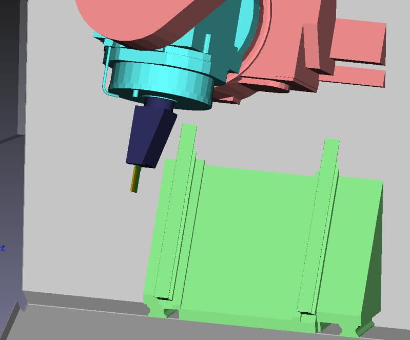
The below pic is from Solidworks, Z axis is the Axis of the Milling spindle Y axis is the Y axis of the machine tool

This will give you the below on the machine
-
03-31-2010, 07:33 AM #8
Registered
- Join Date
- Sep 2009
- Posts
- 16
Bad news for me is the machine is now getting so busy with the old jobs we have lined up for it.
Now i am going to get no time to test all of this, as you are all aware i hope, i am at home with a broken finger and plan to return the beginning of May... long time.
All of this information is so very much appreciated and i really want you to all know this,
I have every intention to summarize all of this at the end with a step by step instruction on "how to"
The last piece of information from budgieW was very interesting and shall also be put into practice. Have often wondered about this. so yeah. good stuff.
Please dont stop with the forthcoming information as i will need it all for my return.
YES the company who installed our new machine SHOULD be able to give us these answers but if they could do this in the time frame i am thinking of, i would not be turning to you guys and cnczone.
I am itching to get back and try this and post more back to this thread.
thanks again.
-
03-31-2010, 09:29 AM #9
Registered
- Join Date
- Jun 2008
- Posts
- 372
A nice STL utility can be downloaded here
http://www.click-to-fit.com/easyfit....ng=en#download
-
04-08-2010, 01:08 PM #10
Registered
- Join Date
- Jun 2005
- Posts
- 142
I've attached a procedure that was given to me by Okuma.
The pics show a Macturn, but the CAS is the same.
It helped me out a lot. It's a shame that our Multus came without this sort of info, as it really makes learning a new machine very frustrating.
Hope it helps you too.

 Reply With Quote
Similar Threads
-
Collision Avoidance System
By zooloader in forum OkumaReplies: 32Last Post: 08-29-2018, 03:51 PM -
help with system and manual tools please
By mls in forum BobCad-CamReplies: 4Last Post: 11-25-2009, 04:28 PM -
collision while surface roughing verify
By manuelc149 in forum MastercamReplies: 3Last Post: 11-08-2008, 02:49 AM -
Collision Detection and Use Solid as Clamp?
By GisMo in forum FeatureCAM CAD/CAMReplies: 0Last Post: 06-26-2008, 02:15 AM
