


Jermie
I like your bench, I got the metal stand they sold with the mill. Yours is much better I will need to make a new one myself to keep up with the jones
We used the same ball screws on our conversion from LMB.
We cut our own ends for the x and y and found them very tough to cut. When we got the z we had them cut them at no charge, there where spot on.
With the 6 nuts your going for the spring loading to reduce your backlash? Do not be scared to put a good amount of force between them, it took us two goes to get it right
We made our own bearing blocks this allowed us to keep maximum x travel
If interested photo attached
The first photo shows the table at full right movement (a little out of focus)
The two gold coloured lines on either side of the bearing are the oil lines for the two nuts.
Next photo shows the servo motor mount and bearing block.
Wish you all the best
Russell
Thread: RF-45 CNC Advice needed
Results 61 to 80 of 569
-
08-14-2010, 04:57 PM #61
 Registered
- Join Date
- Sep 2008
- Posts
- 133
www.vapourforge.com ..................I recycle electrons.
-
08-14-2010, 05:50 PM #62
Registered
- Join Date
- Aug 2009
- Posts
- 899
Russell,
I like how you attached the motors directly to the axis but why not step it down with a belt drive? I do plan on using the double nuts with pressure between them to get rid of all backlash.
I already have all 3 screws so I will have to machine them or have them cut somewhere local but I do not have a lathe large enough to cut them right now. I plan on heating up the ends to soften them up before cutting.
-
08-15-2010, 03:42 AM #63
Registered
- Join Date
- Aug 2009
- Posts
- 899
Well the decision has been made. I will be ordering a G0602 10"X22" Lathe to match the ZX45 and so I can turn the ball screws.
-
08-15-2010, 04:16 AM #64
Member
- Join Date
- Apr 2006
- Posts
- 8159
Welcome to the club! It makes short work of ballscrews as you can watch here.
http://www.g0602.com/
Hosshttp://www.hossmachine.info - Gosh, you've... really got some nice toys here. - Roy Batty -- http://www.g0704.com - http://www.bf20.com - http://www.g0602.com
-
08-15-2010, 04:40 AM #65
Registered
- Join Date
- Aug 2009
- Posts
- 899
Hoss,
I visit your site often and have had many Ideas from it. In fact the videos you posted of the G0602 is what prompted me to buy that lathe.
-
08-15-2010, 04:52 AM #66
Gold Member
- Join Date
- Jul 2007
- Posts
- 1602
Seeing you standing next to it, really puts the size of that mill in perspective. What a monster! You will make some serious chips with that!
bob
-
08-15-2010, 08:09 AM #67
Registered
- Join Date
- Dec 2009
- Posts
- 1416
RF-45 CNC Advice needed
You'll really like that lathe. It's not without a few niggled but I was really impressed with how little needed adjustment or fixing with it. I was able to really just start making stuff. I got it for the same reason. Wanted to have the grunt to handle turning my balls screws as needed and also be able to turn heavier steel parts without having to baby it. I really like that machine. Originally Posted by eartaker
You might look for some new belts early on. I had stalling problems drilling in low which turned out to be the china belt. It could not be tensioned right to keep it from rolling over no matter how I tried. A new belt from the farm store and I can drill 5/8" straight up and not stall it out.CNC: Making incorrect parts and breaking stuff, faster and with greater precision.
-
08-15-2010, 09:31 PM #68
Registered
- Join Date
- Aug 2009
- Posts
- 899
Nice I will look into changing the belt out once it arrives.
I got the C11T breakout board yesterday and cant wait to wire everything up. I spoke with the guys from CNC4pc and they recommended the C11T since I am running the G320X drivers. As stated on there site "It incorporates a microcontroller that runs programs that monitor the drivers, e-stop and perform other functions."
All I need to do is mount the encoders to the motors and build my power supply. I am not going to pay $200 for a transformer, bridge rectifier, and a filter capacitor that I can make myself.
-
08-15-2010, 10:44 PM #69
Registered
- Join Date
- Sep 2008
- Posts
- 133
Jermie
"why not step it down with a belt drive?"
We needed to take the backlash out of the drive system, so we opted to direct drive the ballscrews, this meant we needed some large torquey motors, after looking at magmotors and such like it looked like they would work but be too expensive. Instead we decided to try 36V scooter motors from oatley electronics, and they seemed to do the trick.
To spring the ballnuts we used 6mm/12mm S/S belville washers with 60kg force double up and pulled most of the way up.
I tried to turn down the ballscrew on my lathe but the case hardening was to much. What I did was to clamp them to a bench and use the 9' angel grinder to cut away the hardening then to turn them down was much easer. Easer still was to get the suppler to machine them to requirements.www.vapourforge.com ..................I recycle electrons.
-
08-23-2010, 05:05 AM #70
Registered
- Join Date
- Aug 2009
- Posts
- 899
Well while waiting for the new lathe I decided to work on the electronics of the mill. I have decided to make 2 control boxes. One will have my computer and breakout board held in a 1U server case and the other that will connect to this one via a DB25 cable will house the driver system (DC power supply and the Gecko drives) Every sensor and motor will be plugged into this box and all signals sent to the main box. Works out in my head just hard to explain. I will post pictures as I build the second box.
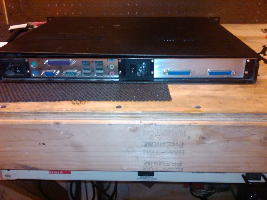
Here are some pics of the main control box.
This one shows the front of the Main case. I like having the 2 USB ports so I can simply bring a thumb drive over and load new G-code. I will replace the serial port for a parallel port and attach a MPG later on.

The computer parallel port will be plugged into the first DB25 port on the right hand side, that will connect to the breakout board on the inside and the other will go to the second control box. I have a second AC power adapter on the right hand side so I can control the coolant pump with the relays on the board.
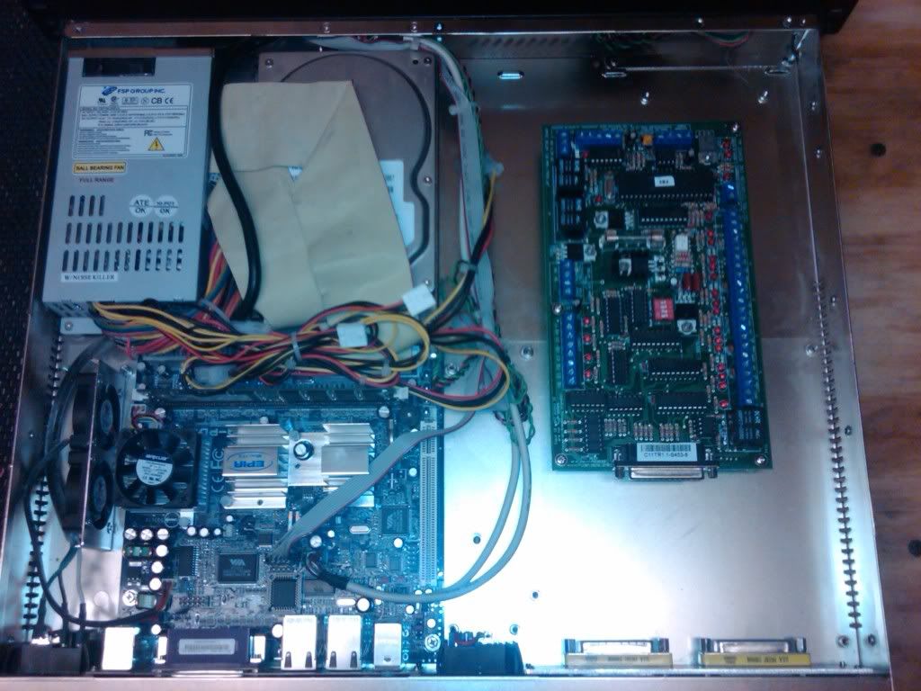
This shows how the inside is laid out but not wired up just yet. The motherboard is a 1Ghz Mini-ITX. Don't need much just to run Mach3. Have been thinking about trying the EMC2 program because Linux doesn't tend to crash like windows but we will see.
-
08-24-2010, 05:28 AM #71
Registered
- Join Date
- Aug 2009
- Posts
- 899
Got the G320X drivers wired up today with the C11T board for a test run and when I turned everything on it sounded like they were going to vibrate to death. After I adjusted the PID on the drivers they were amazingly quiet. I only ran them at 32VDC but even then they had super amounts of torque.
-
08-29-2010, 07:54 AM #72
Registered
- Join Date
- Aug 2009
- Posts
- 899
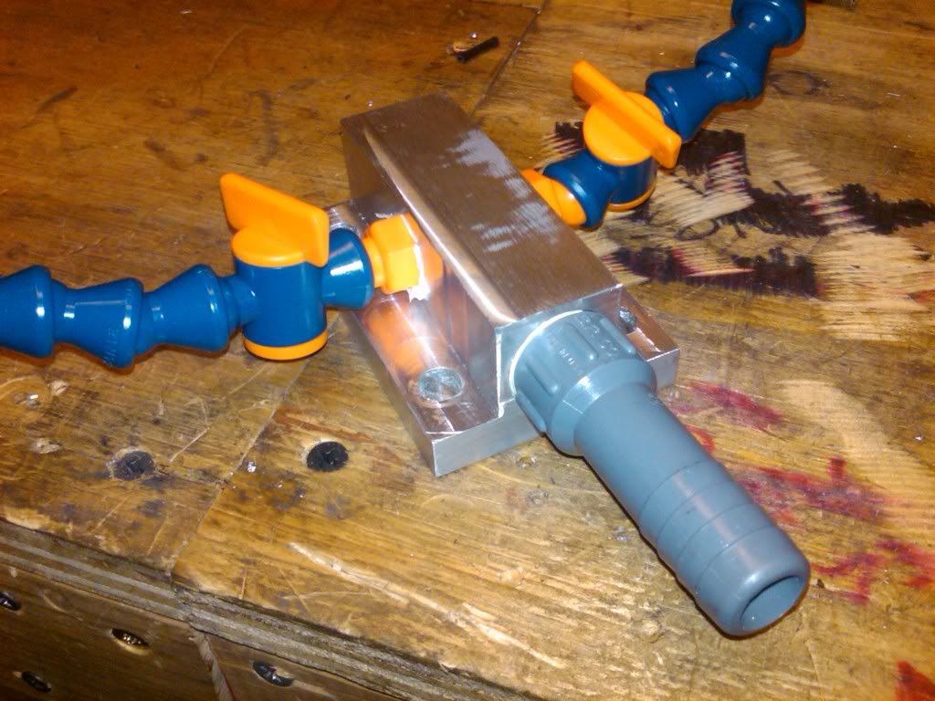
Still waiting on the Lathe to turn the ballscrews (Should be here Wednesday), but have started on the ballnut mounts. I have also received my Loc-Line tubing and have started mounting it to the mill.
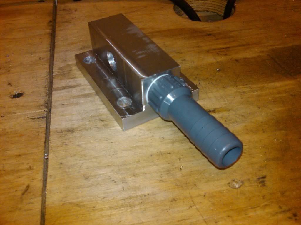
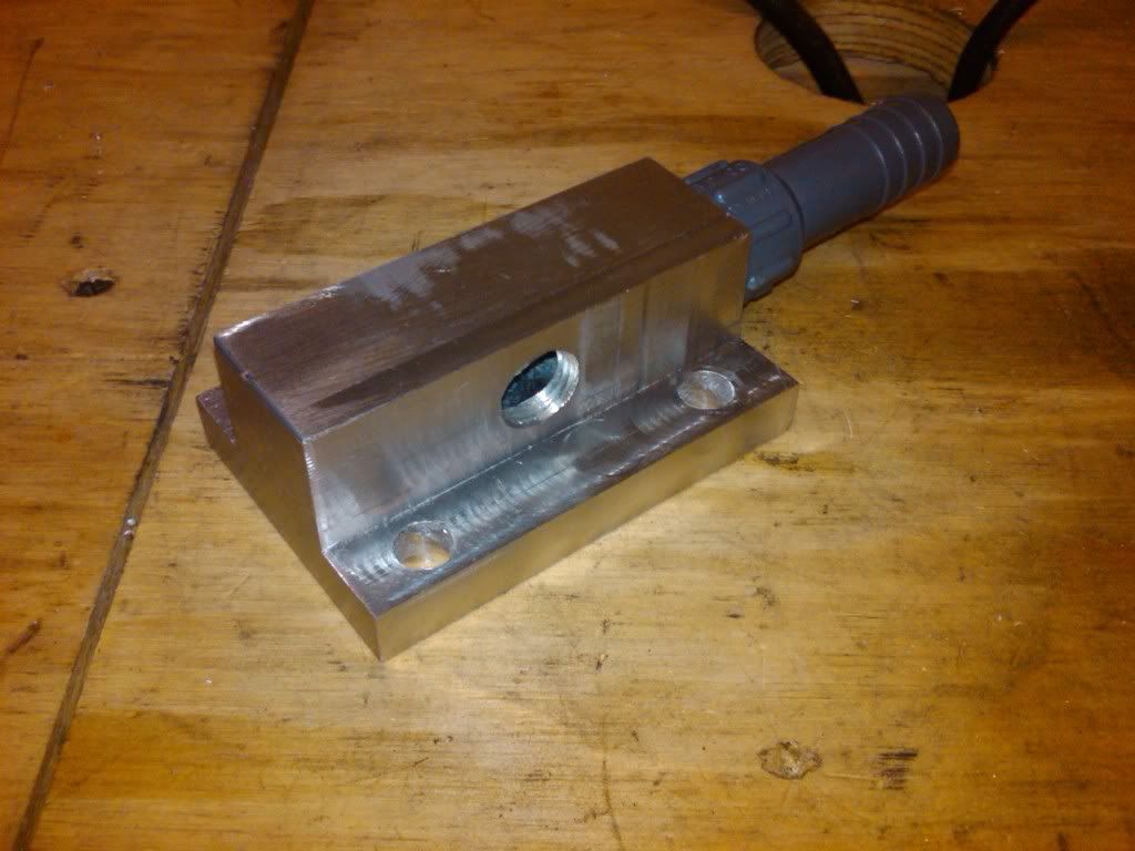
Water bracket with hoses
-
08-29-2010, 08:46 AM #73
Registered

- Join Date
- Dec 2005
- Posts
- 59
Jermie, what ball screw size do you choose for x/y? I'm also converting ZX45. I think RM1605 screws are too tiny. But I don't know if there is enough room to mount RM2005 screws from RMB with two nuts... Can you guys measure how much room is for X axis screw and nuts?
Can't check it now because I'm far away from home:/
-
08-29-2010, 09:12 AM #74
Registered
- Join Date
- Aug 2009
- Posts
- 899
I ordered 3 RM2005 screws at 610mm, 850mm and 1070mm to leave room for machining error, and 2 ballnuts per axis. This is the same thing Flenser ordered and he is also converting his RF-45. I do not have them mounted right now so I cant measure the clearance.
-
08-29-2010, 04:10 PM #75
Registered
- Join Date
- Aug 2008
- Posts
- 962
Manifold looks nice .. where will it mount?
I'm in the process of designing an enclosure for my '45 right now .. getting lots of enjoyment out of my project & watching the others in process on the zone.
I've got a few more miles on me than you do .. but I've found that schlepping these heavy mill parts around is no picnic!
Gary
-
08-29-2010, 06:47 PM #76
Registered
- Join Date
- Oct 2007
- Posts
- 398
Using the RM2005 from LMB and mounting it at the same vertical position as the original lead screw I had less than 0.05" between the X ballnut flange and the bottom of the table. It does fit, though. More on my fumbling around with it here.
Gary, I know what you mean about the heavy mill parts. I'm still recovering from manually mounting the x-table one too many times several weeks ago. I'm a rabid mountain biking addict, and haven't skipped more than 2 consecutive days of riding in years, but I only just now got back on the bike after three weeks. It never occurred to me I was doing anything dangerous : )
-
08-29-2010, 07:18 PM #77
Registered
- Join Date
- Aug 2009
- Posts
- 899
The manifold will mount on the bottom of the head behind the spindle. I am going to make a plate that will cover the gap where the oil drain is located, and mount it on the plate. I have now found that I need a 90 deg fitting on the manifold and not the gray one I have on there now. I guess the down side is if I want to change the oil I will have to remove the plate but it wont be hard to do.
And yes the parts are heavy. I didn't anticipate how much it weighed and the first time I took the X bed off it fell on my arms as I slid it off of the saddle. I still have bruises from it.
-
08-29-2010, 10:19 PM #78
Registered
- Join Date
- Dec 2005
- Posts
- 59
here is some my CAD drawings. Thank you Flenser for link. Now i recall i saw your thread before.
As for y axis double nut on screw: i'm worry that it will reduce Y travel. ??? Milling some flat area for ball screw nuts support blocks is very good idea. I'll try to do it in this way. Did you move Y nut block mounting place relative to original Y nut mounting place?
Flenser what do you mean: "Using the RM2005 from LMB and mounting it at the same vertical position as the original lead screw I had less than 0.05" between the X ballnut flange and the bottom of the table."? I don't get it:/
-
08-29-2010, 11:58 PM #79
Registered
- Join Date
- Sep 2008
- Posts
- 133
Hi
The 2005 x ball nut are a tight fit. This is how we fitted ours.
I had to grind a little of the casting not the mounting area it self but so that the ball nuts fitted down lower enough and a bit so that the bearing blocks stopped rubbing. This has allowed for full travel of the x axis
With the coolant I had some bits left over from a failed z axis drive so i converted it over to a coolant ring....may look a little overboard but it works wellwww.vapourforge.com ..................I recycle electrons.
-
08-30-2010, 01:37 AM #80
Registered
- Join Date
- Oct 2007
- Posts
- 398
I used the original bearing mounts on the ends of the table. The ball screw is pretty much in the same place as the lead screw I removed. You could probably mill a tenth off the saddle and things would fit a little better. Originally Posted by bogus105

The second mount I made for the y-axis fits pretty well. I think I gained a little (0.1") travel, though it doesn't mean much given the fixed distance between the head and the column. Anyway, it mounts in the same place as the original mount for the lead screw.


 Reply With Quote
Similar Threads
-
advice needed
By teamjnz in forum Haas LathesReplies: 2Last Post: 05-20-2009, 11:19 PM -
Advice needed.
By Terence E in forum Community Club HouseReplies: 0Last Post: 05-14-2009, 03:56 PM -
advice needed / to buy or not???
By teamjnz in forum Uncategorised MetalWorking MachinesReplies: 13Last Post: 08-27-2008, 02:48 PM -
advice needed
By trubleshtr in forum CNC Machine Related ElectronicsReplies: 32Last Post: 04-22-2005, 02:48 AM -
Little advice needed
By STUG in forum DIY CNC Router Table MachinesReplies: 1Last Post: 01-26-2005, 02:11 AM
