


Hello,
I thought I'd start a thread about the Mach3 conversion of my 1986 Abene VHF-3 vertical knee-mill. I've mentioned this project in various threads here on CNCZone and I thought that it's about time I'd start a thread on the subject. The project has been ongoing since December '07 and is still ongoing so I'll jump a little between the past and current, I hope that's OK.
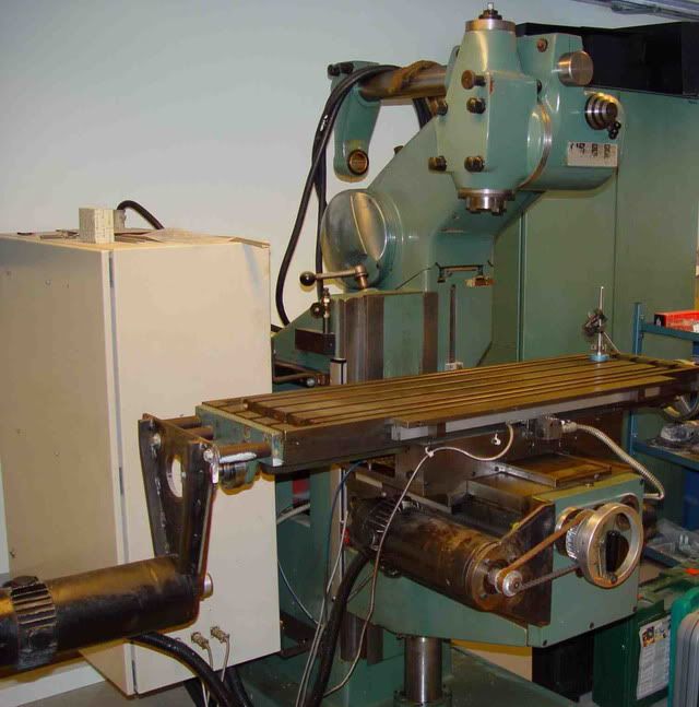
Anyway, I'll start from the beginning. I found the machine on an online advertising site, here's what the photo in the ad looked like:
What I "fell for" was the fact that it already had been converted to CNC by one of its former owners so ballscrews and servos already existed but it lacked the control - a perfect scenario for a retrofit in other words. After some discussions with the seller I made him an offer and he accepted. This was a bit of a gamble since I hadn't actually seen the machine in person but he felt honest so I went all in....
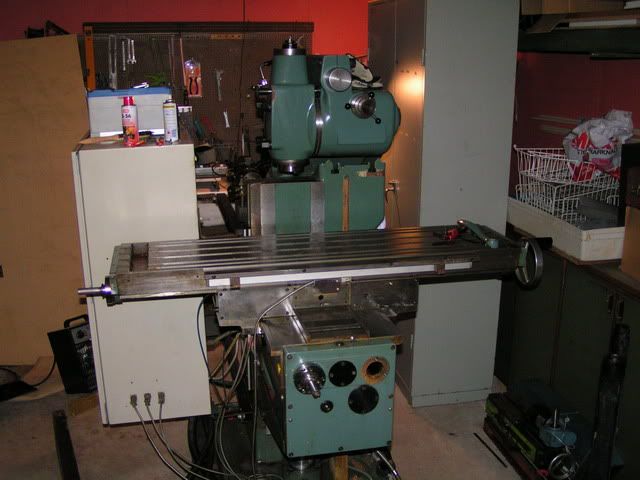
After quite a struggle with the freight company it finally arrived at it's current destination where it sat during the x-mas holidays '08:
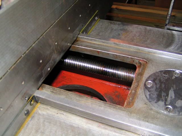
Here's a random shot of the "back" of the Y-axis ways and ballscrew after some inital cleanup.
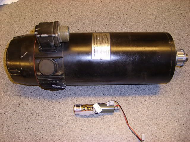
The machine has a 40 taper DIN2080 spindle, 4.5kW (6HP) with a 12-speed gearbox, dovetail slides on X and Z and boxways on Y. The ballscrews are 32mm*5mm rotating in dual tapered roller bearings. The servo-motors that came with the machine are some REALLY solid Indramat PMDC-servos, you can see one of them here, next to a little Maxon DC servo with a 3600line Scancon encoder that I initially planned to use:
The X- and Y axis motors are both of the same type, (MDC10.30D) rated at 19A continous, 150A peak, 0.47Nm/A while the Z-axis motor (MDC10.40C) is a little bit bigger, 24A continous, 200A peak and has an integrated break. I did get the original Indramat 3TRM2 3-axis servo amplifier with the machine and the original plan was to get some Pixie P100 boards from Skyko but I found out that they where no longer availble. Besides, the transformer for the original SCR servo amps was single phase 400V (well, two phase really) and I want to be able to run this machine from a 400V/16A outlet.
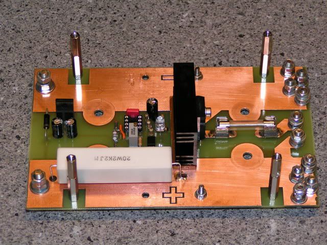
While looking at, thinking about and searching for suitable a drive I started the design of the powersupply. My motors are rated 2000rpm and to get that speed under full continous load I need ~110V at the motor terminals. Some (quite little actually) of the voltage is dropped across the drives internal resistance and a bit more due to the less than 100% modulation of the drive so I settled for 130VDC. Since not yet knowing which drive I would end up using I designed an energydump circuit that dumps regenerative power in order to prevent overvoltage:
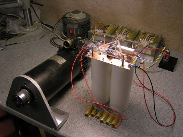
This is a double sided PCB with 105um thick copper on each side, it mounts right on top of the two capacitors. In the background of the second photo above you can see the variac and three transformers I used for testing purposes. You can also see the Y-axis motormount. You might also notice that I replaces the original pulleys with new AT5 profile pulleys. The previous pulleys were mounted with keys and setscrews but I went for those "collet-type-thingies" that clamps to the shaft. (I can't find the correct english word for them at the moment)
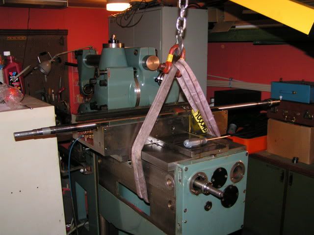
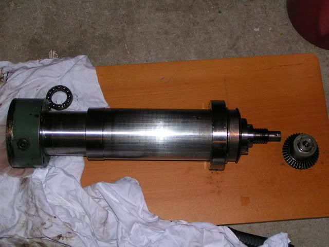
Quite early I found that there was something wrong with the Z-axis on the machine. The knee is driven by a ballscrew and a 2:1 bevel-gear. However turning the shaft sometimes did and sometimes didn't move the knee - something was slipping. In order to remove the screw-jack for the knee I had to remove the table and then hoist the knee up as high as possible with an engine hoist:
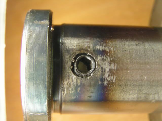
I removed the screwjack and found the problem. The bevelgear was mounted to the ballscrew with a setscrew that was partially recessed into the screw shaft. The problem was that it was recessed too deep making it more like a small tube or pipe than a solid piece of steel.
I ended up drilling, reaming and mounting a solid conical pin right thru the gear shaft and screw instead, I hope that will hold up better that the setscrew aproach.
OK, back to the issue with servo-drives.... I'll simply make a very long story fairly short here and say that disregarded Gecko from the get-go due to low voltage, I thought about Rutex but didn't want to go there due to various reasons. I looked and the Viper200, I tried the Mammut from CNCDrive and the VSD-A from Granite Devices. Although I LOVED the VSD-A it simply couldn't supply enough current. When I'm writing this I'm using the HP-UHU and although the motors are still on the bench I beleive that this might actually work.
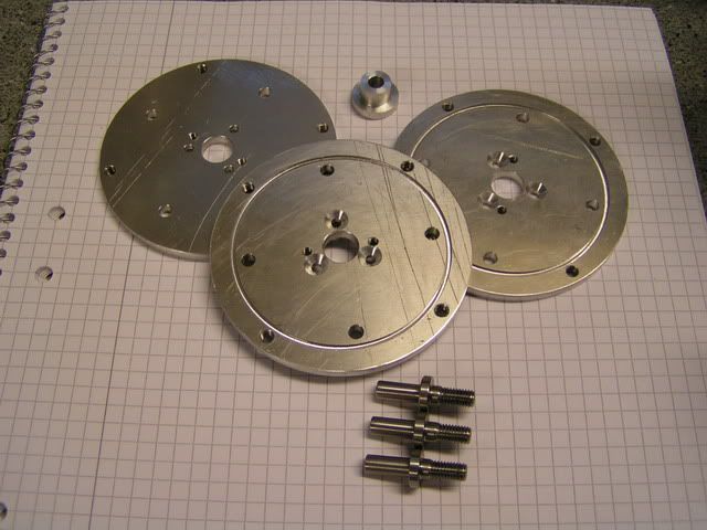
The motors, as stated earlier, didn't have encoders on them so I had to figure out a way to fit those. The back of the motor had the Indramat logo embossed in it so I took them off, chucked them up in the lathe and turned them "clean":
I then fabricated three shafts that fits in the internal thread at the back of the motors as well as three mounting adapters that would let me mount various encoders. The little bushing is an mounting aid to help align the adapter coaxially with the shaft when mounting it to the back of the motor:
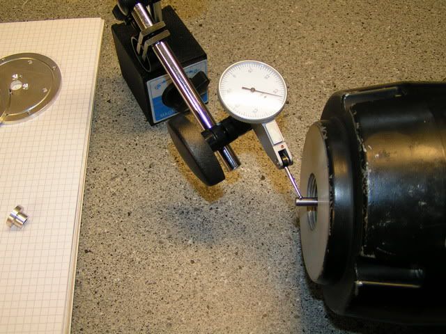
The shaft where mounted and secured with LOCTITE and checked for run-out:
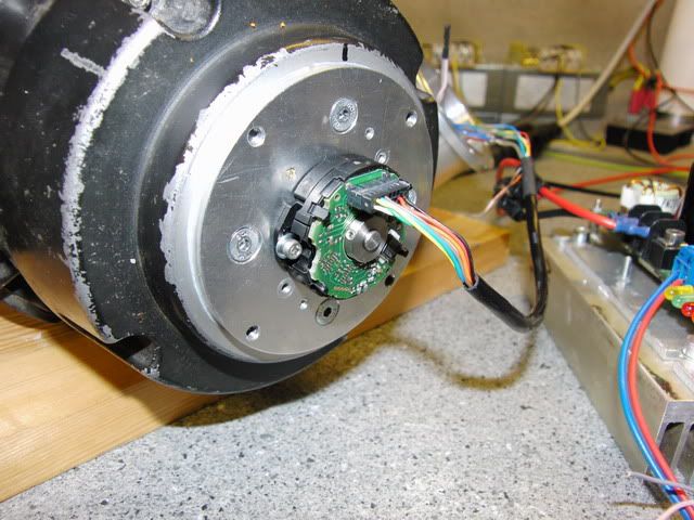
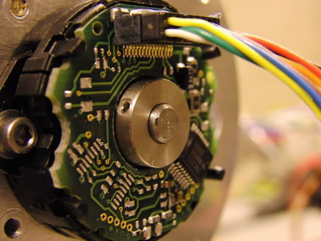
Due to the limited bandwidth of the UHU-chip the nice 3600lines Scancon encoders I had couldn't be used. I ordered up a set of USDigital E7P's and ended up spending another 4+ weeks chasing a noice problem before finally scrapping that piece of s**t and ordered a set of Renco R35i's. With those mounted everything just worked. Here's an overview and closeup of the back of the motor with the R35i mounted:
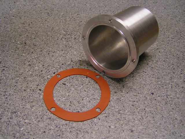
The last photo in this post shows one of the aluminum housings for the encoders that I machined. I made these while the plan was still to use the Scancon encoders so they are a lot longer than needed for the R35i's but it doesn't really matter as there's plenty of room. The groove was originally meant for an o-ring but it turned out that particular dimension, although listed in the catalog i looked in, was a "special" so I made some seals from rubber sheet instead.
OK, that's it for this first post, more later.
/Henrik.
Thread: Abene VHF-3 retrofit.
Results 1 to 20 of 81
-
04-14-2009, 09:52 PM #1
 Registered
- Join Date
- Jul 2007
- Posts
- 887
Abene VHF-3 retrofit.
-
04-15-2009, 12:40 PM #2
Registered
- Join Date
- Aug 2007
- Posts
- 558
Very nice work so far - the machine looks nice and solid and appears to be in great condition. Those servos are enormous

I didn't see the knee lift crank or servo - were those mounted on the opposite side of the knee to the Y axis motor and screw?
This will surely be a very capable machine soon, 40 taper and a 6Kw spindle suggests you'll make short work of some pretty big jobs. I'm looking forward to seeing it come together!
Best regards,
Jason
-
04-15-2009, 01:37 PM #3
Member
- Join Date
- Jun 2006
- Posts
- 475
Very Nice Henrik. Great machine you started with. Looks like it will turn out to be a good machine. Keep up the post's with all your pictures.
Chich
-
04-15-2009, 04:31 PM #4
Registered
- Join Date
- Jul 2007
- Posts
- 887
Thanks guys! The spindle motor is 4.5kW (6HP) not 6kW as I wrote in the first post - sorry about that. I've also been working in it since '07 and not '08 - sorry about that too....
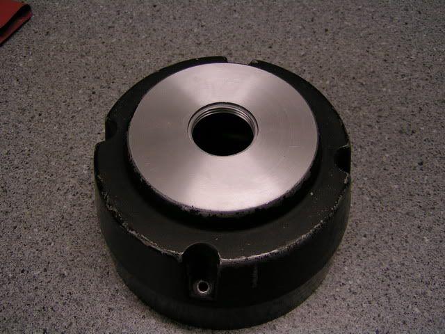
Before being converted to CNC the crank for the Z-axis was coming out of the now empty hole on the front of the knee. The top of the Z-axis ballscrew is under the round cover that can be seen in the 4th photo and now the driveshaft goes perpendicular to that and comes out on the right hand side of the knee. I'll post a photo of it later.
/Henrik.
-
04-15-2009, 05:21 PM #5
Registered
- Join Date
- Jul 2003
- Posts
- 1754
Very nice work!!
I am an emc guy - so I might not be welcomed here... I do have a power stage that seems to be working so far. 160v 20a so far. It takes pwm in (up/down)
http://www.cnczone.com/forums/showpo...&postcount=280
(use at your own risk... )
If you could talk this guy into making a modded version of this
http://www.cnczone.com/forums/showthread.php?t=74532
to output pwmup/down.... You could do step/dir.
Or switch to emc2 Come on - you know you want to...
rigid tapping anyone?
anyways.. again - nice work.
edit Or - look at the HP uhu drive (duh)
sam
-
04-15-2009, 06:30 PM #6
Registered
- Join Date
- Jul 2007
- Posts
- 887
Hi Sam,
You're more than welcome here! Believe me, I've been following your work with the PWM amplifier, you've done some really nice work with it! Right now, as you might know, I'm going for the HP-UHU drives. After struggling quite a bit in the beginning we (Kreutz, Paul, Irfan, Joszi, me and a few others) seem to have worked thru the small issues that was discovered initially and my drives have been working very nice since then. Again, still on the bench though....
Here's a photo where you can see where the drive shaft for the Z-axis screw will come out:
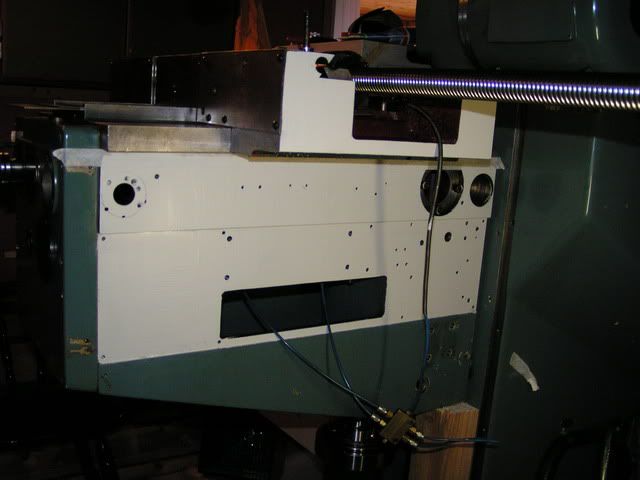
Because the shaft is so close to the Y-axis ways the large 60 tooth pulley won't fit without the saddle hitting it on its way towards the back of the machine. This had been solved by using a two stage belt transmision, first 2:1 to get the reduction and then a 1:1 up to the drive shaft. I'll do it the same way but with new mounts, pulleys and belts. Oh, I decided to put some paint on the bare metal surfaces on the side of the knee and sadle so the white layer in the photo is just the primer.
As of today this is pretty much where I am with the actual machine. This weekend I'm planning on lifting the machine off of the pallet and putting it in a somewhat more permanent position where I can actually test and perhaps even use it some time in the future. A lot more work has been done on the control-side of the thing though.
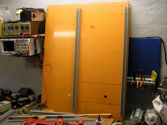
I ripped out what was left of the old control and took the back-plate out of the cabinet so it would be easy to mount all the new goodies:
Here's a photo from the beginning stages when I was still playing with the VSD-A's. I got a new 400/90V, 4kVA 3-phase transformer that gives me a nice "sturdy" 130VDC:
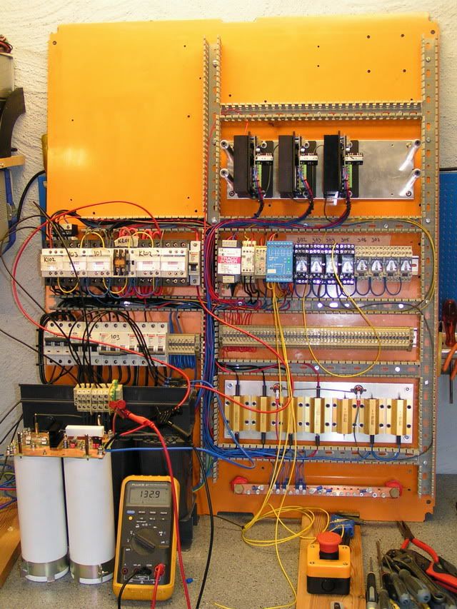
You can see a bunch of power resistors in the above photo. Three of them are for softstarting the 4kVA transformer, one is for softstarting the DC-side, one is for discharging the powersupply and two (in parallell) are used for the regenerative braking circuit.
Next photo is a more recent one:
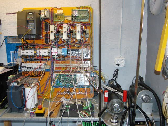
The VSD-A drives have now been replaced with three HP-UHU, there's a nice Siemens MicroMaster440 VFD for the spindle motor, a C11 breakoutbard, a CUBLOC PLC-board and a few other goodies. In front of the panel is the Smoothstepper and to the left you can see all three motors - it all works :-)
The next photo shows the control panel I designed for this project:

It features a 17" TFT screen with touch overlay, a nice MPG wheel and a bunch of 22mm pushbuttons. The buttons are interfaced to the CUBLOC which in turn talks to Mach3 over MODBUS, this gives me quite a bit of flexibillity. For example, I've set it up so the CycleStart button only start the program execution if I am on the Program Run screen in Mach3.
I'm also working on my own screenset that will help running the machine with the touchscreen, here a screenshot of the Program Run screen (Auto):
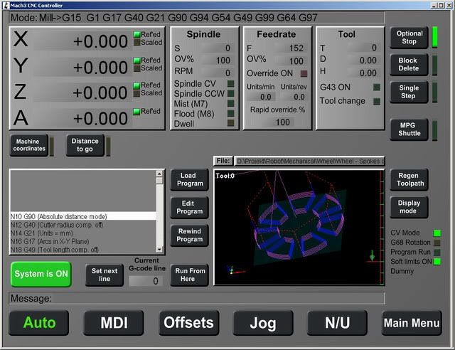
So, now I've pretty much covered what has been done on the project as of today. Obviously there are A LOT of small things and details but I leave that for later or untill someone asks.
Thanks!
/Henrik.
-
04-15-2009, 07:03 PM #7
Registered

- Join Date
- Jan 2007
- Posts
- 219
Looks Great! I am curious though, What are all the relays and contactors for? I also see alot of din mount devises, but I am unable to make them out in the pictures. Maybe you could do a little youtube video and show us full control?
The console looks great by the way. The 17" touch-screen will be great to use. Is it a resistive or capacitance type touch panel?
-Adamwww.adambrunette.com - Converting My Harbor Freight X2 And My Jet Jvm-830 Knee Mill, As well as many other projects.
-
04-15-2009, 08:02 PM #8
Registered
- Join Date
- Jul 2007
- Posts
- 887
Thanks Adam!
Starting at the top, next the VFD is a powersupply used for the low voltage side of servo-drives and only for that. Next to that is another powersupply, 5VDC that powers the "machine side" of the break-out-board, MPG, etc.
Further to the right is the fault-interface for the servo drives. The HP-UHU fault I/O functions much like it does on the G320 - You connect them together and if one drive faults they all stop. The drawback with this is that you don't know which one caused the fault from the start. This circuit and the CUBLOC solves that part for me.
Below the VFD are the contactors, here's what they do:
** Switches power to the VFD
** Switches power to the transformer
** Bypasses the softstart resistors on the mains-side of the transformer.
** Switches the DC between the rectifier and capacitorbank
** Bypasses the softstart resistors for the DC-side.
That's five, the last one is a spare :-) I may have gone overboard with this aproach of cutting and softstarting BOTH the AC and DC side but I want this machine to be as safe as I can possibly make it.
On the right hand side of the contactors is another powersupply, this one pretty much powers everything else in the control (24VDC). Next to that is a timing relay for the softstart and next to that is a phase and voltage supervising relay.
The blue thingie is a Duelco NST-8 emergency stop relay. This is what stops and starts the system, every safety function is connected in series with this and it also supervises the large contactors making it impossible to reset if any of them is stuck closed etc.
Then comes a bunch of relays.... These are mostly for safety and supervision of the system and are connected in series with the E-stop. One relay is for servo motor overheat (thermal switches inside the motors), one is for servo drive overheat, one for limitswitchesby, one for the servo drive fault interface and so on. This E-stops the system in case anything goes wrong while secondary contacts on the relays drives the inputs on the CUBLOC so it can tell Mach3 what is wrong. Mach3 can then tell ME thru the Diagnostics screen:
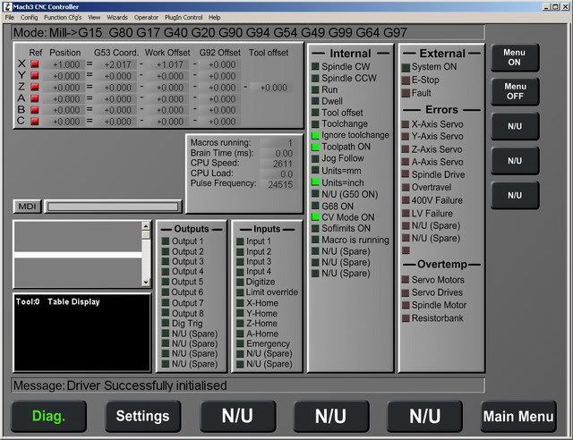
Another relay is for the Z-axis break and yet another for bypassing the limit-switches. There's a lot of things going on....
I hope that brings some more insight to it.
/Henrik.
-
04-15-2009, 08:25 PM #9
Registered
- Join Date
- Jan 2007
- Posts
- 219
Wow! I guess it wont be able to do anything wrong without you knowing. LOL. How are you controlling the VFD? Are you using the 10V output of the C11 or something else? How about index pulse of the spindle?
Also, The console looks great. Is the computer mounted inside it?
-Adamwww.adambrunette.com - Converting My Harbor Freight X2 And My Jet Jvm-830 Knee Mill, As well as many other projects.
-
04-15-2009, 09:08 PM #10
Registered
- Join Date
- Jul 2007
- Posts
- 887
Hi,
I'm sure it can act up just as much as any other machine and in ways I haven't yet thought about. Besides, the more "toys" you add the more stuff is there to fail so it's sort of a balance act. That's why I want to make as sure as I possibly can that it WILL stop when hit the E-stop button.
The VFD isn't fully integrated yet but yes, the plan is to use the analog output on the C11 board. I haven't thought about the indexpulse yet. The spindle speed PID in Mach3 seems to not work that great (judging from messages on the Yahoo-group) can it be used for anything except spindle-speed readout?
No, the computer is not in the console, it's a separate box and will hang on the inside of the cabinet door.
Thanks again for the kind words!
/Henrik.
-
04-16-2009, 11:36 PM #11
Registered
- Join Date
- Jun 2008
- Posts
- 228
[QUOTE]
You can see a bunch of power resistors in the above photo. Three of them are for softstarting the 4kVA transformer, one is for softstarting the DC-side, one is for discharging the powersupply and two (in parallell) are used for the regenerative braking circuit.
[QUOTE]
Hi Henrik,
Softstart a transformer? Hey, that's just what I am looking for. Sometimes the high current, when flipping the transformer switch, kicks out my cirquit breaker.
I really would like to be able to softstart my 15 KVA 380V 3-phase -> 220V 3-phase transformer. Can you please explain how to do it and what components to use?

/Peter
-
04-17-2009, 04:30 AM #12
Gold Member
- Join Date
- Dec 2004
- Posts
- 1865
 Control panel, extra nice.
I am in the design stages of a control panel for my lathe conversion and this is very similar to what I envisioned.
Control panel, extra nice.
I am in the design stages of a control panel for my lathe conversion and this is very similar to what I envisioned. Originally Posted by H.O

I am thinking 15" screen because of my space limitation, but it is nice to see what other people are doing.
:cheers:Nice work Henrik!!!:cheers:Warning: DIY CNC may cause extreme hair loss due to you pulling your hair out.
-
04-17-2009, 06:37 AM #13
Registered
- Join Date
- Jul 2007
- Posts
- 887
Hi Peter,
The principle is very simple, when you turn on the power to the transformer you run the current thru a resistor (or three resistors, one for each phase). This limits the inrush current. After a short delay you use a contactor to bypass/short these resistors.
There are different ways to do this and the way to choose depends on the particular application. If you have 3*400+N on the primary side of your transformer the absolute easiest way is to get a contactor with a 230V coil and integrated delay module. I'm using a Telemecanique LC1-D32 contactor with a LA4-DT timing module like in the attached schematic.
I hope this makes sense.
/Henrik.
-
04-17-2009, 09:07 AM #14
Registered
- Join Date
- Jun 2008
- Posts
- 228
Thanks Henrik,
I see, it is just using Ohm's Law for a short period to lower the current peak.
In my case I have L1,L2,L3 + PE, no N so I don't know about using PE for the 230V contactor. Maybe I should get one with a 380V coil?
My machine also has a Power Monitor that checks the 3 x 230V. It "clicks" after a few seconds. I guess it is delayed a little before checking the voltage. This means that I must set the soft start delay shorter than that in order to be "ready for the voltage test" earlier, right?
Can you please advise the specifications and source for the 3 resistors?
What W-rating? etc... I guess they are beefier for a 15 kVA transformer than for a 4kVA one?
/Peter
-
04-17-2009, 12:01 PM #15
Registered
- Join Date
- Jul 2007
- Posts
- 887
Hi Peter,
I would definetly NOT use PE for ANYTHING except PE. A contactor with a 400V coil would work if the timing module can take it. I think that the timing module I used is quite universal and works with anything from 24VDC to 240VAC but I'm not sure about 400VAC. I'm sure they exist though.
Actually, the size of the transformer doesn't make that much difference in this case. The pure resistance in the copperwire is pretty much near zero anyway (which is why you need the softstart...)
I'm using 47ohm/100W resistors (ELFA 60-681-67). This works well because the initial current transient only lasts for a VERY short time (milliseconds) - as soon as current start to flow thru the transformer the magnetic field starts to build and the current decreases - and these wirewound resistors can take massive transients.
A delay of 1s is more than enough.
/Henrik.
-
04-17-2009, 01:46 PM #16
Registered
- Join Date
- Jun 2008
- Posts
- 228
Henrik,
Thanks again.
I checked the resistors at ELFA and they are 100 SEK ea. which is OK.
I will check my power cable to see if it has an N-wire that I can use. if that is the case, I can use 230V for both the delay-relay and the 3-phase contactor that will be required as well.
I have one more question about soft-starting a transformer, but it is about a TIG welder, so I have it in a new tread so not to distroy this thread with welding topics.
http://www.cnczone.com/forums/showth...358#post600358
/Peter
-
04-17-2009, 05:52 PM #17
Registered
- Join Date
- Jul 2007
- Posts
- 887
Hi,
If going for a contactor with 230VAC coil you need to make SURE that the Neutral is connected. Not only in the cable but also in the socket or panel where you connect. If it's not there the bypass contactor will never engage and you will probably smoke the resistors.
You can use a contactor and a separate timing relay it will work the same and might give you some more flexibility. The nice thing about the Telemecanique stuff is that the timing module is mounted directly on the contactor making it a single DIN-rail unit.
/Henrik.
-
04-17-2009, 10:59 PM #18
Registered
- Join Date
- Jun 2008
- Posts
- 228
No worries Henrik,
I built a modern house (2002) and it has all 5-wire electrics. The cable from the cabinet to the outlet for the machine is a heavy duty 5-wire cable with L1,L2,L3, N, PE all connected. But, damn, the machine builder only supplied a 4-wire (L1, L2, L3, PE) 8mm2 rubber cable to the transformer. So If I want to do the soft-start set-up I need to either get 400V relay, delay module and contactor or get 6m of 5-wire 8mm2 rubber cable. It is leaning towards the 5-wire cable and 230V relay, delay module and contactor.
Now I know at least how to do it when I get the right bits.
And the old 4-wire cable is not a complete waste. It can be used for a soft-start setup for a TIG-welder that only had a 3-wire cable. It must have been a "cheap cable" conspiracy back in the nineties.
Thanks again Henrik
-
04-18-2009, 01:08 PM #19
Registered
- Join Date
- Jul 2007
- Posts
- 887
Hi,
With the help of a friend I've now got the machine on adjustable feets on the floor instead of on the pallet. Since I don't have access to any heavy duty lifitng gear (crane/forklift etc) I've been thinking about how to actually do this for quite some time.
What we ended up doing was to use two large crowbars to just slightly lift one side of the machine at the time and sliding in a thin piece of well lubricated sheet-metal between the pallet and the bottom of the machine. We then lined up the pallet jack, lubricated the forks and "simply" pushed the machine from the pallet onto the pallet jack using the crowbars and a bit of elbow grease. This gained us access to the four mounting holes in the corners to mount the adjustable feets. The gauge on the pallet jack showed 1200kg (2600lbs) without table, sadle, motors and control-cabinet. It all went smoother than I initially thought, all in all a very good saturday morning.
Next step will be to borrow a machinist level and adjust all the feets so the machine is nice and level. Then it's on to installing the electrical panel in the cabinet.
/Henrik.
-
04-20-2009, 06:19 PM #20
Registered
- Join Date
- Jan 2005
- Posts
- 1050
SO henrik here you are - I am just waiting to see this work - are you implementing the auto tool changer for this mill -
also would like to know more on the Cubloc thingi you are putting on -
for other folks Henrik has put a lot of effort in getting the HP UHU to work - and a part of the credit goes to him - here are the HP UHU threads one and two
My best to you henrik -
RGDS
IRfan


 Reply With Quote
Similar Threads
-
Jet 830 CNC Retrofit
By Adamj12b in forum Knee Vertical MillsReplies: 12Last Post: 12-22-2009, 08:41 PM -
Sieg X1 retrofit with Linux EMC2, CNC Fusion retrofit kit and Gecko G540
By GreenLead in forum Benchtop MachinesReplies: 31Last Post: 11-27-2008, 06:55 AM -
camsoft retrofit to a anilam crusader retrofit
By bowlingmac in forum CamSoft ProductsReplies: 44Last Post: 07-25-2008, 03:00 AM -
Retrofit a HXL
By bartL in forum Hardinge LathesReplies: 0Last Post: 05-24-2008, 07:05 PM -
Retrofit of Not SMB-1
By Mickey_D in forum HURCOReplies: 0Last Post: 07-29-2007, 05:52 AM
