


Sorry, forgot a picture.
Results 201 to 220 of 900
-
05-19-2011, 11:58 PM #201
 Registered
- Join Date
- May 2011
- Posts
- 0
-
05-20-2011, 07:11 AM #202
Registered
- Join Date
- May 2007
- Posts
- 102
Tell me , where did you buy this board . Originally Posted by tanglewoods

Seems like an upgraded version to me .
-
05-20-2011, 10:36 AM #203
Registered
- Join Date
- Oct 2007
- Posts
- 9
TB6560-T4-V4.
Google Translate
-
05-28-2011, 08:50 PM #204
Registered
- Join Date
- May 2007
- Posts
- 102
Fixes to my board :
1) Resoldered all driver chips . The soldering wasn't bad at all , considering
a chinees board . Resoldered them anyway , using leaded solder .
Makes a bright shiny solder instead of a dull gray one .
2) I noticed the traces from the sense resistors are very thin considering the
full stepper current has to pass trough them . So I added a wire , to each
trace , from the chip directly to the sense resistor .
4 wires on each side . I doubt these traces will cause problems , but I
added the wires just in case .
3) Removed the current limiting circuit . Not only the resistor but also the
capacitor , and the trace going to the transitor . Open ended traces can
act as antenna's and pick up noise .
4) Added the 74HC14 to fix the clock signal . I removed one of the 74hc14's
, and also removed the bad quality sockets . One chip was then soldered
directly to the board , the other one replaced with a decent Q socket .
To that socket I added a daugtercard containing the 2nd original 74HC14 ,
and a 3'd one wich is used to fix the CLK signal .
4 pairs of wires are then connected to the CLK trace , wich was cut per
the instructoions in a previous post .
5) To fix the 7812 and 7805 getting hot , I' 've added an inline resistor .
This is an ugly fix as it simply shifts the problem from one side to
another . Now the resitor will get hot .
A step down convertor , or a separate 12V supply would be far
better . But that's beyond the scope of an easy fix .
6) Finally I replaced all 8 sense resistors with the right ones . I think this is
very important . The datasheet clairly states the motor current has
to be set with the resistors . Not with the torque control pins .
So I needed 1Amp/phase , wich comes down to 0.5 Ohm . 0.470 Ohm is
the closest value .
Now with both current dipswitches set to maximum , I can run the board
at 31.5 V with nema 23's . No problem at all , drivers don't even get
warm . No hissing sounds , running very smoothly . Tomorrow I'll hook up
a pulse generator to measure motor rpm ; but it's very high . Especially at
31.5Volt wich is the maximum my supply can deliver .
So folks , apart from the fixes described in nrs 3 & 4 wich are a must to
get this board talking , I strongly advice to fix the resistors as well . It's
easy , it costs only a few pennies more and it's well worth the effort .
I've bought this board for 30€ s&h included . Spend 3.20 € buying parts and
half a day's work to do all the modifications .
That's a 4 axis driver for less then 35€ ( less then 50$ ) .
Just try that with gecko's
-
06-04-2011, 09:42 AM #205
Registered
- Join Date
- Dec 2010
- Posts
- 70
Hi folks,
I have one of this boards, 4 axis, which is driving me crazy!
It is dead! Initially one TB6560 (z axis) IC was "crashed". I supposed some wrong manipulation of stepper's cables/connectors (coupling or uncoupling steppers with power on). Until the new IC will arrive I intended to use the A axis as Z axis. So far, so good. For now I only need 3 axis. This was happen 3 or 4 days ago.
After that, until now the whole machine as worked without problems.
Today, one hour ago, I came to the workshop and power "the toys".
First time when I tried to move the Y axis I heard a bad noise from the stepper.
I powered off the whole system and check for mechanical problems. Nothing abnormal there.
I checked (with an ohmmeter) the controller's Y outputs and one pin is "grounded". Exactly like the previous IC from the Z axis.
I guessed the Z axis IC was "crashed" by me, playing wrong with cables/connectors but the second IC (Y axis) was crashed by itself. I doesn't touch any cable/connector.
Any hints? Something to recheck? The power supply is a switched-mode power supply, taken from a big copy machine or big printer, something like this. It have 24v and 18A and is very stable (used for over 4 months without problems).
The steppers are 3NM with 3A.
I'm really tired playing with this piece of s**t. Please, recommend me some alternative bob/drivers. I really need something which really work.
Thank you!
-
06-04-2011, 03:41 PM #206
Registered
- Join Date
- Dec 2010
- Posts
- 70
It's me again:
It is somehow possible to force the TB6560 by setting a higher frequency, after putting 100pF capacitors?
-
06-04-2011, 05:15 PM #207
Registered
- Join Date
- Apr 2010
- Posts
- 0
Interzis, All,
After extensive research and modification to my control boxes (two machines) I was able to solve ALL my TB6560 problems. Please follow my instructions below to the letter and I guarantee you'll have the same success...
1) Remove TB6560 from machine
2) Install Gecko G540
All problems with the TB6560 solved. By the way I still have two boards for sale if anyone wants one of the pieces of Cr@p...... They're fine for woodwork that you can reset zero after each piece, but metalwork is HIGHLY NOT recommended. I snapped more carbide bits and ruined more parts than the cost of 10 geckos... They are WELL worth the price to work WITH your machine and not ON it.
Cheers,
Jeff
-
06-04-2011, 05:26 PM #208
Registered
- Join Date
- Dec 2010
- Posts
- 70
I have to admit you are just right!
-
06-05-2011, 10:26 PM #209
Registered
- Join Date
- Feb 2011
- Posts
- 102
 Board non-functional after "repair"
I tried to fix my 4 axis TB6560 board per the instructions here. Now just makes a hissing noise or moves fitfullly. If it moves usually more than one axis active despite only moving one on the controller. I went over and over the schematics and posts here. I know I made the circuits correctly. I have to admit my soldering skills are beginner level though, but I cleaned and inspected everything and there are no shorts. WTF? I can post some pictures of my work if anyone is interested in one on one help, otherwise I'm saving up for some better boards.
-
06-06-2011, 12:01 AM #210
Gold Member
- Join Date
- Jan 2010
- Posts
- 2141
Do you have access to an oscilloscope (or a friend with an oscilloscope)? Originally Posted by Mike4703
If not, do you have access to a multimeter?
Did the board work properly before you made the modifications?
Can you provide info about the stepper motors that you are using, the power supply that you are using, and what DIP switch settings you are using?
Edited to add:
I just saw your post at http://www.cnczone.com/forums/genera...ontroller.html
Are you driving this board with Mach3 directly from the parallel port, or are you driving a parallel port breakout board which then drives the TB6560 board?
-
06-06-2011, 12:29 AM #211
Registered
- Join Date
- Jun 2010
- Posts
- 178
I fixed my problem with the 203V's. Won't ever look back.
Originally Posted by jmchris
-
06-06-2011, 06:46 AM #212
Registered
- Join Date
- Feb 2011
- Posts
- 102
doorknob-
The steppers are the ones carried by Sherline for the 5400 mills. They are #23 size made by Shinano, Kenshi 2amp/phase. I'm using a 24v power supply. They did work with the little pendant controller that will run the axis at one speed, one at a time. However never could get it to move with the MO-501CON CNC controller. While researching this problem I came across the thread here, and decided to do these fixes to make sure it wasn't the known problems with the board. I don't have an oscilloscope but would considering buying one if one of those inexpensive handheld 10Mhz single trace would do the job. No experience actually using one, but understand the theory well, and want to learn more. I do have a multimeter. The dip switches settings have been all on or #2 off for 1/2 stepping. The whole idea of this project was to do my designing and programming inside on my good laptop, load the g-code into a flash drive, take it out to the shop and plug it into the MO-501CON controller and make parts.
-
06-06-2011, 06:56 AM #213
Registered
- Join Date
- Feb 2011
- Posts
- 102
doorknob--to answer the second part:
The MO-501CON connects to a breakout board that puts out step, direction, enable signals for each axis. I have tried connecting these to both the 15 pin manual connecter and the 25 pin connecter with no result. I have not tried to connect it up directly to Mach 3 as I don't have a computer with a parallel printer output.
-
06-06-2011, 07:08 AM #214
Registered
- Join Date
- Dec 2010
- Posts
- 70
thanks lukewarm, thanks jmchris, I'll order a Gecko ASAP.
203v sounds good but for now is too much for me (and too expensive)
I'll order a g540. unfortunately I have to order it directly from U.S. because european prices are almost doubled
thanks again
-
06-06-2011, 02:11 PM #215
Gold Member
- Join Date
- Jan 2010
- Posts
- 2141
An oscilloscope, even a low-end model, would permit you to verify that you are getting the step pulse out of the breakout board and into the TB6560 board, and it would permit you to examine the signal at various points within the circuitry of the TB6560 board (for example, to verify that the step pulse is making it through the optoisolators). Originally Posted by Mike4703
What is the polarity of the enable signal coming out of the breakout board? (You can measure that with a multimeter.) Some breakout boards have jumper settings that can select the proper signal polarity - have you checked all of the jumper settings?
Are you certain that you have the proper voltage applied to the breakout board? Some of them need a separate +5 volt power supply (generally taken from a USB connection to the computer).
Am I misunderstanding how you have the breakout board wired? I don't really understand the details of the MO-501CON setup.
-
06-07-2011, 12:00 AM #216
Registered
- Join Date
- Feb 2011
- Posts
- 102
Ok, next Friday I'll pick up one of those handheld scopes. CNC may be part of my life for a while so it'll come in handy, and I'll learn something. Your last question brings up problem that may be due to my lack of experience with the hardware. The CNC controller which runs the G code is connected to a breakout board by a special cable. The board only needs a 24v source, it makes it's own 5v for the logic circuits. This breakout board has outputs terminal labled +5v, pulse, direction, and shield for each axis. I figured I could adapt this output to the TB6560 before I bought it, but these labels don't match up with the LPT output labels. However its all 5v logic so it tried just jumping from them to the similar input pins on the TB6560 LPT socket. No go. I'll check the polarity of the enable signal coming out of the breakout board when I get back home. I'm traveling all week and won't be back home until next weekend.
-
06-07-2011, 10:30 PM #217
Registered
- Join Date
- Jun 2011
- Posts
- 0
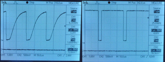
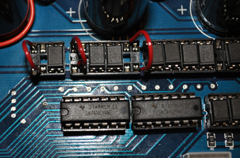
A simple fix for the clock problem
A simple way to fix the driver ic clock problem is to remove the opto-coupler for each clock line and place a jumper wire in the dip socket to connect the 74HC14 to the clock pin directly. The only caveat is that clock lines from the parallel port won't be optically isolated from the driver anymore. I've got the 5-axis board and only using 3 of the axis so I only jumpered 3 of them. Check out the before and after oscilloscope waveforms taken at the clock pin of the TB6560 chip. After adding the jumpers my machine runs fast without losing steps.
-
06-07-2011, 11:55 PM #218
Gold Member
- Join Date
- Jan 2005
- Posts
- 1695
If you're having trouble with missing steps, try changing the polarity of the step and dir signal in Mach. Also try changing the pulse width to 5uS. This will give the board time to respond.
If you're motors vibrate and stall at higher speeds, add a vibration damper. All the motors I tried so far has benefited substantially from this.
-
06-08-2011, 07:23 AM #219
Registered
- Join Date
- May 2007
- Posts
- 102
Originally Posted by Karl_Williams
This fixes the rise time allright , and it certainly is an easy fix .
But this setup still drives the TB6560 with an active low signal .
Meaning the rising edge isn't the leading adge as it should .
If you remove the opto , I 'de say invert the signal in mach3 to get it active high . This will cause the axis leds not to function .
If you want it all , you'll have to insert a 74HC14 between the opto , or jumper and the tb6560 .
Did you also remove the current limiting circuit ?
Pat
-
06-14-2011, 11:28 PM #220
Registered
- Join Date
- Oct 2010
- Posts
- 65
Thanks for this info Karl
Removing the opto chips and adding a bypass wire really worked well to increase the speed, I also completely removed the caps, on /(pin7) which instantly removed all the terrible noise it had, I did not have any caps to replace them, but the drive works extremely well without them,? (I am not an electronics guy, and I really don't care if I smoke this drive,) it works good enough without them, when I find some 100pf I will add them,
I found I needed to also remove and bypass the direction opto's as well, as it was still missing steps with them, I only left the 4 enable opto's in
The 4 axis board I have is running very well now, no missed steps, no noise, and good speed with power, done with only these two modifications without these mods, the board was 100% useless,
what would make this board much better, is a variable current, and variable decay setting instead of dip switches, this would allow much more fine tuning.
No question this board is cheap, and mistakes were made in chip selection, and or design which seem to vary from board to board , I probably would not recommend it as your daily driver, but certainly worth it as a backup, or a cheap driver, Only if your willing to take a chance at fixing it
Originally Posted by Karl_Williams

 Reply With Quote
Similar Threads
-
Chinese 3 Axis TB6560 & 300oz @ 24V too slow and not enough power
By KallDall in forum Stepper Motors / DrivesReplies: 12Last Post: 09-28-2016, 06:20 PM -
New (red version) of TB6560 chinese driver board
By hspalm in forum Stepper Motors / DrivesReplies: 19Last Post: 02-23-2014, 01:34 AM -
soc-robotics MK4cp OR chinese TB6560 driver
By 24ariel3 in forum Stepper Motors / DrivesReplies: 2Last Post: 04-09-2013, 04:24 AM -
Maximum Voltage with Chinese TB6560
By riphet in forum Stepper Motors / DrivesReplies: 9Last Post: 10-16-2012, 05:29 AM -
Just got my updated super Pid controller
By msimpson99 in forum DIY CNC Router Table MachinesReplies: 13Last Post: 12-22-2010, 10:35 AM
