


Noise comes from lots of things; we know that already, data wires are what picks up this noise and causes havoc to the very sensitive Parallel port.
Now if we think about it, no professionally made machine has data wires running all over the place like most hobbyists insist on doing, if we don’t have data wires, then we don’t have problems with noise.
Ok, how.
Motor wires create noise, but not affected by it, so we can save on the shielded wire here.
Limit switches are nothing more than a safety switch, so why not wire it up like one,
One or two E-stop switches and all limit switches, all wired in series (24 volt), no problem with noise, again shielded wire isn’t needed.
Home switches (wired parallel) of any type can be found in (24 volt) versions, again no problem with noise, no shielded wire.
E-stop and limit switches should always have their own hard wired circuit fully independent of the computer, but it is also an advantage if the computer receives the E-stop signal as well.
In the control box the E-stop circuit uses a large relay, by having another small 24 volt relay connected in parallel very close to the breakout board, now it’s here we have data wires, very short, no problem with noise, no shielded wire, and we do the same with the home circuit, another small 24 volt relay.
PS:
Limit switches are something you don’t run into every day; in fact you shouldn’t touch them at all,
just like E-stop they should be wired closed (the safest way), a strong switch with a solid ramp that can force open a sticking contact, wired this way a loose contact or a broken wire will create an E-stop.
Results 1 to 9 of 9
-
01-23-2011, 10:50 AM #1
 Registered
- Join Date
- Jun 2006
- Posts
- 47
How to build without shielded wires.
-
01-23-2011, 02:59 PM #2
Community Moderator
- Join Date
- Mar 2003
- Posts
- 35538
The main problem is that there's not an inexpensive method of using 24V for switches.
Gerry
UCCNC 2017 Screenset
http://www.thecncwoodworker.com/2017.html
Mach3 2010 Screenset
http://www.thecncwoodworker.com/2010.html
JointCAM - CNC Dovetails & Box Joints
http://www.g-forcecnc.com/jointcam.html
(Note: The opinions expressed in this post are my own and are not necessarily those of CNCzone and its management)
-
01-23-2011, 03:47 PM #3
Registered
- Join Date
- Jun 2006
- Posts
- 47
 Originally Posted by ger21

All switches (E-stop), relays and wiring involved in a 12-24 volt circuit are standard off the self (cheep) easy to find components, whereas shielded wires of the type needed for CNC work isn’t cheep at all, if you can find it.
-
01-23-2011, 05:13 PM #4
Community Moderator
- Join Date
- Mar 2003
- Posts
- 35538
What I meant was, how do you interface 24V switches to the 5V parallel port?
Gerry
UCCNC 2017 Screenset
http://www.thecncwoodworker.com/2017.html
Mach3 2010 Screenset
http://www.thecncwoodworker.com/2010.html
JointCAM - CNC Dovetails & Box Joints
http://www.g-forcecnc.com/jointcam.html
(Note: The opinions expressed in this post are my own and are not necessarily those of CNCzone and its management)
-
01-23-2011, 05:24 PM #5
Gold Member
- Join Date
- Mar 2004
- Posts
- 1806
to my way of thinking, why not use an opto isolator to do the interface from 24V to the 5V required by the parallel port?
Art
AKA Country Bubba (Older Than Dirt)
-
01-23-2011, 05:44 PM #6
Registered
- Join Date
- Jun 2006
- Posts
- 47
My E-stop circuit uses a contactor (Relay) to switch off power to the whole system, by having a small relay connected in parallel to the main relay I can send an E-stop signal on to Mach3.
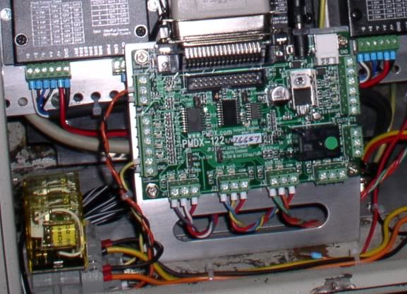
The 5 volt from the Bob is connected to the small relay, (picture above).
The second relay is input from home switches.
-
01-23-2011, 06:26 PM #7
Registered
- Join Date
- Jun 2006
- Posts
- 47
Ok, this is not the best drawing in the world,
Two circuits one E-stop and the other Home, the only data wires involved are just 100 mm long.Last edited by cliffy; 02-16-2016 at 08:49 PM.
-
02-03-2011, 07:03 PM #8
Registered
- Join Date
- Jun 2006
- Posts
- 47
Oh ****, I messed up that post, I’ll have to try again.
Sorry guys
-
07-17-2013, 05:27 AM #9
Registered
- Join Date
- Jan 2011
- Posts
- 14
Thank you, I am one of the lucky ones; as I discovered this before I started wiring.
What you say makes sense and seems to duplicate what real factories use for their robotics.
However, your blueprint isn't as clear as it could be as your data wires are all contained within
a steal panel which shields your data wires.
It is my hopes that I can get my mind around this circuit as my LIMIT sensors are PNP which means
I have rethink your awesome circuit and my LIMIT sensors which provide voltage 10-30 volts when
activated.
Thanks for the thread I have subscribed and I will be back when I get to the wiring.
Edoc

 Reply With Quote
Similar Threads
-
twisted pair shielded or just shielded with whole uniform twist?
By chicof in forum Gecko DrivesReplies: 3Last Post: 10-26-2010, 11:49 PM -
What wires should be shielded?
By eat in forum CNC Machine Related ElectronicsReplies: 8Last Post: 07-23-2007, 05:16 PM -
Shielded versus not shielded cable.....?
By REVCAM_Bob in forum CNC Machine Related ElectronicsReplies: 1Last Post: 05-23-2007, 01:55 PM -
Shielded cable help please.
By Oldmanandhistoy in forum CNC Machine Related ElectronicsReplies: 13Last Post: 04-02-2007, 01:05 PM -
DIY shielded wires
By HogDog in forum CNC Machine Related ElectronicsReplies: 5Last Post: 04-14-2006, 01:02 AM
