


Hey guys,
I'm getting ready to design and build my second cnc router.
The first one ended up being to weak and flimsy.
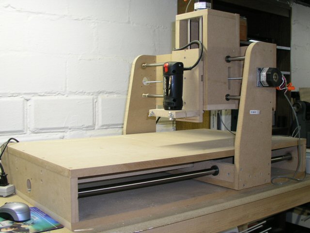
For those of you that are new, here is the first machine...
The 36" bars on the x axis are 3/4", not nearly strong enough. There is way too much deflection... The 24" bars on the y axis are 1/2". Definitely too wimpy. Most of the deflection comes from the Y axis.
So here's the important part. I'm designing a new machine, and I really can't count on the first machine being too accurate. So I want to design a machine that can be built with the least amount of cnc parts, and still have a robust design.
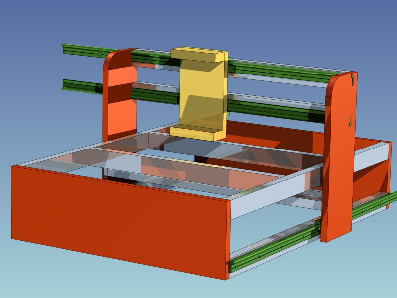
I'll attach a photo of the one that I am starting to design now. Yea, don't mind those slides, I still have to chop them to the right length. Anyways, the silver looking things are 80/20 extruded aluminum. I am using 1x2" extrusions in the design. The red parts are the only parts that I need to cut with my first machine. Probably plywood or MDF. Oh that gold colored thing in the middle? I'll probably buy a z axis from a guy on ebay!!!
The green slides are igus w slides. Based on messages I saw in this forum, it was suggested that I use a single slide on each x axis rather than a double slide on each x axis. But I let my buddy at work look at my design, and he says it needs a double slide on each side. What do you guys think?
Mike...
Results 1 to 20 of 45
-
07-26-2005, 10:59 PM #1
 Registered
- Join Date
- Jan 2004
- Posts
- 236
Is this DIY cnc router robust enough?
-
07-26-2005, 11:20 PM #2
Registered
- Join Date
- May 2003
- Posts
- 550
Couple of points;
The Igus site has a lot of stuff to calculate loading, spacing and alignment. I asked similar questions of Igus tech and got these answers amongst others;
Whatever rail you choose you will need much wider spacing on the bearings on each slide. These rails are not as forgiving as ball slides when it comes to racking miss-alignment.
Single rails should do the X fine from a purely load capacity perspective. Single rails mean you have to mount each bearing individually with the accuracy required.
Double rails would make the cost higher and require much more precise alignment. between rails. A benefit of a double rail each side is that the double rail comes with a mounting plate with the bearings already mounted on the carrage so taking care of some of the precision and probably giving a more ridgid gantry.
These (igus W) bearings have significantly different load capacities in different load directions. Might want to consider that, for example the Y axis might be better with the rails on different planes.
Andrew
-
07-26-2005, 11:38 PM #3
Registered
- Join Date
- Jan 2004
- Posts
- 236
I'm showing 6" in that photo. What width did igus suggest? 8"? 10"? 12"? Originally Posted by fyffe555
My buddy at work was suggesting two single rails on each side. One mounted on the lower extrusion as shown, and one mounted on the upper extrusion. I don't think I have the ability to do something that accurate on my wishy washy cnc router. Originally Posted by fyffe555
My buddy also thought it would rack in a sideways direction. In other words, if you stood in front of the x axis, and grabbed the top of the z axis and pulled it toward you... I don't see how, if the load capacity is there.
So for the y axis you're suggesting a w rail on the top part of the top extrusion, and on the front part of the lower extrusion? What would that gain me? Originally Posted by fyffe555
Mike...
-
07-27-2005, 12:11 AM #4
Registered
- Join Date
- Oct 2004
- Posts
- 590
If those orange parts shown for the y-axis uprights are MDF you definitely want to stiffen them by increasing the section depth to the outside. The 'old machine' suffers from the same problem.
-
07-27-2005, 02:02 AM #5
Registered
- Join Date
- Jan 2004
- Posts
- 236
Please explain "increase section depth" to me... Originally Posted by OCNC
Thanks,
Mike...
-
07-27-2005, 02:12 AM #6
Community Moderator
- Join Date
- Mar 2003
- Posts
- 35538
What he's saying is if you push on the side of the gantry uprights, the 3/4" MDF will flex and the gantry will move from side to side. By at least doubling them up, it will be stiffer. I'm making mine out of 2 pieces of 5/8 MDF, with a 1/2" Hardwood frame in between them. I also epoxied a 3/4" x 3/4" Aluminum tube running from top to bottom, in a rabbit down the center. You want them to resist flexing in all directions.
Not sure how tall the uprights are, but I'd use 2 bearings on the bottom rail, about 12" from outside to outside. A single bearing will probably have binding or sticking issues.Gerry
UCCNC 2017 Screenset
http://www.thecncwoodworker.com/2017.html
Mach3 2010 Screenset
http://www.thecncwoodworker.com/2010.html
JointCAM - CNC Dovetails & Box Joints
http://www.g-forcecnc.com/jointcam.html
(Note: The opinions expressed in this post are my own and are not necessarily those of CNCzone and its management)
-
07-27-2005, 03:24 AM #7
Registered
- Join Date
- May 2003
- Posts
- 550
I suggest you look at the online tools Drylin Expert System. You can work out the dimensions online using the tools there. It varies based on several factors. Basically the distance between bearings on a rail is determined by the leverage (load) produced by the distance between two rails ( racking) and the distance between the bearings and the applied load ( cutting bit and weights and lead screw). The farther between rails or the farther between the cutting bit and any axis rail or the farther between rails and leadscrew increases the loads on the bearings and so increases the bearing spacing. The Igus bearings need to be spaced wider than ball slides because of the different load capacities but the same calculations should be doen for bal slides - they're oftn not because the capacity of the ballslide is usually so large in several directions. From your diagram I'd guess you'd need at least 8-9" on the X slide. More if possible. Depends on the size of router you're putting on there and where the leadscrew is going to go. Originally Posted by mikeschn
I agree with the idea behind the first suggestion because its spreading the load and the top rail would be closer in on plane to the cutting forces. Problem is it would require really close tolerances to install and avoid binding from misalignment. However two seperate rails are no needed since one rail can support the load. Originally Posted by mikeschn
For the second suggestion Ger has it nailed - you need to brace the gantry to avoid movement in twist. trapizoid and flex. Best way is to brace it in several planes. The Bearings are not structural and the bearings cannot be considered to carry any structural load.
Maybe nothing, but if you look at the loads applied while cutting at some point on the table the loads on all the axis are not simple or in just one direction. With bearings that are stronger in one direction than the other you might need to consider how you align the bearings. The Drylin W is roughly half as strong on one direction as the other. Aligning the Y bearings one horizontal and one vertical would mean that in the Y and Z directions the supported loads are the same at 1.5x the max capacity of one rail. If the rails are in the same plane then the load supported is 2x in one direction and 1x in the other. Originally Posted by mikeschn
Again the real reliable info is on the Igus web site an dthe design tools for Drylin W are very useful when planning this stuff.
Andrew
-
07-27-2005, 03:39 AM #8
Gold Member

- Join Date
- Jun 2003
- Posts
- 3312
Have you thought of putting a little extra into the existing router to "beef" it up? For example pull the 3/4" x rails and use them on the Y, and putting larger rails on the X. Or adding bearings on the bottom of the gantry running against a supported drill rod, or a flat piece of crs. There are probably a thousand other methods. While its an after thought, it at least makes this machine much more workable.
PhilPhil, Still too many interests, too many projects, and not enough time!!!!!!!!
Vist my websites - http://pminmo.com & http://millpcbs.com
-
07-27-2005, 03:41 AM #9
Registered
- Join Date
- Feb 2005
- Posts
- 750
What is the cost of these compared to the thomson's or a thk style linear guide? I imagine they are less, but not by much. What I'm getting at is maybe since you are investing heavily in this machine, maybe aluminum would be a better choice for your framing system. Two 80/20 1530 sections and 10 square feet of 1/2" precision plate would not cost much, probably less than 125.00, and eliminate your flexing problems entirely with the same rails and a good design. Then youd have a machine more capabl that would last forever and take much more abuse, or use. Just something to think about.
Halfnutz
(Note: The opinions expressed in this post are my own and are not necessarily those of CNCzone and its management)
-
07-27-2005, 05:04 AM #10
Gold Member
- Join Date
- May 2005
- Posts
- 3920
I think you are about to repeat some of your issues with the previous machine. So I'd rethink the whole formulation.
If you had stiffness problems before I don't see this frame helping alot. But then again I never understood the idea of placing guide rods under table. These should be close to the top of the table. Likewise I don't see alot of y axis support either.
Thanks
Dave
-
07-27-2005, 05:31 AM #11
Member
- Join Date
- Dec 2004
- Posts
- 1316
Your original machine looks well built and only has problems with strength due to the small y-axis rods. I built a JGRO and I used 1.25" seamless shaft (very rigid) with skate bearings on my y-axis. You could use the 0.75" rails presently on your y-axis to strengthen your x-axis. If you improve the original machine it could accurately complete many projects for you.
Jason
-
07-27-2005, 01:17 PM #12
Registered
- Join Date
- Oct 2004
- Posts
- 590
Stiffness increases with the cube of the depth and directly with the elastic modulous of the material. Adding a web is better than doubling up. Aluminum web is better than wood web for the same cross section. The joints between all layers of material must be well glued to each other. Otherwise shear forces will reduce the max stiffness possible with any given composite panel. Originally Posted by ger21
-
07-27-2005, 07:39 PM #13
Registered
- Join Date
- Feb 2005
- Posts
- 168
Dude that is a superb machine and it looks absolutely excellent, I still have yet to start mine as gaining info is critical in getting it right but you're basic design is what I would build EXACTLY!! Why not try and change the existing machine with what you feel needs to and when you know its correct then build youre other based on your improved design, oh and if you want you can send me that machine he,he,he,he. Kammo1
-
07-27-2005, 07:45 PM #14
Community Moderator
- Join Date
- Mar 2003
- Posts
- 35538
Originally Posted by OCNC
My aluminum tube is between the 2 pieces of MDF. Gerry
Gerry
UCCNC 2017 Screenset
http://www.thecncwoodworker.com/2017.html
Mach3 2010 Screenset
http://www.thecncwoodworker.com/2010.html
JointCAM - CNC Dovetails & Box Joints
http://www.g-forcecnc.com/jointcam.html
(Note: The opinions expressed in this post are my own and are not necessarily those of CNCzone and its management)
-
07-28-2005, 03:15 AM #15
Registered
- Join Date
- Oct 2004
- Posts
- 590
Double web wide flange I-beam. Originally Posted by ger21
-
07-28-2005, 09:14 AM #16
Registered
- Join Date
- Oct 2003
- Posts
- 175
your machine follows how mine was made alot i dont have that much flex the big difference i noticed was the width of our gantries mine is set wider at the base so the weight is spred further and causes less flex i do lose a little of my run from it just a thought on a cheap way out till ya can go bigger and better
-
07-28-2005, 12:58 PM #17
Community Moderator
- Join Date
- Mar 2003
- Posts
- 35538
Originally Posted by OCNC
That's it, though it's not rectangular. Much wider at the bottom 12-13" and narrow at the top ~3-4"Gerry
UCCNC 2017 Screenset
http://www.thecncwoodworker.com/2017.html
Mach3 2010 Screenset
http://www.thecncwoodworker.com/2010.html
JointCAM - CNC Dovetails & Box Joints
http://www.g-forcecnc.com/jointcam.html
(Note: The opinions expressed in this post are my own and are not necessarily those of CNCzone and its management)
-
07-28-2005, 03:25 PM #18
Registered
- Join Date
- Jan 2004
- Posts
- 236
Thanks for all the replies...
Here is my second try at a new machine...

You'll note I flipped the bottom extrusion down, and set the w slide on top of it.
I also used a laminated beam on the y axis instead of 2 extrusions. And I put one of the w rails on the top, and the other remained on the lower front.
I doubled the thickness of the gantry sides, and also made the base wider. The base is now 9" wide. I'm going to have to make the table a little longer, as I'd like to have 36" of travel in the x direction.
The z axis is going to be a machined aluminum axis that I buy from ebay, similar to this one...
http://cgi.ebay.com/Z-Axis-CNC-Route...ayphotohosting
The machine now has a lot more wood in it, and it's much heavier too. But I don't figure I'll be moving it much once it's set up.
So did I miss anything?
Mike...
-
07-28-2005, 03:33 PM #19
Community Moderator
- Join Date
- Mar 2003
- Posts
- 35538
I'd consider making the uprights similar to the way I did, using thinner skins, or, drill some large holes to lighten them up a bit. I'd make the Y axis a torsion box. Again, it's lighter and stronger than 2 pieces of MDF. And make sure the bottom 80/20 rails are bolted to a sturdy table that won't allow them to flex.
Do you plan on driving the gantry from a single screw in the center under the table?Gerry
UCCNC 2017 Screenset
http://www.thecncwoodworker.com/2017.html
Mach3 2010 Screenset
http://www.thecncwoodworker.com/2010.html
JointCAM - CNC Dovetails & Box Joints
http://www.g-forcecnc.com/jointcam.html
(Note: The opinions expressed in this post are my own and are not necessarily those of CNCzone and its management)
-
07-28-2005, 03:47 PM #20
Registered
- Join Date
- Jan 2004
- Posts
- 236
I can do that! Originally Posted by ger21
Actually, I was thinking about 3 pieces of plywood laminated together. If I took the inside layer and cut a bunch of holes in it, would that be the same thing as a torsion box? Originally Posted by ger21
Yes, I was thinking about a 1/4-20 threaded rod, like on the first machine. Originally Posted by ger21
Mike...

 Reply With Quote