


Hi readers of the zone,
Been lurking for quite a few years and even started my first build. I May have bitten off more than I could chew trying to build a 1.5tonn cnc router and since settled to build a small mill first. To be honest it was mainly so I could cut the parts I need for the bigger router and nothing to do with how sadly satisfying I find learning about cnc milling
My build so far has taken quite some time as I have spent less than 10 hours behind a very old VMC and maybe half a week behind a manual mill this is all very new.
My progress has been slow because I have little experience/confidence and often worry if I have pulled the right information from around the zone together to result in a well balanced design.
Could more experienced members could look over my design and help weed out any flaws before I commit to sending parts out to be machined would really help me a lot.
I have been given the last warning from my better half about my cnc spending and informed I am to finish something within two months or its all going back on ebay! Sadly it may also have to do with the fact I spend ANY of my spare time working on my cad model and finding new things to worry about/redsign!
So this build post will be about what I have done so far I guess...
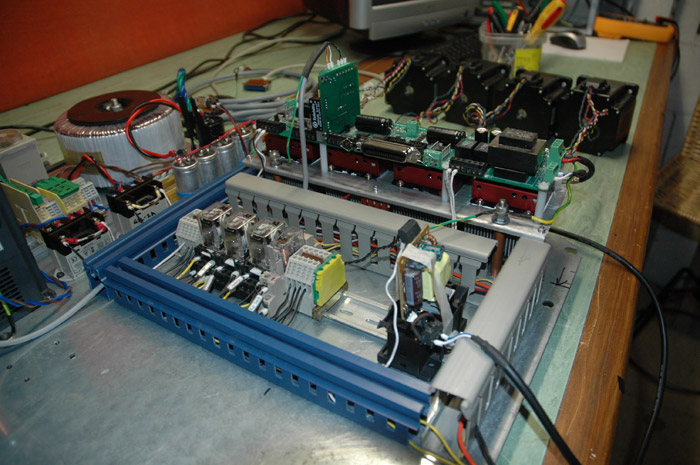
Electronics:
Done and dusted, well apart from drilling a few holes in the enclosure for the buttons and lights...
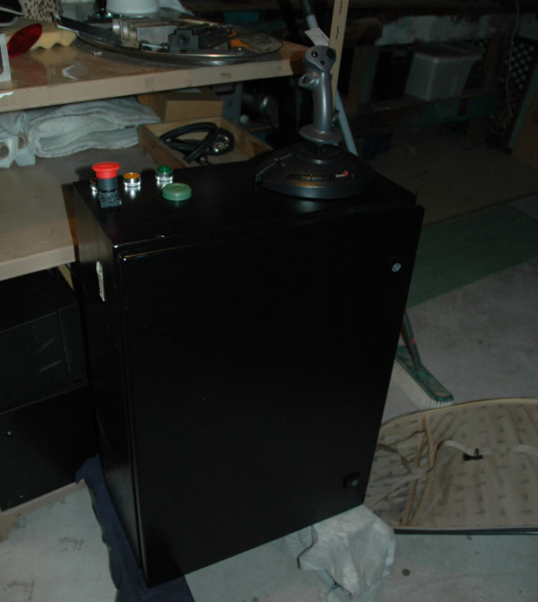
Inside my controller I have:
Pmdx 132 BOB with 4 203v gecko drives underneath
a small bank of 24vdc relays mostly switching low voltage systems
a 24v dc power supply
2-3 relays switching 240v dc
bleed resistor
1 1000va trodial transformer, bridge rectifier and a 18800uf bank of caps (supplying around 65vdc to the drives)
Huanyang VFD
a time delay relay for shorting out the soft start resistor to protect inrush current on the above transformer
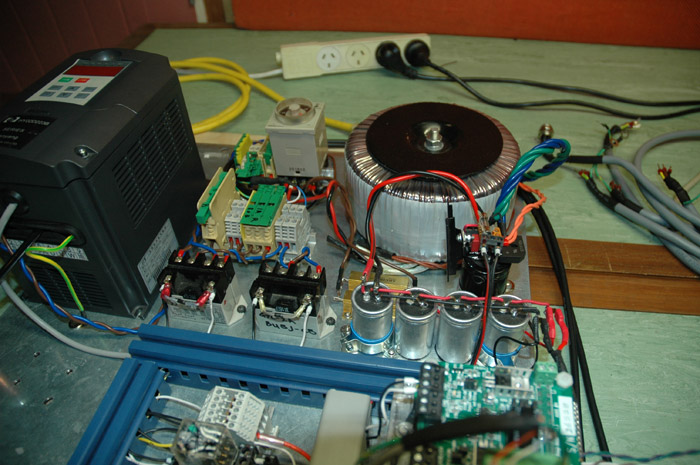
This is actually the controller for my the bigger router but will do until it is needed. At which point this mill will be swapped to servos and a fresh controller. As I want to cut carbon with my router the enclosure will be sealed so I was looking to move as much air around as possible. I have dropped each gecko onto its own cpu cooler that sucks air from the rear over the heatsink and out into the front of the case.

Drive cooler
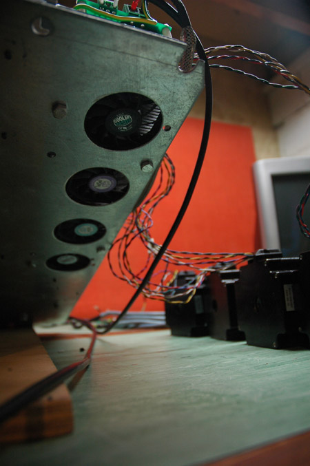
The underside of the riser
The mill:
I had found a good deal on an old mill drill base and table. I was planning on using the table but it was missing its x axis gib strip. I asked around and it turns out cheaper in NZ to import ebay square rails than having a new gib strip made!
So grabbed some 20mm tsubaki rails for the x axis, 25mm nsk rails for the y axis and 25mm sks rails for my z. I have spaced them as wide as possible as It seems that this should really help with the stiffness.
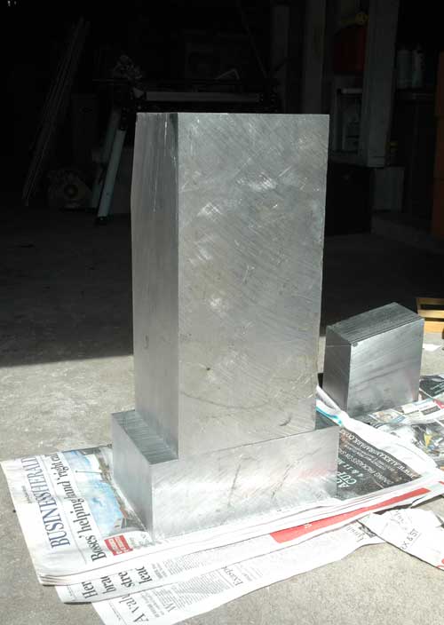
The column is a 70kg solid slab of scrap ally I found for a good price. Maybe a little bit of over kill but heavy can never be bad....
I hope to get my design locked down this week so I can send the mill drill base out to a machine shop to have some webs removed and mounting pads made in the under side of the casting for the end mounts. I would also like to remove the top dove tail and flatten the out side edge of the top of the mill to not only widen my blocks but also increase my z travel.
The table system is still yet to be decided, I am still unsure if a moving table with bigger saddle is a better solution than the standard milling table that is far longer than the saddle.
I would also like to say sorry in advance for poor spell and grammar but I will do my best to make up for it with slightly obsessive determination to see this project actually get finished before my deadline! So please, comments, advice or criticism very welcome.
also not sure of this boards etiquette regarding lots of pictures in posts
thanks in advance
Jestah
Results 1 to 12 of 12
-
06-07-2011, 03:31 PM #1
 Registered
- Join Date
- Jun 2006
- Posts
- 82
 Small desktop mill - New builder, advice appreciated
-
07-11-2011, 06:09 AM #2
Registered
- Join Date
- Mar 2009
- Posts
- 39
Hallo Jestah
I am impressed by the proposals in the drawings.What is the approximate size, weight and travels on each axis? It looks big.Have you made anymore progress?Pictures would be greatly appreciated.
Thats a nice bit of aluminum for the column it must have cost you a bit here in NZ.I would like to build something similar,but my current aspiration is a sherline sized mill using thk hrw35's.
Robert.
-
07-11-2011, 09:59 PM #3
Member
- Join Date
- Apr 2004
- Posts
- 5731
Looks good so far
I'm wondering, though, about the Y-axis. It seems that you're wasting a lot of the travel in your rails. If you shifted the column backwards a bit (and used a longer screw), you'd about double the travel in Y. The X-axis has similar issues - you seem to be trading travel for stability, but I'm not sure you really need 3 sets of trucks - with 2 you'd still have plenty of stability, but considerably more working area.
Think about how you are mounting your work to that table, either with T-slots or a series of threaded holes. And you might also provide a way to move the spindle position up and down, to accomodate higher parts. Did you get a Chinese spindle to go with that VFD? Remember to leave room for bellows, or at least rubber skirts, to protect those rails from that abrasive carbon dust.
Nice job on the controller box. It shouldn't have any problem running a much bigger machine.
Andrew Werby
ComputerSculpture.com — Home Page for Discount Hardware & Software
-
07-12-2011, 05:45 PM #4
Registered
- Join Date
- Jan 2006
- Posts
- 628
Yes, that's a nice looking design. Your electronics box looks first rate and would be instructive for other people designing their controls. It's taken me 3 attempts and it's still not as neat and orderly as yours.
I'm curious if the base will be machined out of another large block of AL, or made of several smaller pieces bolted together. I've been contemplating using large blocks of solid stock, or perhaps granite/epoxy filled 8020 extrusions (to save on milling costs and allow me to do more of the machining).
I like the fact that the Y stepper is hidden away in the base, but will you have to disassemble the mill to get access? Perhaps an access panel on the back (or bottom) would be helpful. Also, if you ever want to convert to brushed servos, they tend to be quite a bit longer with the encoder - and might not fit in that space. AC servos or brushless might do the trick.
Again, these are hypothetical. If you will always stick with steppers, it's probably a non-issue. Looking forward to some build photos. It might inspire me to start on my own mill.
Steve
-
07-23-2011, 12:07 AM #5
Registered
- Join Date
- Jun 2006
- Posts
- 82
Hi guys,
Thanks a ton for the feed back, I can't thank you guys enough for taking some time out to help me along with this project. I often hit a wall with the design (late nights after work trying to focus on at a cad screen is often very unproductive!) so having a few others check out my designs is worth its weight in gold!
This project has change a HUGE amount since first deciding to build a little mill and giving up on my big 8x4 router.
So the past few weeks has been spent adding each bolt, screw and as many details as I could to make sure I could button this little mill together as I have been warned of people placing critical bolts but unable to fit a spanner/hand to tighten them off!
In those drawings it was around 500 deep, 800 wide, 800 tall. The ally is around 70-80kg, base is cast iron and around 25-30kg (I was planning on filling with epoxy/granite) and the saddle and table will be roughly around 50kg Originally Posted by shedbob

The ally was not to bad actually as I found it at a scrap yard and got it for around 9-10 per kg. Its all about hunting as I was lucky to arrive when I did as they were just about to saw it into small parts to help it sell faster!
The Y is placed strangely as I found the base before finding the much longer rails. I had planned on at a later date casting a taller column that would then sit behind the the old mill drill base to give full travel. The ball screw is just long enough to allow full movement along the rails. Originally Posted by awerby
I will ask some questions about the x below as I think you have made some good points.
I was thinking that a 20mm plate that bolts onto the pictured plate with a pattern of m10 threaded holes would work well for work holding. T slots looks a little scary for my first ally milling project..... I also like the idea of having other table that could be swapped in and out for other tasks (small vac table or bolt on rotary 4th axis ). I was thinking of having a moving spindle height but fell that increasing the size of the stand off for more rigidity over a far longer reach is more critical in my new design below.
I did get a 2.2kw water cooled one with the vdf, had it running smoothly on the test bench, get to cut any thing! As far as I can tell it should be a good starting spindle until I can justify looking for something with a faster manual tool change.
I have been looking but cant find a nz stockiest of bellows. Any good online sources that you would recommend? My y+ axis is the only point where space is an issue, would 50mm compressed bellows extend out to 270mm? This is the space I have accounted for but able to work more or less. I have also been looking at a more ridged sliding plate idea the past week using some folded thin aluminium sheet. Give it some angles and draft to help encourage swaf off and away from the mill. I am concerned on the y travel towards the column can trap lots of debris.
Hi Steve, Originally Posted by stevespo
I can not take to much credit for the control box. Henrik posted some really good info on this post :http://www.cnczone.com/forums/diy-cn..._question.html He was also kind enough to really help a few members really understand how it worked and how to do some basic configuration for most uses. The next tip I can give any builders out there is hunt at scrap yards that decommission old factories. MOST of that controller ( apart from bob, drivers, vdf, psu) was from a scrap yard and cost very little. Lastly if you want a clean controller it is very much worth getting a few spools of good quality coloured wire, an automatic wire stripper and boot lace ends with the crimp tool. Once you have your wire ends crimped you get a far better connection but more importantly swapping wires/trouble shooting/ re wiring becomes far smoother as you have something to grip and less change of a stray wire shorting your system.
The base : started life as a mill drill base, then was getting key surfaces remachined and finally back filled with E/G. I have since decided that I am just going to leap both feet first and scrap the base and cast a solid E/G base!!! I would say that you should keep up with your idea of casting into extrusion, If we could buy it cheaply in NZ that would be the option I would take.
With the new cast base I will have an open back for the y motor so can convert to servos when this controller is moved on to it final home (larger wood router). I was wondering if all servo systems should be geared or can a direct drive servo system still be efficient?
SOOOOOooooo long story short, I was waiting on a machinist to finish cutting some flat surfaces on my mill drill base for mounts, rails etc and after 3 weeks of being over due I decided its a sign to just scrap the little undersized base and cast the sucker from scratch!!!
The whole design has changed and I am now in the process of updating my drawings but here is the rough mock up so far:
At the moment I have two options 400x380x350(z) cutting envelope but feel that then I have a very long span to step the spindle out to the mid point between the rails (plus the 50mm of bellows clearance) around 320mm or 12.5" with such a narrow spread of the mounting blocks of the bearing cars (the red block is 260*120 (10x4.7").
My second option and the one pictured above would be to swap the shorter z rails down onto the y axis giving a working size of 400x270x400z. With this lay out I would have to split the cast base into two and scrap the ally blocks to cast a taller (and possibly wider) column. I could also spread the blocks a bit wider and taller as well as having a far shorter reach for the spindle clamp.
Both options will required my bolt on clamping table to be 100mm wider than the bearing block spacing which makes me wonder if this could place a moment loading on the blocks and if it would be a better design to widen the spacing at the cost of cutting area.
With the first option I also have to overhang the table and cant help but feel this is not the best for stiffness. I am very new to working with metals (give me carbon and epoxy any day!) so also very open to being told that I am just being far to conservative. Could someone help me understand the bearing data sheets as I do have a feeing that the blocks may just be stiff enough.
Once again, thanks for looking and commenting, keep it coming as it is really helping me along! Once I have locked in which lay out I will be using I hope this weekend to then draw up a casting mould, cutting that next week and have lined up casting at a granite counter top factory the following week!
While the first option is tempting for cutting real-estate I do not like the look of having a over sized table
-
07-23-2011, 01:51 PM #6
Registered
- Join Date
- Nov 2008
- Posts
- 16
Planning looks great ,waiting to see the finish.
nice Good luck
-
07-23-2011, 02:26 PM #7
Registered
- Join Date
- Apr 2009
- Posts
- 43
There are a bunch of these CAD-CAM drawing projects already on this board. They are nothing more than an exercise in talking about some fantasy. Just buy yourself a ready made small mill and hook up your CNC or take your wife's advice. Originally Posted by jestah
-
07-23-2011, 03:18 PM #8
Registered
- Join Date
- Jan 2006
- Posts
- 628
I can't be much help with your design questions, other than to say I might enlarge the spindle mounting arm and increase the height of the (red) mounting plate to space out the bearings a bit more and help with the torque on the spindle arm. Given that you'll be using fairly small sized tools with the 2.2kW spindle, maybe that isn't really an issue.
As far as servos go - like anything else they need to be matched to the application. They can absolutely be direct driven because they have very consistent torque over the RPM range. I direct drive on my wood router with 300W BLDC servos. Because servos tend to have a wide RPM range, people often gear them down to increase the mechanical advantage and use as much of that RPM range as possible.
What type of screws are you planning to use?
Steve
-
07-23-2011, 10:01 PM #9
Registered
- Join Date
- Jun 2006
- Posts
- 82
wow man, thanks for the encouragement! buying a ready made mill is not an option as I want to build it so I can fix it when it brakes down! Originally Posted by digitalmdi
I have started but have struggled to confirm that my design is based on some good principles and that I have accounted for all of the major stresses/factors.
I had planned on beefing up that spindle mount, this was one of the last parts to be cut so had left the design until the casting of the base was well under way. I also planned to run more fast feeds with smaller cutters so was also feeling the same as you (little need for HUGE stiffness to combat HUGE cutters). I think i will also lean to swapping to the second design with smaller cutting space but far better spacing and to the eye a more balanced layout. I can't help but feel a cutting spaced longer than the spacing of the bearings will create points of flex or areas where leverage could affect my accuracy. Originally Posted by stevespo
Thanks for the info on the servos. I think I will play it safe and work in space to both direct drive or gear with a tooth pully and belt to give me options when i get to that upgrade.
I plan on using ballscrews from Linearmotion2008 on ebay. I have a stack of end mounts for 16mm screws so now just deciding between 5 or 10mm pitch
once again, thanks for all the feed back guys! Keep it coming!
-
07-26-2011, 06:26 PM #10
Registered
- Join Date
- Apr 2009
- Posts
- 43
[QUOTE=jestah;969609]wow man, thanks for the encouragement! buying a ready made mill is not an option as I want to build it so I can fix it when it brakes down!
Sorry to throw water on your fire, but as one who has "been there-done that" I can predict that at the very best, it will take you 6 months and many $ before you even make your first test cut. Then an equal amount of time refining it to a working unit. You could buy a Chinese mill, tear it down and re-assemble it the right way in a few weeks. Or just buy a Tormach and go to work. If this is just a hobby project to see if you can build something, then the time and $ are no problem.
-
07-26-2011, 10:31 PM #11
Registered
- Join Date
- Jun 2006
- Posts
- 82
[quote=digitalmdi;970599]
I have been well over 6 months, threeish years to date but have been given very clear end point. I am to far invested in the parts/stock i have and to be honest that is about 99% of the things I will need to finish the project. Originally Posted by jestah
I have just got back from the company I plan to use to cast my base and possibly column from epoxy. I just now have to double check with my resin guys if the rubber tuffened resin system I use will be ok in such a big mix (around 15-20L will be needed) and make a mould at work and I'm ready to cast.
Once the base is done I have an other cnc builder who is willing to then cut all the required mounting surfaces and do all the drilling and tapping.
The electronics are done and ready to be mounted so really starting to feel things are coming together well!
Don't worry about your comment, Think of it more like tossing water onto a boiling pot of oil! Gave me a nudge to prove you wrong!
sorry there are not much photos yet guys, will make sure to take some when I am making the mould and while i am casting the base.
Big question now is my 6z rails. Could some one help me understand the bearing load rating chart and the numbers I can use to decide on my final spacing? I have a final reach of around 400mm and plan to use a small high speed spindle cutting small cuts fast in ally and hopefully some work in steel. I know in the drawing the stand off looks a little small but that is just a mock up to get spacing correct. I would like to now work on working out exact bearing spacing and stand off size to lock in the design .
thanks
jestah
-
07-27-2011, 02:43 PM #12
Registered
- Join Date
- Apr 2009
- Posts
- 43
[quote=jestah;970675]
Maybe I misread your post- I thought it was another of those Cad-Cam fantasies where they drone on for months and years with endless calculations about the distance to the moon divided by the square root of the universe. Looks like you are well into the project, with a definite plan in mind. Would like to see more pictures as you progress- the guy who built the slant bed lathe has a really good thread. Originally Posted by digitalmdi
Good luck

 Reply With Quote
Similar Threads
-
Need Advice on a Desktop Mill
By LatheMaster in forum Benchtop MachinesReplies: 7Last Post: 11-15-2010, 08:33 PM -
Getting Ready for Mill Delivery - Advice Appreciated
By webgeek in forum NovakonReplies: 4Last Post: 08-19-2010, 09:04 PM -
Considering a (first) machine build, a small desktop mill
By footloose in forum Open Source CNC Machine DesignsReplies: 6Last Post: 05-25-2010, 07:12 AM -
Small desktop gen-purpose CNC mill on a shoestring budget
By GreenLead in forum Benchtop MachinesReplies: 33Last Post: 09-15-2008, 03:03 AM
