


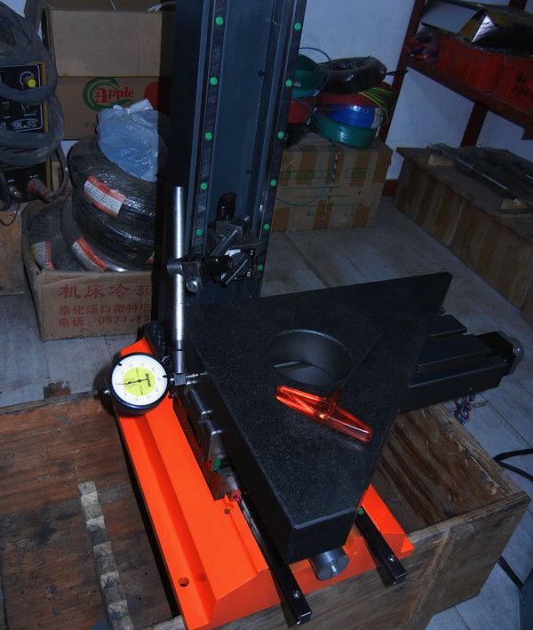
seems working now.
cleaning the machine body and install the blocks again:
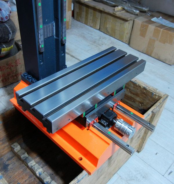
re-install the worktable and saddle module:
recover the accuracy again:
Results 161 to 180 of 3662
-
03-08-2013, 07:07 AM #161
 Registered

- Join Date
- Jul 2011
- Posts
- 441
www.skyfirecnc.com
Email: [email protected]; Skype: skyfirecnc
-
03-08-2013, 04:48 PM #162
Gold Member
- Join Date
- Jul 2007
- Posts
- 1602
Have you thought of pocketing the saddle where the X and Y blocks are? That would bring the table closer to the base and would probably improve rigidity.
bob
-
03-09-2013, 02:33 AM #163
Member
- Join Date
- Sep 2006
- Posts
- 6463
Hi Skyfire, is it necessary to have the electronics box attached to the machine body instead of off the machine?
Then you can have a decent sized box for the electronics without having to squeeze everything into a tiny space which also allows a decent sized cooling fan.
The computer and display are off machine, and the computer only needs to operate the machine without having to do computing functions....usually the computer is an older one running Win XP, which makes it a big box for a simple function.......for some reason laptop computers are not suitable for CNC use, but as they are very compact and have a display and keyboard built in, would be very practical.
Is it that laptops do not have the connectivity a PC has?
Ian.
-
03-09-2013, 03:25 PM #164
Registered
- Join Date
- Jul 2011
- Posts
- 441
Hi rowbare. I understand what you mean of pocketing the saddle and fit in the linear blocks to lower the wortable and certainly it will help to make the structure more stable. But actually the saddle don't have the space to allow this. It may seems very thick from the front side but actually it has a big groove inside to mount the ballscrew. And if I pocketing the saddle even without this groove, it will need the linear blocks indent into the saddle and this will cause the rigidity worse bacuse the arm of force will be short. So.. compared with the total hight of the worktable, this is a bigger concern here. So, believe me the saddle has been the lowest considering together enough thickness, low hight and biggest force arm issue, and ballscrew mount issue. Originally Posted by rowbare
 www.skyfirecnc.com
Email: [email protected]; Skype: skyfirecnc
-
03-09-2013, 04:02 PM #165
Registered
- Join Date
- Jul 2011
- Posts
- 441
Hi buddy. Yes, I think the electric box attached to the machine body is my best choice because: Originally Posted by handlewanker
1. compact shipping size. I realized this because you guys have brought out this issue as a big challange. I have thought about the electric box seperated but the totall package will be much bigger.
2. most reliable electric connections. if using a seperated elctric box, I have to place many connectors including every motor drive lines, especially high voltage spindle drive lines; and many signal connectors. this will cause much complex wire works and potential problems. also this will caused much higher cost.
3. I really like to make wires as short as possible to reduce EMI. poor EMI will cause headache problem and even you can't find where the problem is.
4. yes. usually we use a standard PC to control the CNC, so I really don't want another big box beside the PC case. ..
Yes. the laptops sometimes are not fitful to run the CNC software especially when we use the parallel port. One of the reason is that the laptop usually has the auto-underclocking functon and may cause the pulse output unstable. and another issue is that the pulse output voltage of the laptop is 3.3V, not 5V as the PC has. So this is some potential problem also. especiall if the breakout boards don't have the buffer chips to convert the 3.3V to 5V, or don't have photocouplers to make the signal very clean. There may have some other reasons that the laptop are not best choice.. but some very old type laptop may don't have the problems. And if working with the MODBUS controllers, it's totally no problem because the controller will do the pulse engine job.www.skyfirecnc.com
Email: [email protected]; Skype: skyfirecnc
-
03-10-2013, 12:20 AM #166
Registered
- Join Date
- Oct 2005
- Posts
- 375
Very nice machine, what kind of spindle are you going to use?
Do you have pictures of it.
-
03-10-2013, 05:02 PM #167
Registered
- Join Date
- Jul 2011
- Posts
- 441
Hi, I plan to build a spindle by my own design. It will be a spindle with two groups of angle contact bearings so totally 4 bearings. It will have a ER25 taper. The spindle parts are under machining so I will show several days later. Welcome any other comments!~ Originally Posted by veteq
www.skyfirecnc.com
Email: [email protected]; Skype: skyfirecnc
-
03-11-2013, 03:08 PM #168
Registered
- Join Date
- Jul 2011
- Posts
- 441
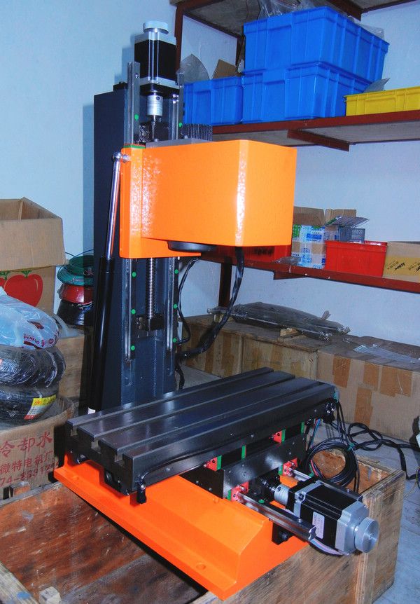
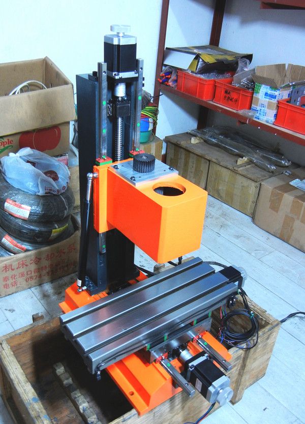
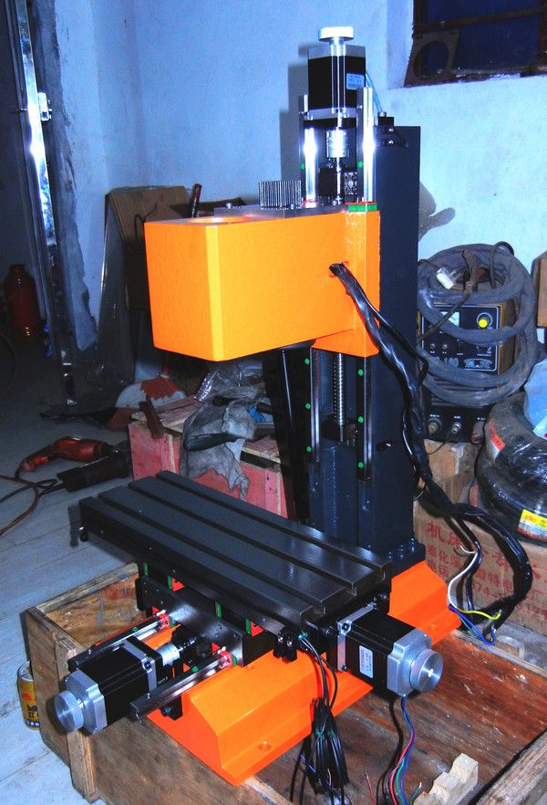
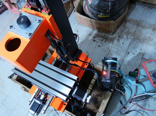
installed head part and motors. and some wireworks done.
 www.skyfirecnc.com
Email: [email protected]; Skype: skyfirecnc
-
03-12-2013, 08:18 AM #169
Registered
- Join Date
- Jul 2011
- Posts
- 11
Looking good! I really dig the colour scheme you have chosen. So is the spindle motor inside the head then? Nice tidy design. Can't wait to see the spindle.
-
03-12-2013, 12:58 PM #170
Plastic
- Join Date
- Mar 2013
- Posts
- 0
Much more dedicated than the off the shelf parts I used.

-
03-12-2013, 03:38 PM #171
Registered
- Join Date
- Jul 2011
- Posts
- 441
Hi Dubbie99. Thank you. Yes the spindle motor is put inside the head box. The spindle unit part may be received in 2-3days. so I can show it and installed to the head then Originally Posted by Dubbie99
 www.skyfirecnc.com
Email: [email protected]; Skype: skyfirecnc
-
03-12-2013, 04:20 PM #172
Member
- Join Date
- Sep 2005
- Posts
- 1195
Did you make your own spindle or you just bought one? Thanks.
-
03-13-2013, 02:37 AM #173
Registered
- Join Date
- Jul 2011
- Posts
- 441
Hi asuratman, the spindle is my own design and the parts are made on my machining side because I don't have a lathe. I have the bearings, pulley in hand now, and need to receive the other parts to assemble by myself. Originally Posted by asuratman
www.skyfirecnc.com
Email: [email protected]; Skype: skyfirecnc
-
03-23-2013, 05:18 PM #174
Registered
- Join Date
- Jul 2011
- Posts
- 441
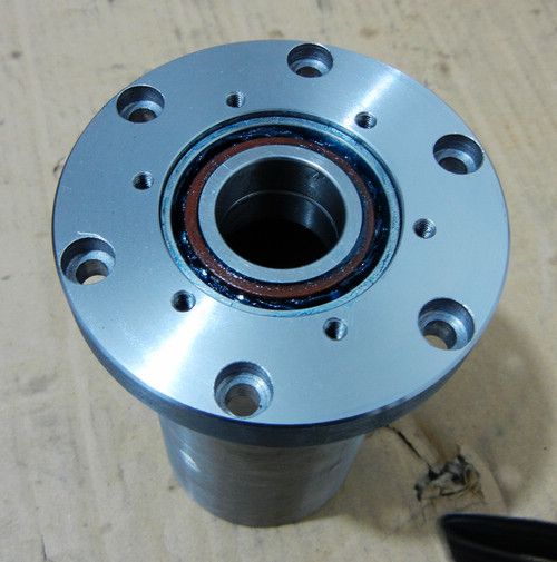
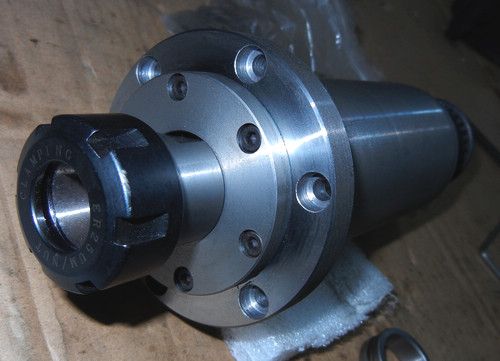
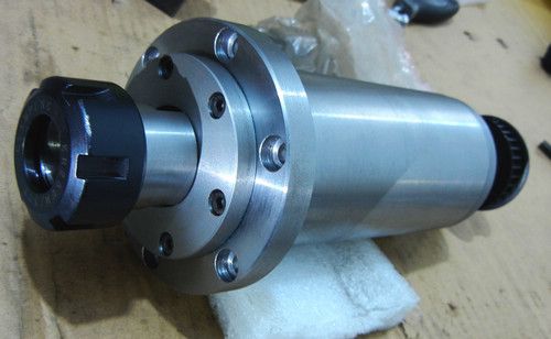
Hi guys, I've left for a small trip recently so have not updated for days. I have received the spindle parts and tried to assemble one. Here I post some pictures of the spindle unit now. But I have made a small mistake on the sketch of the end cover diameter. So I couldn't full assmebled the spindle yet. but can just used for picture now
I will correct the small DIA. mistake by lathe again. it will be a small work. Other things should be no problem. .. bearings and axit shaft are just fit in well.
I will take more pictures when the spindle completed installed.
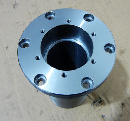
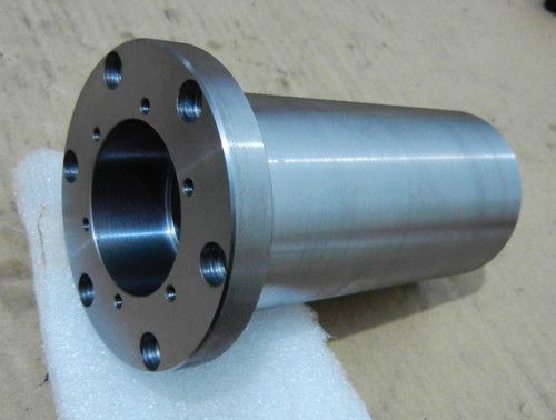
fit in the bearings:
 www.skyfirecnc.com
Email: [email protected]; Skype: skyfirecnc
-
03-23-2013, 06:07 PM #175
Member
- Join Date
- Sep 2006
- Posts
- 6463
Ah Ha, good thinking Batman....ER collet chuck directly in the spindle end, so no drawbar problems.
What collet size is that?
If it is ER32 you could fit all 3/4" parallel shank tooling like Tormach stuff or plain shank cheaper ones.
If the sale mills are as good a quality as the turning on the spindle assy, they'll sell like hot cakes.....if the price is right...LOL.
I'd have to say that with your suggested approximate price, who would want to buy a ready made manual mill and convert it to CNC when this one is already a fully CNC'd machine with the very desirable Linear slides, ER spindle and ball screws......right out of the box.
BTW, what method of sealing and lubrication are you using at the bottom end.....I assume the top end has a sealed radial ball race
This has been an amazing build.
Ian.
-
03-23-2013, 06:29 PM #176
Registered
- Join Date
- Jul 2011
- Posts
- 441
Hi Ian. nice to meet you again. The collet is ER25 type for this sample one. of course it could be ER32, or even ER40. I can go with ER32 if this is some better choice. Originally Posted by handlewanker
Thank you for your possible maket estimate.. This really give me much confidance to bring the benchtop machines to the market recently.
I'm begining to build the enclosure and electric box now. and some electric tests also. I will be able to keep update the process frequently from now again.
cheers~~www.skyfirecnc.com
Email: [email protected]; Skype: skyfirecnc
-
03-24-2013, 05:00 AM #177
S.N.A.F.U.

- Join Date
- Jan 2005
- Posts
- 1880
er collets are awesome and accurate but if you can't get a draw-bar or some such device then you can never have an automatic tool changer or even a fast tool change. Just something to think about.
thanks
Michael T.
"If you don't stand for something, chances are, you'll fall for anything!"
-
03-25-2013, 03:28 AM #178
Registered
- Join Date
- Jul 2011
- Posts
- 441
Hi miljnor. Thank you for inputs~ Yes, the spindle unit didn't consdier the ATC issue. My aim is to make it as accurate as possible and I don't think the ATC is quite necessory for most users unless you will use it for high efficient batch machining products. If some guy does have such deminds, I will say the electric spindle supporting ATC function will be some best choice for this purpose. Originally Posted by miljnor
www.skyfirecnc.com
Email: [email protected]; Skype: skyfirecnc
-
03-25-2013, 03:53 AM #179
Registered
- Join Date
- Jul 2011
- Posts
- 441
I have just drive up the spindle motor today by manual speed control. I used the BLDC driver sample as I mentioned and kept it running at 3000RPM for 3 hours. the motor response well and seems run smooth without any problem for the idle test. This is just some initial tests to make sure I can go forward. I have also taken a video of the motor running and will see if have some way to show here.
 www.skyfirecnc.com
Email: [email protected]; Skype: skyfirecnc
-
03-25-2013, 07:32 PM #180
Member
- Join Date
- Sep 2006
- Posts
- 6463
Hi, It's looking so good now.....I quite agree with the simplicity of the ER collet spindle for the person who wants CNC without the need for a production item, but although it has great accuracy it is a cumbersome method to change tooling when just a small batch quantity is being undertaken.
It is a PITA to have to loosen the ER collet nut (double spanners or spindle brake) each time you want to make a tool change, IE, when you have multi same operations on each item that requires you to first mill the area then centre drill, drill a number of holes for tapping, counter bore the hole and chamfer it with tapping as the final operation, each requiring a tool change to do just a simple set of ops.....6 tools in all.
I realise that it would be quicker to do each operation for all milling and holes etc under CNC control, using each tool in sequence for all the ops and then changing to the next tool and doing all the ops in it's range etc, as opposed to changing the tool for each hole etc as you would do in a manual mill.....(just gotta think CNC and forget manual methods).
Which leads on to the ER collet nut clamping......it's a PITA to have to remove it and dismount the collet each time you want to change operations, (seperate nut/collet/tool assembly?) especially as you need to work the spanner and remove the nut with the right hand, (spindle must be braked for this operation, remembering to release the brake before switching the spindle motor on) while holding the tool with the left hand and remounting a new tool to the nut and insert to the spindle and do up the nut etc.
I think in this situation an ER spindle with a 3/4"or 20mm collet in the chuck all the time so that the parallel shank tooling would come into it's own with the need to only loosen the ER collet nut and remove the complete parallel shank tool holder as an assembly for it's particular function, provided there was some method to locate the tool shank positively inside the spindle probably by a stop on the tool holder end.
In this situation, where manual tool changing is the mode, I would like to see perhaps a 3/4" or 20mm R8 collet with power draw bar so that you could just press a button to have the collet release the tool and manually retrieve it and replace with the next tool, no ATC complication necessary, but could be added as an option if required once the tool change method is established.
It is possible that a "special" ER collet with 3/4" or 20mm bore could be used with a power draw bar, and dispense with the ER collet closer nut.......the collet in the ER system locates and clamps the tool in the holder body with the taper on the collet body, the taper at the top just presses the collet back into the chuck and also acts as an extraction and removal method for the collet.
This is similar to the R8 collet clamping system, but without the long body of the R8 closer.
All it needs is the spindle to be bored through for a draw bar, a spring loaded clamping system, a pneumatic/electric solenoid to activate the collet release and a special draw bar with ER collet end............but it would most probably be simpler to fit a Tormach R8 type collet closer system if that is anticipated and have the Tormach tooling system available or just parallel shank tooling for economy.
Ian.

Similar Threads
-
Show us your machine stands
By OHLEMANNR in forum Benchtop MachinesReplies: 7Last Post: 05-05-2013, 03:19 AM -
a machine design (pics) from beginning to end
By blurrycustoms in forum Vertical Mill, Lathe Project LogReplies: 42Last Post: 04-25-2013, 02:36 AM -
dry build or glue from the beginning?
By Ezra in forum Joes CNC Model 2006Replies: 2Last Post: 10-29-2010, 04:44 AM -
Newcastle: Beginning of build plan
By pippin88 in forum Australia, New Zealand Club HouseReplies: 7Last Post: 09-16-2010, 10:22 AM -
Beginning to build my Z-axis.
By zonk2 in forum DIY CNC Router Table MachinesReplies: 0Last Post: 12-23-2008, 06:17 AM
