


I have the program set up to cut where I want. I have set 0,0 to be the lower left hand corner of the work.
How can I zero out the machine so 0,0 is at the lower left hand corner of the machine? I have tried using an edge finder but I can't seem to get it exactly right. I need a really accurate way of doing this.
Here is a drawing

Results 1 to 9 of 9
-
08-28-2011, 05:48 PM #1
 Registered
- Join Date
- Feb 2011
- Posts
- 0
 Accurate way to "zero" work inside a vise?
-
08-28-2011, 08:27 PM #2
Registered
- Join Date
- Jun 2007
- Posts
- 143
Some skill is required. Don't be discouraged that the center finder didn't instantly tell you where the edges are. Go play with it some more. Good skills do not instantly happen. It might take 10 to 15 minutes to locate the edges until you get the hang of it. Here is a link from the Tormach site that might help; <http://www.youtube.com/watch?v=f0od-cp_9dg&feature=youtube_gdata>
You can always throw money at this problem and buy one of these: <probe cnc,cmm | eBay.
Your option.
-
08-28-2011, 08:37 PM #3
Registered
- Join Date
- Feb 2011
- Posts
- 0
I watched the Tormach video already, but probably didn't calculate the offsets correctly. Is it good practice to find center off the front and side of the vise like I've been doing?
I'll try it again and see if I can get closer.
 Originally Posted by flyinchips

-
08-28-2011, 09:03 PM #4
Member
- Join Date
- Aug 2009
- Posts
- 684
Best practice is to come off the fixed jaw for multiple parts. A suitable DTI is my preferred choice for accurate edge-finding.
DP
-
08-28-2011, 09:18 PM #5
Registered
- Join Date
- Feb 2011
- Posts
- 0
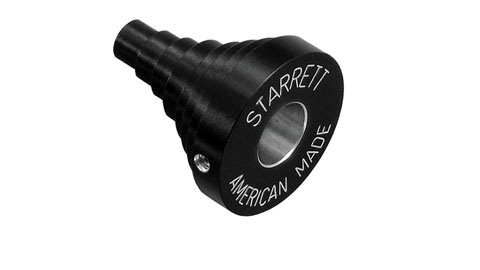
DTI? What is that? The edge finder I have is the standard, non-digital type that has a spring loaded mechanism that will "snap" when the probe reaches the edge.
Looks like this:
Originally Posted by christinandavid
-
08-28-2011, 09:21 PM #6
Member
- Join Date
- Aug 2009
- Posts
- 684
Browse the UK Master Catalog
This style of DTI is extremely versatile.
DP
The edge-finder I used always claimed that the 'light-line' technique (ie bring the edgefinder to the part until you see no light between them) was more accurate than the 'run-off' point for finding an edge. In the end I found both methods to be crap . Depends how good you need it to be I suppose...how much error are we talking about?
DP
-
08-29-2011, 12:01 PM #7
Member
- Join Date
- Feb 2008
- Posts
- 521
Can you explain the technique as I can figure using the DTI for finding an edge but not centring the spindle with it? How are you determining the DTI offset from spindle c/line? or is it similar to a co-axial indicator? Originally Posted by christinandavid
-
08-29-2011, 12:43 PM #8
Registered
- Join Date
- Feb 2011
- Posts
- 0
Here is a good video that explains a couple different techniques.
[ame=http://www.youtube.com/watch?v=r7-eEj_qq5M&feature=related]Crash Course in Milling: Chapter 5 - Work Locating, by Glacern Machine Tools - YouTube[/ame]
Originally Posted by kawazuki
-
08-29-2011, 01:08 PM #9
Member
- Join Date
- Aug 2009
- Posts
- 684
The DTI can be used exactly like a coaxial indicator. The DTI offset can be found by clocking a feature of known size. If you only have an edge to go off, clock the edge and set zero. Place a parallel block against the edge and clock it the same - voila, you have found the position of the edge and the offset of your DTI. Originally Posted by kawazuki
DP
Warning, DTIs and multiple rapid moves don't mix....

 Reply With Quote
Similar Threads
-
inside arcs with comp doing "loop de loops"
By Mikey69 in forum FanucReplies: 11Last Post: 06-01-2009, 03:13 PM -
"Inexpensive" vise recommendations?
By touser in forum MetalWork DiscussionReplies: 12Last Post: 03-13-2008, 07:31 PM -
Home Made Vise Stop - For 6" Kurt Vise
By widgitmaster in forum Bridgeport / Hardinge MillsReplies: 20Last Post: 12-15-2006, 03:49 PM -
3D image "cracked" inside glass
By moyesboy2 in forum Glass, Plastic and StoneReplies: 17Last Post: 08-04-2006, 07:42 AM -
cheap DIY low profile "softjaws" vise for TAIG
By Smertrios in forum Taig Mills / LathesReplies: 3Last Post: 04-29-2006, 06:20 AM
