


I started my CNC adventure last March with an off-the-shelf CNC Shark Pro+ (from Nextwaveautomation/Rockler) and learned a lot. But I found quickly that this machine (while fun for light duty woodworking and carving) did not fit the bill for precise mechanical prototyping in plastic and aluminum due to lack of rigidity and control software features.
So, I decided to build my own machine with the focus on rigidity, also a bit bigger. The intent was to use the Shark Pro+ to cut the critical components of the new machine and to sell it when finished as to recover most of the cost.
Now, I started buying some stuff before I ran into this forum, so some may be sub-optimal (i.e. overkill) as I learned but at least I got some good design advice from Ger21 and others.
The design is as in the picture below, with a 36" x 31" x 8" motion range, 80/20 T-slot table and all structural parts made from 3-ply 3/4" Bamboo plywood. I mentioned that in another thread and there was some doubt about the suitability of bamboo but i did a lot of research and found it:
- has the same weight/stiffness ratio as aluminum (slightly more than Birch). The lower absolute modulus does however require larger cross-sections compared to aluminum.
- it is unfortunately also a bit more expensive than Birch
- is very nice to machine precisely without much fuzz
- is very hard, i.e. metal parts bolted to it won't sink in easily
- well, it also looks interesting..... and I can get high quality flat sheets locally
I just started the build. More info in following posts.

Results 1 to 20 of 647
Hybrid View
-
08-29-2011, 12:12 AM #1
 Registered
- Join Date
- Aug 2011
- Posts
- 999
Big Bamboo - New Machine Project Started
-
08-29-2011, 12:22 AM #2
Registered
- Join Date
- Aug 2011
- Posts
- 999
Here some pictures of my first build activities....
Table prepared with mounting holes for 80/20 profiles (type 1545)

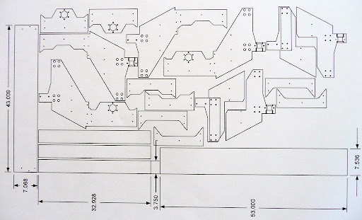
Started cutting parts:

How to make most of an 8x4' sheet:
Cart is ready (made from 2x4 lumber) and preparing the stringers for the table:

Bolting the rails to the 8/20 profiles:

Bearing mount for x-axis thrust bearings (double tapered roller bearings):

-
08-29-2011, 12:35 AM #3
Registered
- Join Date
- Aug 2011
- Posts
- 999
As I learned the NEMA34 steppers that I bought are seriously oversize for this kind of machine (1600 in-oz) but I decided to keep them anyway. I will run them a bit under nominal current and they will surely not overheat....
Another advantage is the massive 14mm motor shaft with substantial bearings which should allow me to run the z-axis without separate thrust bearings (I hope). Both x-axis steppers will be force-synchronized with a timing belt.
All lead screws are surplus Kuroda ground ballscrews 15mm dia x 15mm pitch.
Otherwise: 20mm supported rails mounted in opposing direction; the lower rail of the y-axis and the lower end of the z-axis will have 4 instead of 2 trucks to help with the higher forces.
The z-axis has the trucks fixed and the rails moving. Just came out easier that way.
-
08-29-2011, 02:13 PM #4
Registered
- Join Date
- Aug 2011
- Posts
- 0
how accurate is the setup with two x screws and a belt drive?
can it lead to racking?
-
08-29-2011, 04:22 PM #5
Registered
- Join Date
- Aug 2011
- Posts
- 999
Obviously I don't know yet ;-) Originally Posted by technodream

But the intent is in normal operation for the belt to pretty much idle along, that means I will not give it much tension and hope it will not have much detent effect (if that is what you mean with racking).
The purpose is more as a safety device in case of electrical malfunction. The worst case would be that one drive loses the pulse and is held firmly in place while the other one wants to go ahead full torque. In this case I suspect serious gantry damage that could be avoided with the belt. But maybe I am just paranoid and in a way, the belt is optional.
-
08-30-2011, 06:16 AM #6
Gold Member
- Join Date
- Apr 2009
- Posts
- 5516
Since you have these powerful steppers, have you considered just running one stepper for the x axis, sing the belt to drive the two screws? Originally Posted by JerryBurks
Cool looking bamboo panels!
-
08-29-2011, 03:20 PM #7
Community Moderator
- Join Date
- Mar 2003
- Posts
- 35538
If you can somehow add a panel to close in the gantry, it could then be a torsion box, and would be much stronger. With the spindle in the center of the gantry, the gantry looks like it might be susceptible to twisting.
Gerry
UCCNC 2017 Screenset
http://www.thecncwoodworker.com/2017.html
Mach3 2010 Screenset
http://www.thecncwoodworker.com/2010.html
JointCAM - CNC Dovetails & Box Joints
http://www.g-forcecnc.com/jointcam.html
(Note: The opinions expressed in this post are my own and are not necessarily those of CNCzone and its management)
-
08-29-2011, 04:38 PM #8
Registered
- Join Date
- Aug 2011
- Posts
- 999
Thanks for the hint, I am probably going to do that. Originally Posted by ger21
-
08-29-2011, 08:24 PM #9
Registered
- Join Date
- Jan 2006
- Posts
- 628
Jerry,
It's great to see someone trying out a new material.
Although the NEMA 34 bearings might handle heavy radial loads, I'd be very tempted incorporate a thrust bearing to handle the axial loads on the Z.
Also, I'm trying to understand the timing belt. Just thinking out loud here.
If one motor misses a step (or thirty), it seems unlikely the other motor will be able to "right" the system. A moving motor will always have less torque than a stopped motor, so it should never win that battle.
In that case, maybe what happens is that the active motor being unable to budge the stopped motor will also lose steps and the two become synchronized again, but the error is not mechanically corrected. The job is probably ruined, but perhaps no damage to the machine has occurred. (Maybe my thinking is wrong about this.)
Anyway, since you've got those honking motors, why not drive both screws with a single motor and use the timing belt to prevent racking due to lost steps?
Steve
-
08-29-2011, 09:41 PM #10
Registered
- Join Date
- Aug 2011
- Posts
- 999
Bearings of that size are normally specified with 300-500 pounds static load radial rating and e.g. SKF recommends not to exceed 50% of that as axial load but there are 2 bearings in the motor. That would leave me with several hundred pounds of permissible axial load and I believe I am not going to exceed that with my 1/4" shaft end mills. Originally Posted by stevespo
Well, depends whether the failing motor has no pulses (worst case stall solid) or if it has no power altogether (it may be dragged along). But that worst case scenario the active motor (when moving slow) may still try to push one gantry leg forward with 400 pound force (assuming 50% nominal current, 800 in-oz effective torque with the 15mm pitch screws at 80% efficiency). I believe I am building a pretty strong machine but I am afraid it may be a bit too much.A moving motor will always have less torque than a stopped motor, so it should never win that battle.
Well, I could but then I depend on the belt to be backlash-free for accuracy and maintain it always well tensioned. And I would have a nice motor and drive sitting unused....Anyway, since you've got those honking motors, why not drive both screws with a single motor and use the timing belt to prevent racking due to lost steps?
Steve
-
08-30-2011, 01:07 PM #11
Registered
- Join Date
- Oct 2005
- Posts
- 2392
That sounded a little extravagant to me, I quickly checked one size34 stepper motor specs in a Pacific Scientific motors PDF; Originally Posted by JerryBurks
"max axial load 135kg, max radial load 49kg (radial load measured half way along the output shaft)".
I'm sure I have seen motors specced for MUCH less axial load, I think some motors have a springy wave style washer removing axial play, that was more common on older motors. You should check your motors datasheet!
You should be fine with your well thought out design and overkill (ie the big motors and safety timing belt). Originally Posted by JerryBurks
It's not really likely for one motor so skip steps, as the minimum distance it can skip is a full pole cycle which is 4 full steps or 1/50th of a rotation. That should not be possible as the timing belt won't allow 1/50th of a rotation difference between the motors. They should share the load quite well and back each other up long before any one motor can fail. It's more likely the 2 big motors will rip your wooden machine apart before they fail!
Regarding the torsion flex Ger21 brought up, if you used 2 thicknesses on the top and bottom gantry plates that will increase its torsional strength in a big way for very little cost in materials or weight, and without needing much re-design.
Overall your design looks good, the only thing I would change is to move the gantry leadscrew down as far as you can (as close to the bottom rail as possible). Where you have it in the centre of the 2 bearings is pretty much the worst place, compounded too by the fact your rails are very far apart.
-
08-30-2011, 05:21 PM #12
Registered
- Join Date
- Aug 2011
- Posts
- 999
Well, don't know. This motor/driver kit came from China (Longs-Motors) and the mechanical load ratings are not specified on their web site. I should probably ask them. But I can see the bearings (15mm shaft lower and 17mm shaft upper deep groove bearing, type 6202Z and 6203Z from NSK) and found the attached load specs. I did not disassemble one and therefore don't know if they are spring loaded or how the bearing holder is designed. In any case, the shafts look quite impressive. Originally Posted by RomanLini
-
08-30-2011, 07:30 PM #13
Registered
- Join Date
- Aug 2011
- Posts
- 999
I did some more research and understand better the issue of the floating bearings with a spring washer. The rating of the bearings don't really matter then. There is actually one supplier who boasts a captured front bearing with high axial capability but I would be surprised if my steppers had that.
Oh well, I will then bite the bullet and do it right, i.e. design in another thrust bearing.
-
07-03-2012, 11:35 AM #14
Registered

- Join Date
- Jun 2012
- Posts
- 0
It is a pity that I can not buy this bamboo plywood here in Poland. It looks great.
I like your solution with two screws and one motor with belt. I will use it in one of my future machine.
BR,
Kazikhttp://www.fightech.blogspot.com
-
07-04-2012, 04:01 AM #15
Registered
- Join Date
- Aug 2011
- Posts
- 999
Bamboo is great but Baltic plywood is almost as good (and cheaper) and you should have it right in your back yard Originally Posted by Kazik_Wichura
You may want to have another look at my motor configuration...I made quite a point using 2 screws AND 2 stepper motors. The belt does not have a function in normal operation. It is purely an insurance that both screws/motors do not get out of sync.
If you can live with the elasticity and backlash of a long belt, a single motor would be good enough, if it can handle the acceleration of the gantry. But I would never go for a single x-screw other than a small desktop machine.
-
07-10-2012, 05:09 AM #16
Registered
- Join Date
- Aug 2011
- Posts
- 999
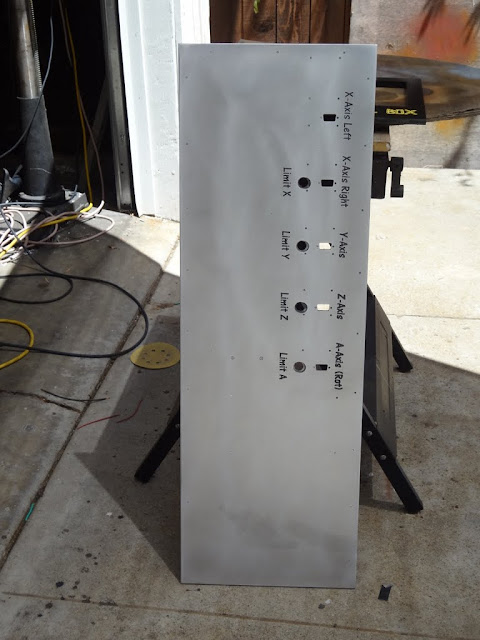
New Electronics Control Box Started
After several electronics modifications, adding a linear power supply and 4th axis control/drive with jury rigged wiring the machine looks pretty much like cr@p now:

Therefore I decided to start from scratch and build a new box to house all the components, including power supply, five 203V stepper drives, USB controller, spindle VFD, solid state relays for dust extractor and several control instruments. To allow for proper cooling, the back plate of this 12" x 36" box is 1/4" thick aluminum sheet, acting as one mighty heat sink for the stepper drives and SSR. There will also be a fan with dust filter to remove the heat generated by the power supply and VFD.
Side walls are 3/8" Garolite so I guess the box will be ample strong....

So far so good, now all to be assembled with aluminum angles and then the dreaded re-wiring
-
08-29-2011, 10:43 PM #17
Registered
- Join Date
- Jan 2006
- Posts
- 628
Ah, yes those load ratings should do nicely.
Your chances of losing steps with those monsters pushing things around seems pretty unlikely. A complete driver/motor failure is also pretty unlikely, but the belt should help avoid racking in either case. Makes sense.
Steve
-
08-30-2011, 05:14 PM #18
Registered
- Join Date
- Aug 2011
- Posts
- 999
Agreed. But I mentioned already I am a bit paranoid. Originally Posted by stevespo
")
-
08-30-2011, 08:32 PM #19
Community Moderator
- Join Date
- Mar 2003
- Posts
- 35538
Do not disassemble them, or they will be worthless. They become demagnetized when taken apart.I did not disassemble one and therefore..............Gerry
UCCNC 2017 Screenset
http://www.thecncwoodworker.com/2017.html
Mach3 2010 Screenset
http://www.thecncwoodworker.com/2010.html
JointCAM - CNC Dovetails & Box Joints
http://www.g-forcecnc.com/jointcam.html
(Note: The opinions expressed in this post are my own and are not necessarily those of CNCzone and its management)
-
08-31-2011, 04:37 AM #20
Registered
- Join Date
- Aug 2011
- Posts
- 999
Originally Posted by ger21
O.K. thanks, did not know that.

 Reply With Quote
Similar Threads
-
7 x 10 project started
By blades in forum Mini LatheReplies: 125Last Post: 01-25-2017, 05:27 AM -
CNC Project Started
By NotSqueaky in forum CNC Wood Router Project LogReplies: 8Last Post: 09-10-2014, 12:41 AM -
New Project Started
By Rumblebelly5 in forum Joes CNC Model 2006Replies: 1Last Post: 09-15-2012, 10:50 PM -
My 4x8 project has started
By MetalHead6263 in forum Plasma, EDM / Other similar machine Project LogReplies: 37Last Post: 01-31-2012, 07:30 AM -
Started new project
By rustamd in forum DIY CNC Router Table MachinesReplies: 55Last Post: 05-31-2009, 04:12 AM
