


Hello all,
In the process of decide some basic structure issues, i have a couple of questions i really like you to comment / give your opinions:
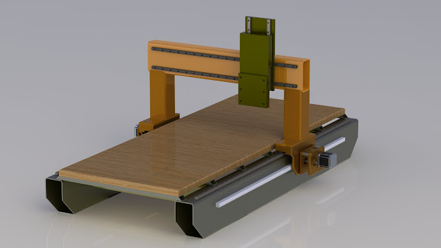
1- In the gantry itself, the rails position give a better support to the Z axis if they are both in the same plane (A) ("vertical position" ?), or in separate planes (B) (vertical + horizontal). I had some quick renders to explain what i am saying.
I guess it's easier to build in the same plane regarding the aligment right? Just wondering if option (B) give more support...
2- In the Z axis, i have seen using this two options for the rails: The "traditional" system with fixed rails and the trucks move along with the "Z plate" (option A), and the oposite where the trucks are fixed, and the rails are the moving part. I think the 1st option has the advantage of having a lighter Z plate (even considering the weight of the trucks), also the rails don't go so near the dust. In the other hand, in option (B), i wonder if the rails itself give a better stiffness to the Z plate, acting as a structure beam... Again renders of it.
Please give your opinions, that will help a lot deciding what design to choose. Even if you have other theorys, their welcome too.
Thank you for your help,
Rui
Results 1 to 12 of 12
-
11-20-2011, 05:43 PM #1
 Registered
- Join Date
- Feb 2008
- Posts
- 13
Need advice on basic structure decisions.
-
11-21-2011, 12:54 PM #2
Registered
- Join Date
- Oct 2008
- Posts
- 47
im building new one to and im in same boat .. but im 1st building z than worrying about all else ...
i almost have all parts .. just waiting on last critical pice and ill be able to start machining :P
-
11-22-2011, 03:32 AM #3
Registered
- Join Date
- Jan 2008
- Posts
- 853
I am not so sure about the weight argument. To be fair your (A) model should have a Z plate that extends down as far as the (B) model does, so the weight difference should be just the trucks vs the tracks. Not bringing the rails down near to the work seems like a reasonable point, but it is easy to add wipers. I don't think you should ever consider using the rails as stiffeners though ... use cheaper and stiffer material to do that for you, and use the rails just to slide upon. Originally Posted by nokode

When cutting near the lower limit of Z the two models have similar stiffness because the support-tool distances are the same. The (B) model gets stiffer when cutting up high, while the (A) model has a constant support-tool distance, and so its stiffness doesn't improve with Z.
Cheers!
-
11-22-2011, 02:34 PM #4
Registered
- Join Date
- Feb 2008
- Posts
- 13
Hi,
thank you for your comments. Regarding to the Z plate size, in my 3D sketch i didn't care about that, just the rails positional issue, but yes, you are right about that question.
If we consider both Z plates (on A and B options), the same size, could we say that when making lower cuts (more extended plate), the stress on the plates should be more or less the same, on both examples? There is no good reason to choose one or the other design?
Again, thank you for your help,
Rui
-
11-23-2011, 02:19 AM #5
Registered
- Join Date
- Jan 2008
- Posts
- 853
I don't see much difference wrt stiffness when close to the table. are there any adjustments on your trucks that require access?
-
11-23-2011, 07:26 PM #6
Registered
- Join Date
- Apr 2010
- Posts
- 363
Those solidworks models? How reluctant would you be sharing your rail files? Mine are really basic and I don't have the sketches for the shoes. I can give you the model for my whole table if you wish:
Just show me what changes you have made, cause I am always trying to improve this design.
To answer your question- when you look at a lot of the high end routers they tend to go with the two rails on the front of the surface. After wrestling with this question quite a bit I decided to go with with this method. There could be an alignment argument with having one rail at the top, which might be handy but for me it has not been a problem.
Here is mine:

I would recommend switching to a steel rectangular on your beam. I am a very firm believer in weight, and weight being good on your gantry. Weight makes things stiff, does not vibrate as much, and does not suffer from tool deflection.
As far as mounting your shoes on the stationary Z plate and the rails on the movable plate, I also considered this. For some reason I decided not to do this, and it was a fairly big reason that made me abandon the idea fairly early on. I think it had to do with assembly, and would have required me to takes the shoes off of the rails in order to assemble. (big no-no) In my last router I made a few nuts and bolts really hard to get to, no matter which order you assembled things and since then I have taken a good hard look at being practical to assemble when I put things together.
Hope this helps, feel free to ask more questions. I will keep an eye on this thread.
-
11-23-2011, 07:31 PM #7
Registered
- Join Date
- Apr 2010
- Posts
- 363
FWIW, here is one I made this last weekend:
I might sell it. It was mainly a proof on concept. I don't think it will fit the shoes I have on order, as this one is 6" wide and might be a wee bit narrow, so I might end up building another one. It's made of solid steel, and um...solid.
-
11-23-2011, 09:28 PM #8
Registered
- Join Date
- Feb 2008
- Posts
- 13
Don't consider this message.
-
11-23-2011, 10:44 PM #9
Registered
- Join Date
- Sep 2011
- Posts
- 0
I think it would be easier for you to have the rails in the same plane because if they are mounted on a common plate you dont have to worry about misalignment in 2 direction, only 1. If you have them in the same plane, you can just mount a dial gauge on one rails to determine the consistent distance (parallelism) of the other rail
-
11-23-2011, 11:31 PM #10
Registered
- Join Date
- Apr 2003
- Posts
- 540
I'm not a structural engineer but based on my knowledge and experience...
1. Each type and model of linear bearing has specific friction, wear, load bearing and efficiency characteristics. So, the answer would depend on the specific rail and bearing combination. Once you have decided on your rail/bearing system, the manufacturer should be able to provide specific guidance and data for your application. With some types it may make little or no difference and whatever suits your design would work. Other types of bearings like those with connected rails/open bearing (as opposed to a shaft and full circular bearing) may be less efficient based on side forces vs top or vice verse etc.
2. There would be little difference in the two z axis configurations except possible weight differences of your movable spindle mount itself. Again depending on the type of bearing. Normally, the rail or shaft would be mounted to the main structure and the bearings mounted on the part the moves. One way or another may fit your design better, but consider ease of adjustment, part replacement, lubrication and in the case of flying wood and metal dust, which would be easier to keep/stay cleaner.
I realize not much of an answer to your questions but for a good setup, any and all would work fine. A square build and well aligned table/bearings and good motors, balls and screws will have much more impact on your system than these placement differences when all is said and done. Look through other folks builds that have had success and pick out one you like and stuck with that basic design! Good Luck
-
11-24-2011, 12:02 AM #11
Registered
- Join Date
- Feb 2008
- Posts
- 13
Hi, Originally Posted by crane550
the solidworks models i'm using, you can download them from Free 3D Models, Free CAD Models, search for Hiwin (or go from here: Search Results: hiwin), just download matching carriage + rail profile. Hum... i think you have to register, but easy deal. The rails comes in 1000mm flavor, and i'm a beginner in SW, so i didn't figured out how to change length (if possible at all), so i made a new 25mm rail profile. If you want i can make the rails for you, just tell me the carriage size (if Hiwin), and rail length.
I haven't made my machine model yet, just in the process of collecting info, to decide the basic structure questions, and avoid future dead end issues.
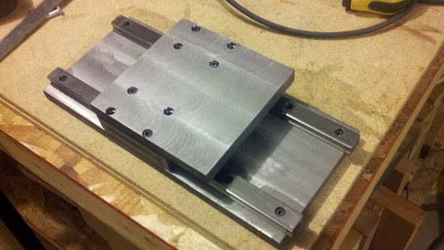
About using rectangular steel, i thought using that, BUT, usually, tubing is rolled and generally doesn't leave a perfect straight surface... and that can become a problem in the aligment process. I was thinking on using laser cut 12 to 15mm steel plate, with structural reinforcements like the photo. It's heavy for sure, and stiff enough i believe (but expensive... must think carefully).
I like your design, but i think i go with ballscrew instead of rack+pinion. What's the length of your X? Do you think R+P can offer the precision of ballscrew?
Cheers,
Rui
-
11-24-2011, 12:18 AM #12
Registered
- Join Date
- Feb 2008
- Posts
- 13
Hello,
the type of linear material i pretend to use should be profile rails + carriages from Hiwin, maybe 25mm for X axis, and 20mm for Y and Z axis. The info i found on these doesn't specify if we can use it in any position, in this case, in "vertical" position (the usual position seen in gantry), or if it's better used in flat horizontal (i don't know if i'm explaining well). Almost everybody uses in vertical position, so i guess it's ok... right?
Thank you all for your comments,
Rui

 Reply With Quote
Similar Threads
-
Decisions, Decisions, Decisions
By KnotsAboutWood in forum Open Source CNC Machine DesignsReplies: 7Last Post: 01-31-2011, 01:10 AM -
Which lathe decisions, decisions
By cornbinder23 in forum Benchtop MachinesReplies: 8Last Post: 12-16-2010, 05:41 PM -
Decisions, Decisions...
By WannaBe3D in forum DIY CNC Router Table MachinesReplies: 14Last Post: 07-31-2010, 03:30 PM -
decisions
By stinker in forum Benchtop MachinesReplies: 6Last Post: 09-14-2009, 04:13 PM -
Decisions, decisions
By ranchak in forum Uncategorised MetalWorking MachinesReplies: 4Last Post: 05-26-2009, 02:10 AM
