


Can someone please answer me why the bases from Q1 and Q2 are connected together over 470 ohm resistor? same with Q3 and Q4?
I am making microstepping project based on this schematic but I am confused because if I do this the two PWM signals from the MCU will be mixing and the two coils won't get the right voltages. anyone?
This is the simulation I've done and the results are expected.

Results 1 to 20 of 26
-
02-22-2012, 02:47 PM #1
 Registered
- Join Date
- May 2007
- Posts
- 35
Question about linistepper schematic
-
02-22-2012, 04:03 PM #2
Registered
- Join Date
- Oct 2005
- Posts
- 2392
It's not PWM coming from the micro it is an analogue voltage.
Q1 and Q2 bases are connected together so both transistors can be driven from the same analogue voltage, but one of them is turned off because its base will be pulled to ground by Q5 or Q6 ("killer" transistors).
-
02-22-2012, 07:59 PM #3
Registered
- Join Date
- May 2007
- Posts
- 35
 Originally Posted by RomanLini

As far as I know analog voltage from microcontroller is only possible by PWM?
-
02-22-2012, 08:06 PM #4
Registered
- Join Date
- May 2007
- Posts
- 35
BTW the PWM generator in my circuit is working nice. I measure it at 50% duty cycle and I get about 2.5V. Originally Posted by DigiSoft
Whatever you do I think the output of Microcontroller is always PWM. If you measure it with oscyloscope I think it will show PWM.
-
02-22-2012, 10:10 PM #5
Registered
- Join Date
- May 2007
- Posts
- 35
OK another question. Do you use software PWM or hardware in linistepper?
-
02-22-2012, 11:19 PM #6
Member
- Join Date
- Mar 2009
- Posts
- 533
The way I read the schematic is that the micro's outputs RB0 to RB7 are digital outputs, ON or OFF. The analog function could be via R18-R20 & C5 and R21-R23 and C6.
I suspect that this circuit is not complete as presented.
PWM, I would guess, is done by the micro since no other frequency input is shown on your schematic.
-
02-22-2012, 11:44 PM #7
Registered
- Join Date
- May 2007
- Posts
- 35
Yes I also think like this but I think he uses those resistors only to make 6th stepping "hardware" steps. So that is not accomplished by software microstepping. He says that he can make 8th microstepping by using PWM. But I don't see how is that possible. PIC should make 4 different PWM signals for the 4 coils. This PIC DOES NOT have 4 PWM pins. Originally Posted by KOC62
I can't understand this from the code because it is written in the stupid ASM language.
Can someone explain it?
-
02-23-2012, 12:00 AM #8
Member
- Join Date
- Mar 2009
- Posts
- 533
Think of the diode-R-C network as a "sample and hold". Now you can make a staircase waveform to form many "steps" - depending on the timing of the circuit. You could even make a crude sinewave for a microstepping function.
-
02-23-2012, 12:06 AM #9
Registered
- Join Date
- May 2007
- Posts
- 35
I think he is using pins 10,11,12,13 from the PIC only to "bias" Q5, Q6, Q7, Q8 and change their output mV that goes to the BJTs. This way he make "hardware" microstepping. But I still don't understand how he can make "pure" PWM microstepping.
I understand the "hardware part" but I am confused with the PWM. He drives all 4 wires with PWM? Hardware or software PWM?The brain has control of which of the 4 transistors are ON,
and sets 3 possible current levels, enough to do 6th stepping
and give 1200 steps/rev with hardware alone. The software I
have provided also will do pwm and give 18th stepping, which
is 3600 steps/rev, almost stepless operation.
-
02-23-2012, 12:54 AM #10
Member
- Join Date
- Mar 2009
- Posts
- 533
Very high resolution microstepping is forming sine and cosine waveforms, or pure sinusoidal waveshapes. Lowering the resolution makes the waveform more "digital" in that small steps can be seen in the sinusoidal waveshape. The lower the resolution the "clunkier" the steps.
To create the sinusoidal waveshapes there needs to be something that emulates a DAC (digital-to-Analog-Converter). That is what I believe is done with the diode-R-C network.
I haven't spent the time with your schematic to work it through, but I doubt it is just for "bias"ing the transistors, especially when I see the diode networks.
-
02-23-2012, 01:57 AM #11
Registered
- Join Date
- May 2007
- Posts
- 35
(digital-to-Analog-Converter). That is what I believe is done with the diode-R-C network.
Now that is interesting. Hmmmmmm I wonder hows that done :S without PWM.
-
02-23-2012, 02:41 AM #12
Member
- Join Date
- Mar 2009
- Posts
- 533
For example let's take one capacitor, C5. It is wired to 5V via R4. Also assume that IC1 pin 13 and pin 12 are high. C5 now has two more resistors in parallel to R4 (ignore the diode for now). This will give a time constant of 214usec. Hence C5 can reach 5V in 1millisec. Practically a bit less since the diode can clamp the upper limit, so say 4V in 1 ms.
With RB7 and RB6 output low the lowest voltage across C5 will be around 2V. Q5 can turn Q1 off. Hence there is a range of Q1 current steps via RB6, RB7 and RB3.
-
02-23-2012, 12:51 PM #13
Registered
- Join Date
- May 2007
- Posts
- 35
OMG but this type of micro-stepping is very not-precise. There are so much factors that can change the microstepping. Temperature of the components, VERY small variations from the power supply, quality of the components. This is no way to make microstepping. The only reliable variant is to use PURE PWM signal and FETs to drive the current and voltage. Originally Posted by KOC62
BUT STILL Why do I think that he gets PWM at the outputs of the BJTs?
There is no way that he can convert the digital PWM to "clean" voltage. Now if he biases the bases of the transistors with PWM "voltage" Then at the collector of the transistor he gets PWM AGAIN. So the voltage at the collector will be different because he outputs PWM.
Argghhh I am very confused. If only someone can explain this PWM <-> FET <-> BJT driving think.
-
02-23-2012, 03:03 PM #14
Member
- Join Date
- Mar 2009
- Posts
- 533
I'm not that familiar with the Linistepper. I'm basically going with your circuit. So I mentally strip away any circuit clutter to get the basic circuit function.
The only analog voltage that exists in your circuit is on C5 and C6. The base of Q1 (and the base of Q2) is fed from C5.
A bipolar transistor is a current device, meaning it takes a base current to control the collector current. The emitter voltage has to follow the base voltage minus the Vbe drop. Once you know the emitter voltage you can calculate the emitter current. If you mentally remove the circuit clutter and just see C5, Q1 and its emitter resistor, you should also see a basic constant current generator. The Q1 and Q2 collector current is controlled by the voltage on C5. To change the motor current you either have to change the emitter resistance or the voltage on C5. Well, the emitter resistor is fixed. Therefore only the voltage on C5 changes the motor current.
Since the voltage on C5 has a limited swing, the emitter resistor must be carefully chosen to control the collector current for its desired current swing.
What can possibly control the voltage on C5? Only the diode-resistor networks. The firmware must modulate (ON, OFF) the diode-resistors such that the C5 voltage changes. This change will also change the motor current. Whether you call this PM or some other thing is not important to me for circuit understanding. But since I see micro-stepping as a form sinusoidal current drive I was looking circuit components that could possibly do that.
Precisely what the C5 voltage looks like I haven't fully determined because it will take more work on my part. I was merely helping you understand the constant current behaviour of the circuit you provided.
Practical aspect will emerge when one tries to build the circuit, as you already pointed out, such as power supply changes, transistor temperature changes, etc. This circuit may require heavy heatsinking to minimize temperature shifts in the transistor.
There are not FETs here so I don't see the need to discuss them.
-
02-23-2012, 04:02 PM #15
Registered
- Join Date
- May 2007
- Posts
- 35
I think that C5 and C6 are there just to smooth out the voltage ramping so the final sinusoidal would look more AC analog then digital. (to remove the stairs looking sinusoidal).
Now it is true that you say about the diodes and the resistors and I think you are right but if we take that as correct then there are not many possible current combinations he can make over that resistor-diode grid. Maybe about 4 microsteps and no more. There is no way he can make 8 or more micro-steps only with MCU sending +5V or 0.
If he uses PWM then how? Because this PIC has only one hardware PWM pin.
I would like to see post from roman and see his opinion.
BTW why are there no protective Back EM diodes at the output BJTs? Is this complete circuit?
PS: I am making multisim simulation of this grid and I'll post results.
-
02-23-2012, 05:12 PM #16
Member
- Join Date
- Mar 2009
- Posts
- 533
C5 (and C6) does do a "smoothening" because it behaves like an integrator.
Secondly, this is an analog, or linear current controller, not a chopper.
Hence, we are not suddenly cutting the coil current as a chopper does so in this case it doesn't produce voltage spikes like a chopper circuit does.
Because this circuit is a linear current drive it doesn't use PWM to control the motor current as a chopper circuit would. It uses an emitter resistor to limit the current flow. This circuit has no feedback to tell the micro that the motor's maximum current has been reached.
You will have to analyse the firmware to get a better understanding of what the effective PWM is doing. That I have not done.
-
02-23-2012, 05:39 PM #17
Member
- Join Date
- Mar 2009
- Posts
- 533
One other thing.
The micro uses one byte to control 8 output bits. All 8 bits control the constant current generators in some fashion. We only touched on the diode-resistor network as part of this. So for completeness you will need to factor in all 8 bits in your simulator to model this circuit. The firmware pumps out a byte every so often. I don't know if this occurs in a steady stream, or if this has an "erratic" looking stream of bytes. There is no feedback to the micro so the micro is blind as to what is going on outside. The micro only sees the STEP and DIR pulses to know how fast to spit out the "current control" byte.
-
02-23-2012, 06:01 PM #18
Registered
- Join Date
- May 2007
- Posts
- 35
Originally Posted by KOC62
Yes that is exactly what I am simulating right now.
-
02-23-2012, 06:10 PM #19
Registered
- Join Date
- May 2007
- Posts
- 35
OMG the circuit works I've got 6 microsteps WITHOUT PWM.
I reproduced this
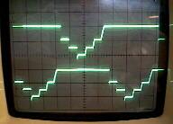
But can't do this
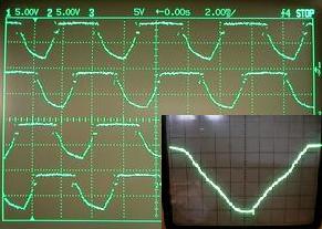
-
02-23-2012, 06:21 PM #20
Community Moderator
- Join Date
- Dec 2003
- Posts
- 24220
I assume you have read these two sources?
LiniStepper, lini, stepper, linear, 6th microstep, linear microstepping stepper motor driver, constant current linear driver, circuit Linistepper boards, LiniStepper kit, hobby stepper, robot stepper driver kit, CNC stepper driver kit
PIC Linear Stepper Motor Controller
The source code is included.
Al.CNC, Mechatronics Integration and Custom Machine Design
“Logic will get you from A to B. Imagination will take you everywhere.”
Albert E.

 Reply With Quote
Similar Threads
-
Question about Linistepper v2
By tomovsb in forum Open Source Controller BoardsReplies: 33Last Post: 07-24-2017, 10:38 PM -
Linistepper in C
By hazimin in forum PIC Programing / DesignReplies: 9Last Post: 01-24-2011, 03:34 AM -
Quick Schematic Question
By Cartierusm in forum PIC Programing / DesignReplies: 6Last Post: 01-18-2009, 12:06 AM -
Linistepper
By tante in forum Open Source Controller BoardsReplies: 7Last Post: 12-19-2005, 04:24 PM -
CNC router wiring schematic question.
By CRFultz in forum CNC Machine Related ElectronicsReplies: 3Last Post: 11-26-2004, 06:22 PM
