


Hi guys -
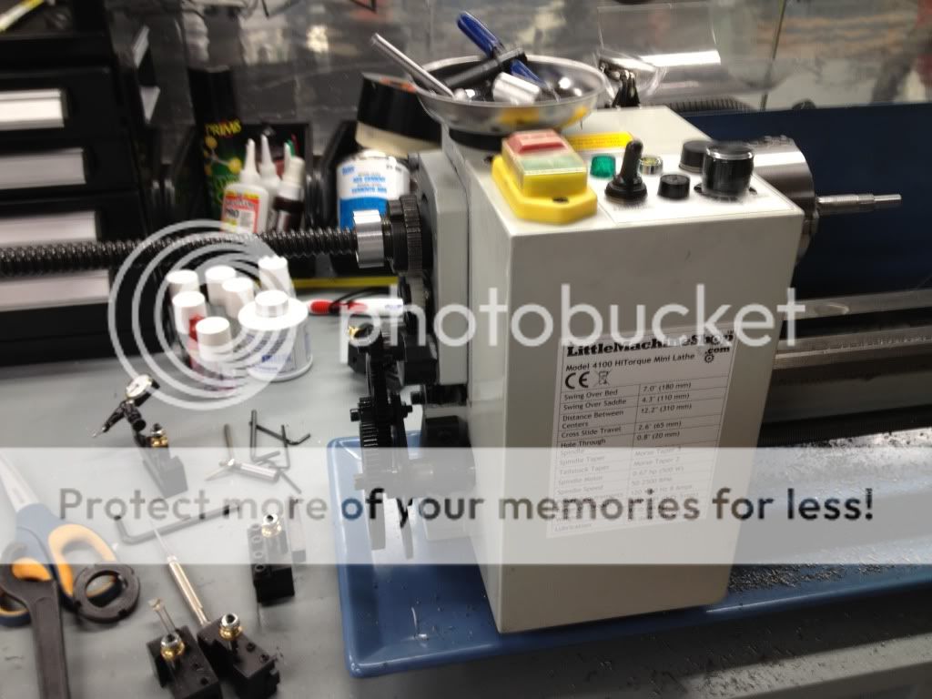
I have been lurking in this forum for quite some time, and finally pulled the trigger on an LMS solid column HiTorque Mini Mill as well as a HiTorque Mini Lathe. I have never done any machining before, but am anxious to learn. After watching numerous youtube videos and reading a couple of machinist books, I started learning to use the tools. My first big project, of course, is to convert the mill to CNC.
I thought about just purchasing the CNC Fusion kit, but I felt that for the price I could take it as an adventurous learning experience and build something myself. Also there are just a couple of things that I am not fond of with the kit - the extension to the X-axis, covering up the Z gibs, and the preloaded bearing mechanism.
Rather, I decided to grind away some material on the underside of the table in order to fit the ballnut mount inside the carriage, eliminating the table extension. I also followed the preloaded angular contact bearing methodology found on CNC cookbook: CNC Cookbook: Eliminating Backlash, Part 1
Well, I started this journey about 3-4 weeks ago, so I will post some pictures now. Unfortunately, I got deep into the work at various points and forgot to take pics.
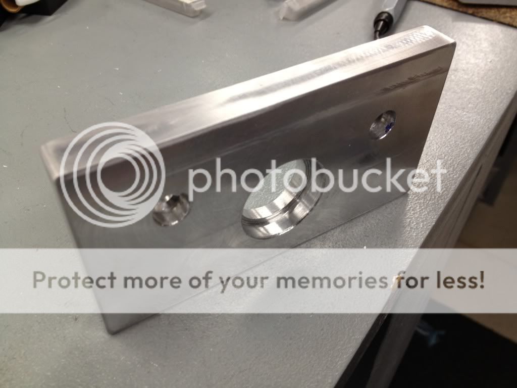
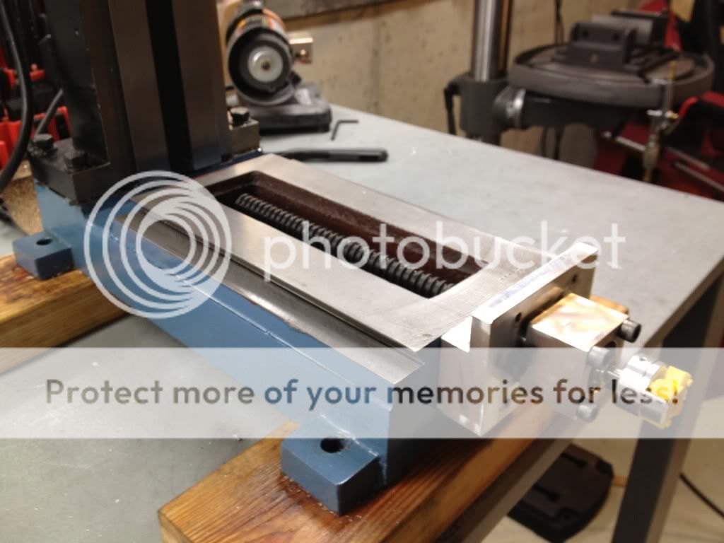
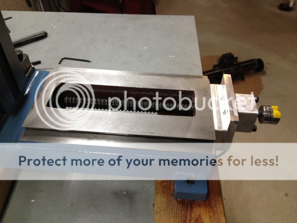
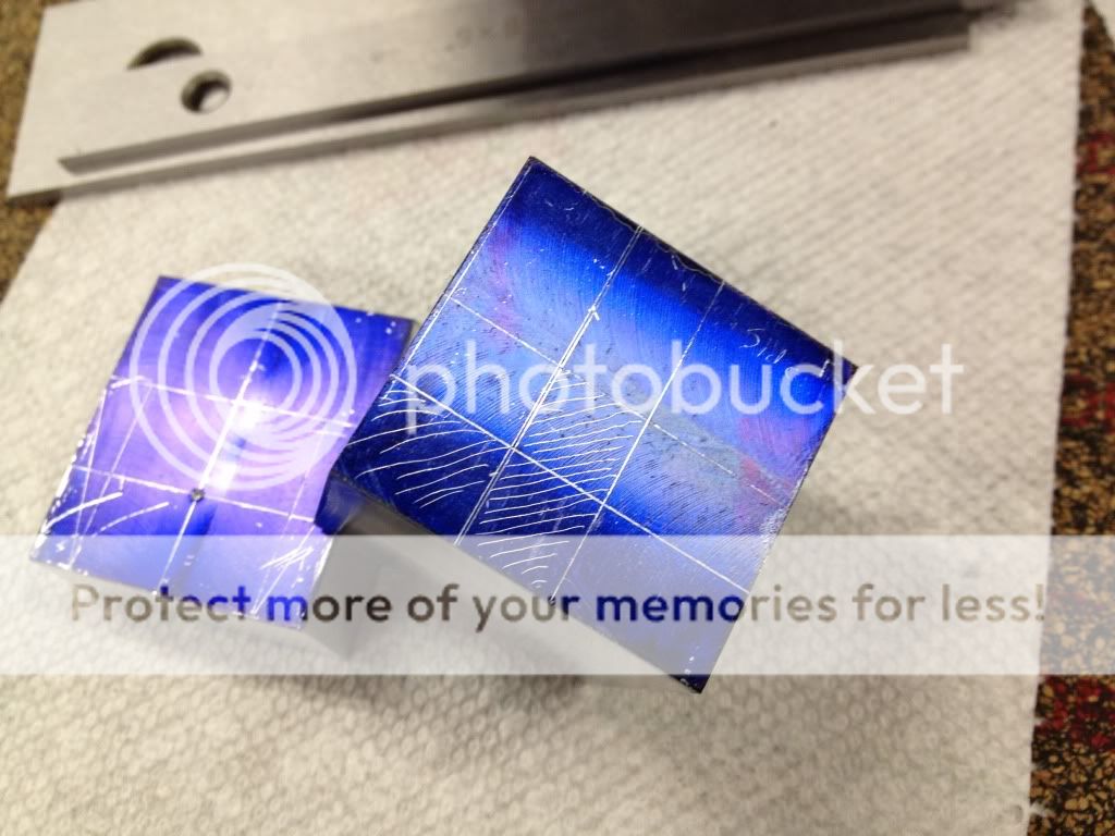
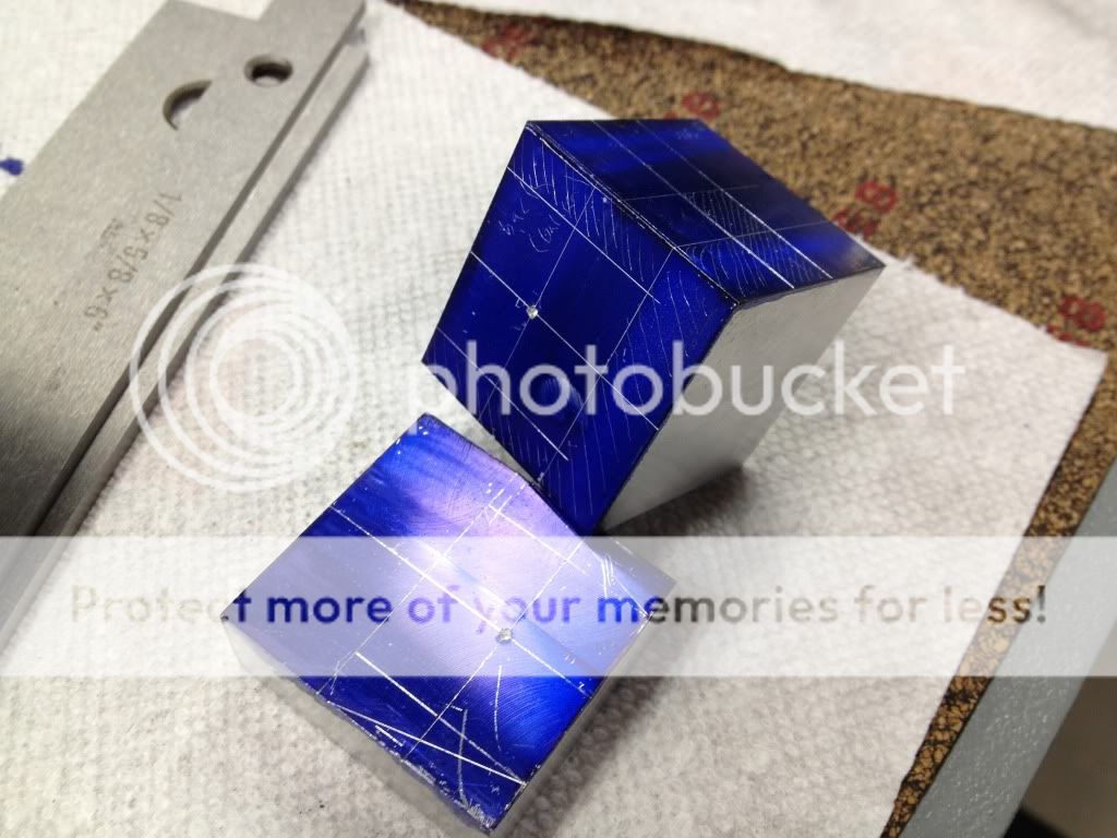
Laid out my first couple parts - X and Y ballnut holders
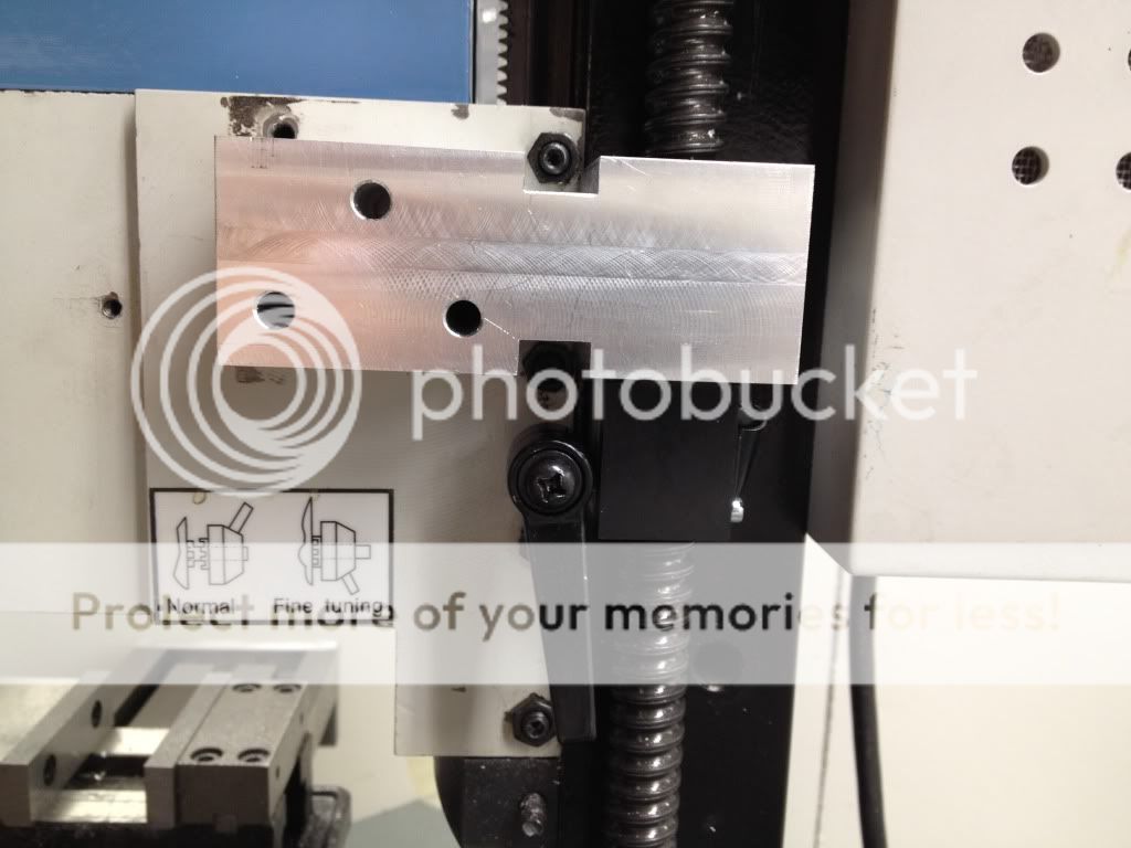
Test fitting and grinding down the table a bit for fitment

Thread: My SX2 CNC build! (lots of pics)
Results 1 to 20 of 38
-
03-09-2012, 04:33 PM #1
 Registered
- Join Date
- Nov 2011
- Posts
- 0
 My SX2 CNC build! (lots of pics)
-
03-09-2012, 04:37 PM #2
Registered
- Join Date
- Nov 2011
- Posts
- 0
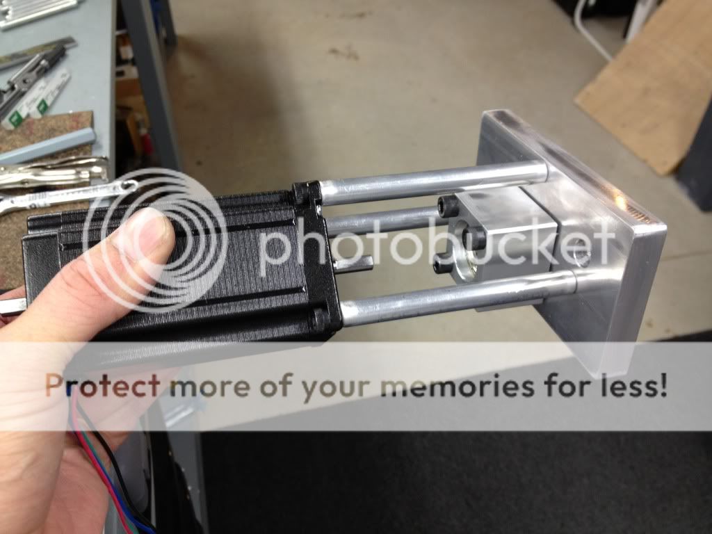
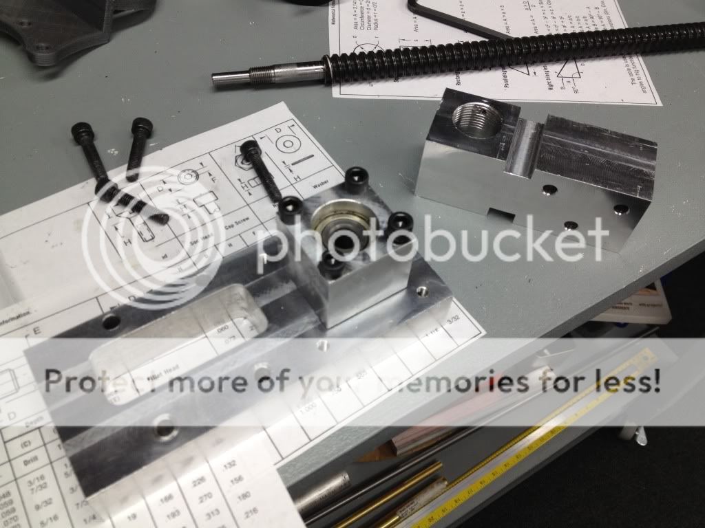
Making X table ends and bearing holders. Wanted to use dual preloaded angular contact bearings.

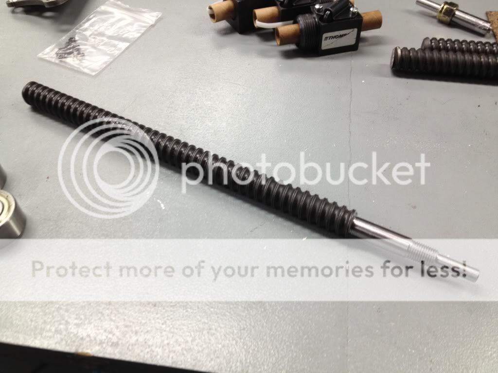
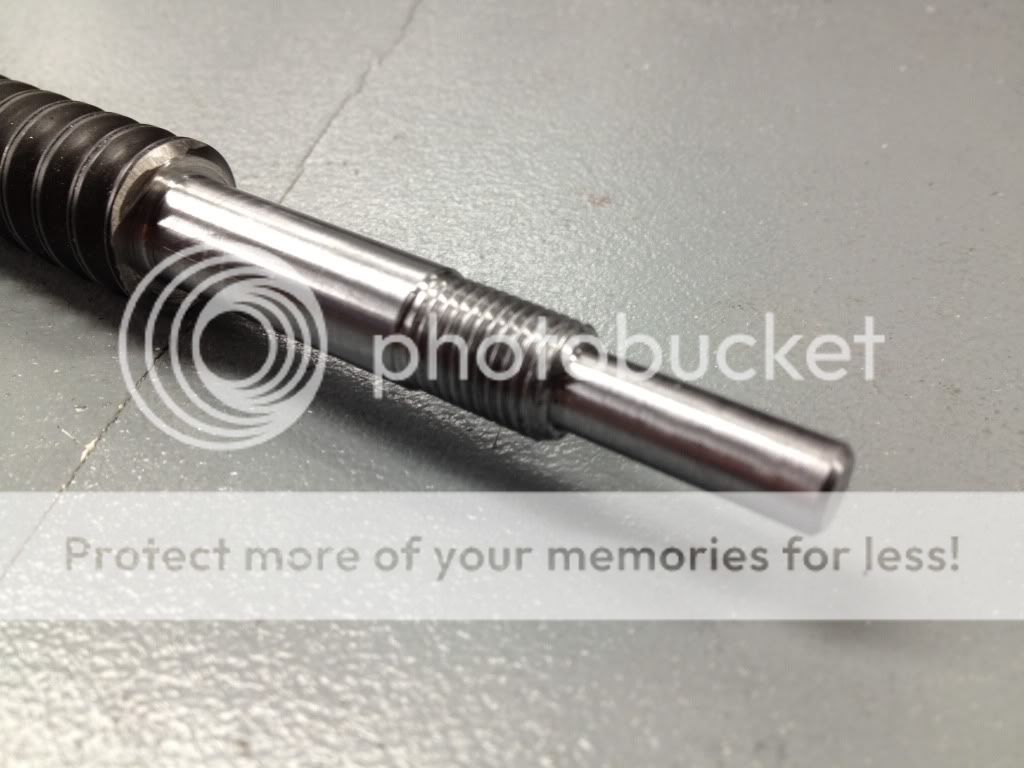
Since I only have a Mini lathe, My attempts at machining the ends of the ballscrews were rough - it could be done, but at a very slow and index-breaking pace
So I cut them down with an angle grinder, faced the end, and drilled and tapped a hole. Then made a threaded end out of steel and attached it to the end of the ballscrew with red loctite. 24 hours later, i chucked the whole thing in the lathe and machined the ends. Here is a small trick I used to hold the 2 ft lengths securely in the chuck without wobbling


-
03-09-2012, 04:40 PM #3
Registered
- Join Date
- Nov 2011
- Posts
- 0

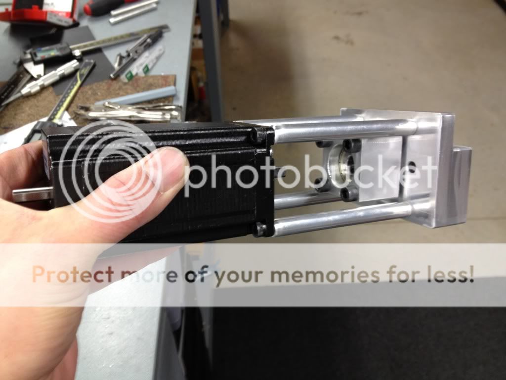
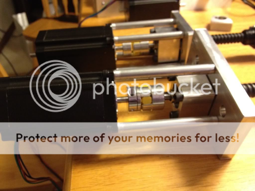
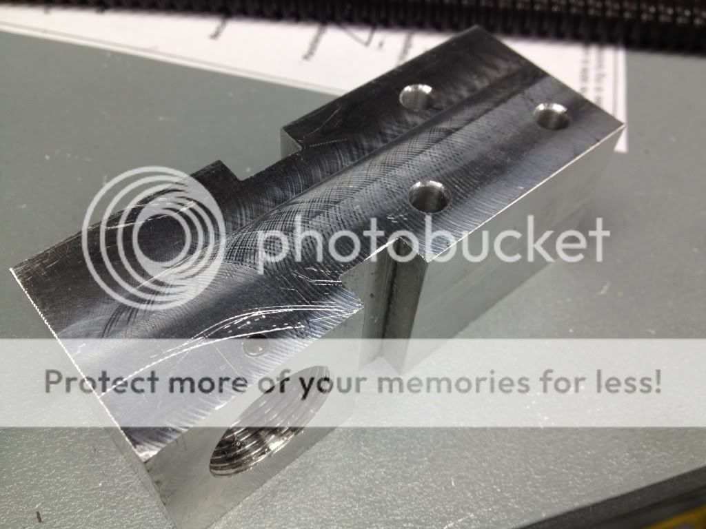
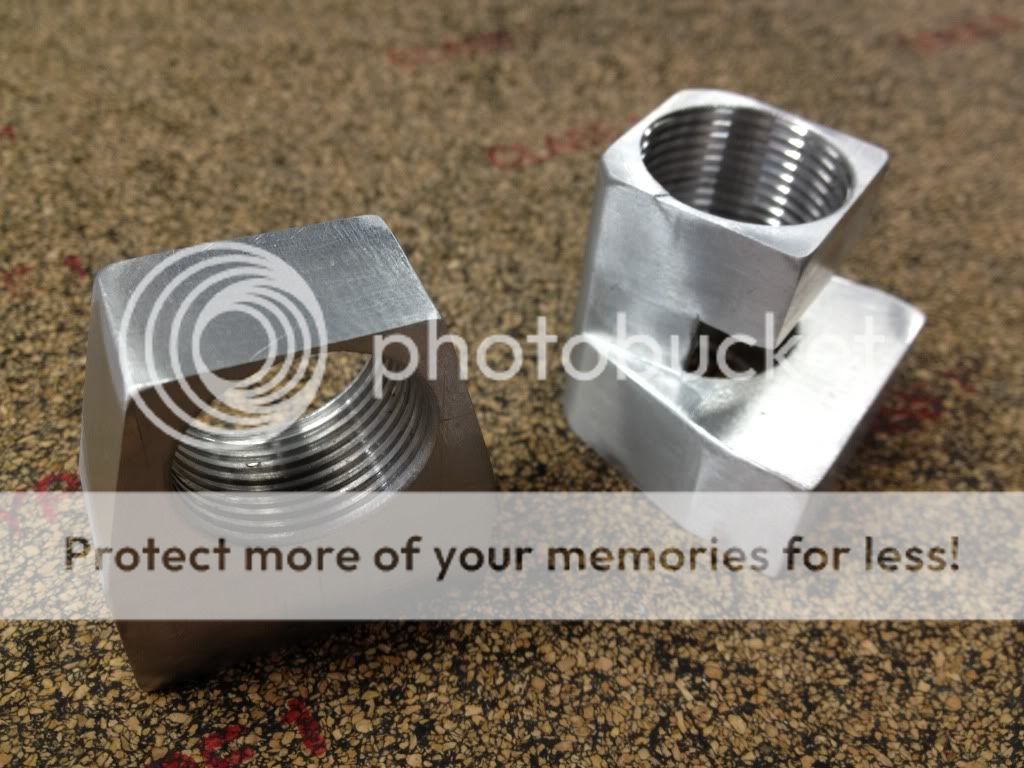
Here are the X and Y mounts with bearing holders after I got them all machined and assembled


-
03-09-2012, 04:53 PM #4
Registered
- Join Date
- Nov 2011
- Posts
- 0
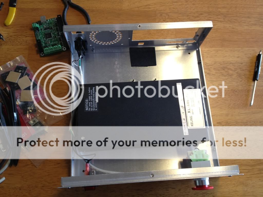
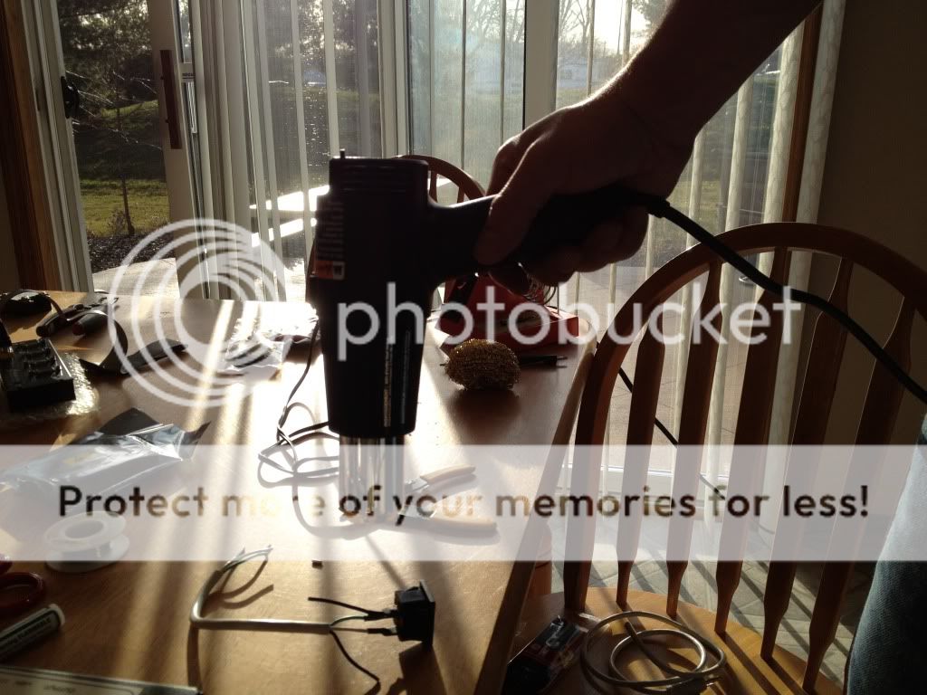
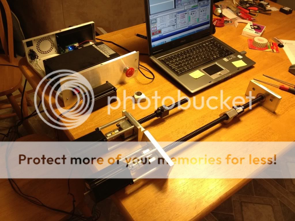
I then received a big order from Keling (AutomationDirect). It was a lot more work than I thought to put the controller box together. I carefully soldered all connections to ensure solid connections. I didn't take enough pictures but I also ended up putting a solid state relay for spindle control.


-
03-09-2012, 04:57 PM #5
Registered
- Join Date
- Nov 2011
- Posts
- 0
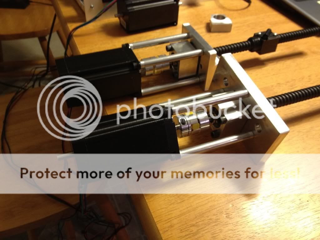
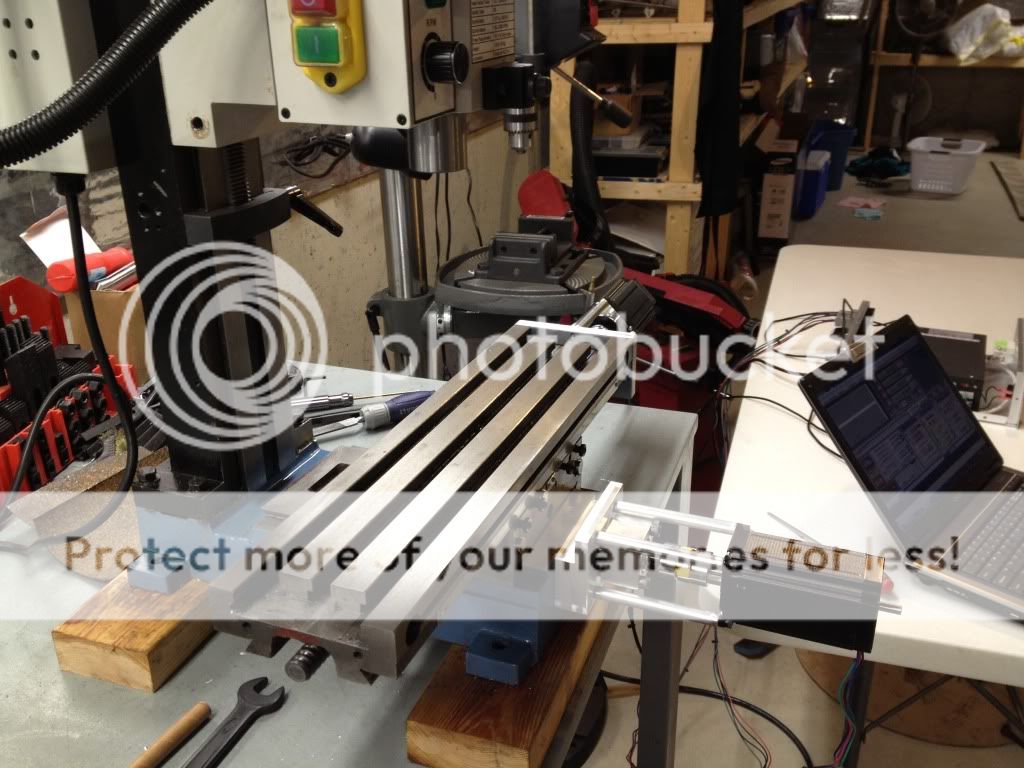
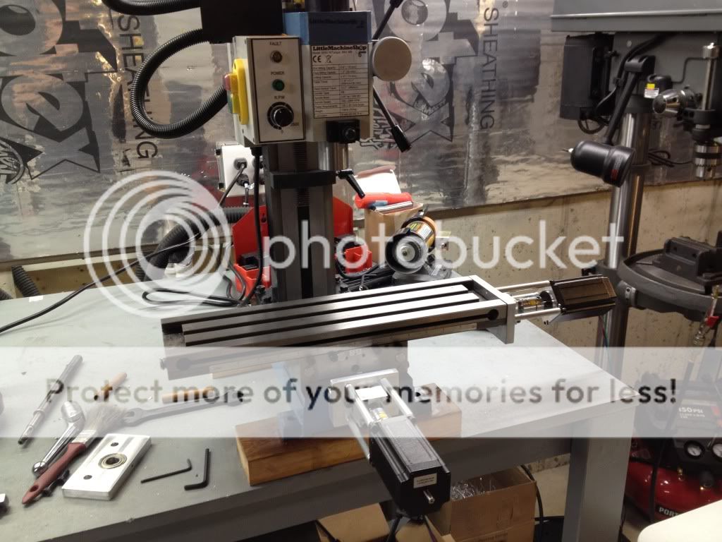
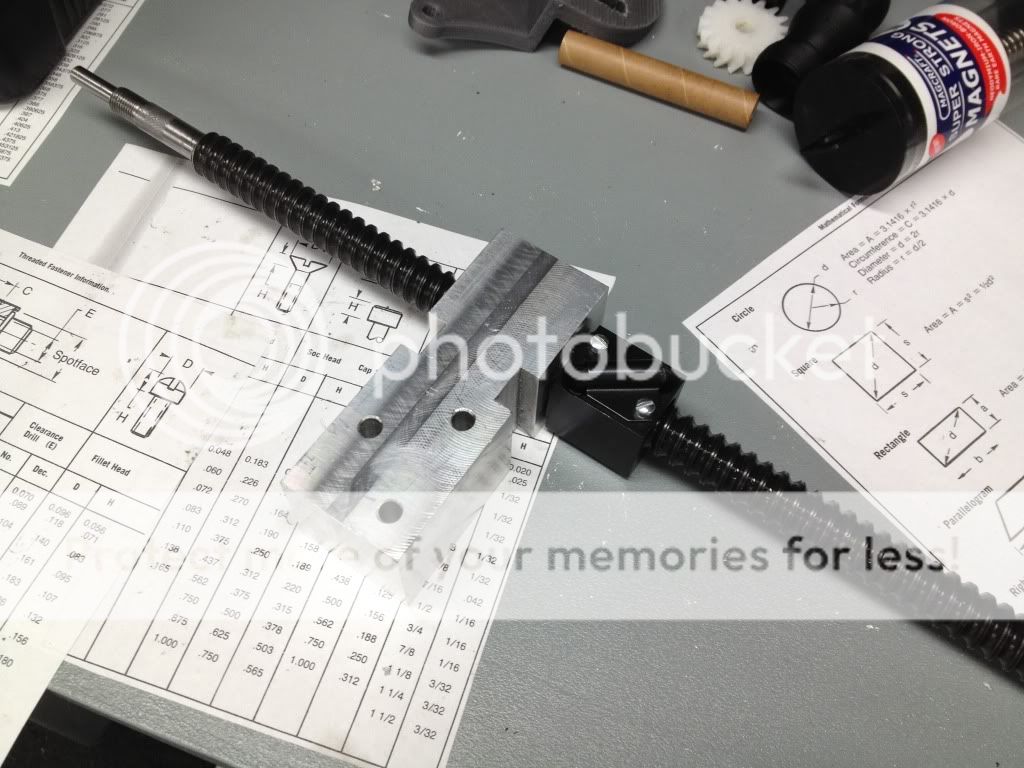
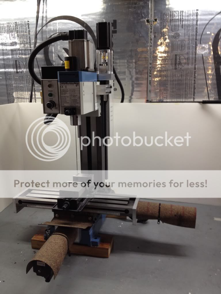
Finally, the X and Y came together!! I figured this would make the Z-axis parts much easier to fabricate.


-
03-09-2012, 04:59 PM #6
Registered
- Join Date
- Nov 2011
- Posts
- 0
Phew - that was a lot of pic posting!!!
So that's where I stand today. I have since gotten an XBOX 360 remote hooked up, and a better computer/monitor solution. I am now going to work on the Z-axis parts, etc. Will post more pics in a few days hopefully!!

-
03-09-2012, 06:06 PM #7
Registered
- Join Date
- Aug 2003
- Posts
- 28
Very Cool !
-
03-09-2012, 07:38 PM #8
Registered
- Join Date
- Dec 2009
- Posts
- 1416
Fantastic work! I have a 10x22 lathe and I also used exactly that method to make the end of my Y axis screw anyway. No squeals, howls, groans and other noises from the lathe and once the lock-tite set that sucker was not going to budge, certainly not with the force a 570 oz-in stepper could produce.
CNC: Making incorrect parts and breaking stuff, faster and with greater precision.
-
03-09-2012, 09:39 PM #9
Registered
- Join Date
- Dec 2006
- Posts
- 839
Very nice job you are doing, great looking machine now to. Hope to see some of your work with it soon. (awsome job on the ball screws)
JessGOD Bless, and prayers for all.
-
03-10-2012, 02:15 AM #10
Gold Member
- Join Date
- Jan 2005
- Posts
- 1695
Nice work. How are you dealing with the ballscrew backlash?
-
03-10-2012, 12:34 PM #11
Registered
- Join Date
- Nov 2011
- Posts
- 0
Thanks for the comments!
As for backlash handling, currently I am still working on that. I preloaded the Thomson ballnuts (which come stock with .124" balls) with .125" balls. However, I feel there is room to go even larger, so I ordered some .1255 and .1257" balls to try out. I will do some experimentation until I get the optimal mix of preloading and low-friction. Currently, I am seeing around .006 " of backlash in each axis..
-
03-10-2012, 05:08 PM #12
Registered
- Join Date
- Dec 2009
- Posts
- 1416
Might check those couplers. I have heard several people complain of the backlash in those.
CNC: Making incorrect parts and breaking stuff, faster and with greater precision.
-
03-10-2012, 05:43 PM #13
Gold Member
- Join Date
- Jan 2010
- Posts
- 2141
I'm not certain from the photos, but aren't those Oldham couplers? Originally Posted by photomankc

-
03-10-2012, 06:25 PM #14
Registered
- Join Date
- Dec 2009
- Posts
- 1416
Looks like Spider couplers to me. Oldham has a single slot/key on each end. Spiders have the prongs with the X shaped peice in the middle.
I'd say measure the actual screw backlash by grabbing the table and push/pull on it to see how much it's moving. If that amount is anything less than what you are seeing when jogging it then you have to chase down whatever else is causing it. 0.006 sounds like a lot for brand new ball screws.CNC: Making incorrect parts and breaking stuff, faster and with greater precision.
-
03-10-2012, 06:57 PM #15
Gold Member
- Join Date
- Jan 2010
- Posts
- 2141
I guess that I missed that photo - lots and lots of photos on this page.
But I'm not complaining!
-
03-10-2012, 07:38 PM #16
Gold Member
- Join Date
- Jan 2005
- Posts
- 1695
I get .003-.004 of system backlash from the Thomson screws. I managed to reduce it to less than .001 by using 2 nuts. I'm also using the same Lovejoy type coupling. Unless the gibs are very tight, I found that they contribute less than .0005.
-
03-11-2012, 07:18 AM #17
Registered
- Join Date
- Dec 2005
- Posts
- 430
This mill is interesting. I don't see it on littlemachineshop's site. Only the tilting column version. It's basically an x2, right? With a BLDC spindle motor, and larger table? It would seem to be much stiffer without the tilting column.
EDIT: nevermind, just found it. hmmmmmShaun
my x2 conversion ------> http://www.cnczone.com/forums/showthread.php?t=36403
-
03-12-2012, 12:00 PM #18
Registered
- Join Date
- Nov 2011
- Posts
- 0
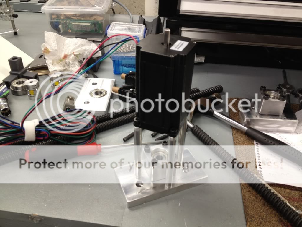
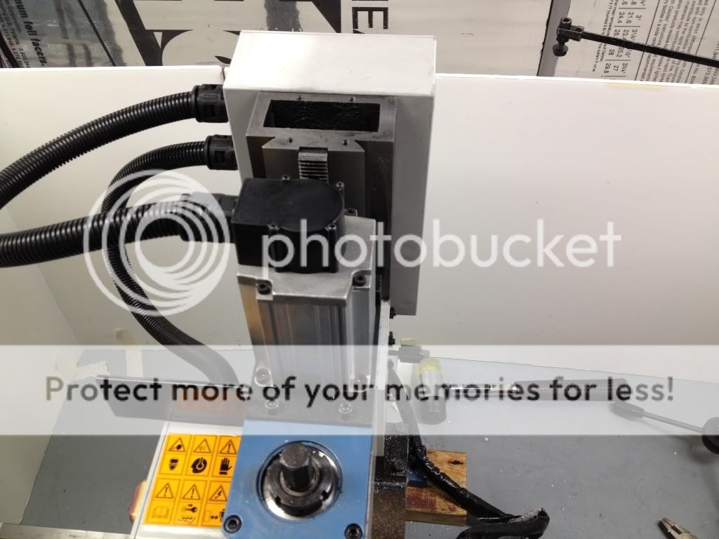
UPDATE: Z-AXIS COMPLETE!!! :cheers:
I stayed up most of the night Saturday finishing it up. I goofed up a little bit on the ballscrew mount (made 3 screw holes, 1 of them is right over the existing pinion geear shaft hole, oop - will have to make a new hole). Also, the only screws I had were too long, so in a pinch I made some small aluminum spacers to take up the slack. Will get some proper screws ordered up shortly
As for the Z-axis ballnut, I ordered some different sized bearing balls from Toolsupply, and it appears that the .1257 balls fit very snugly in the ballnuts - no binding, but virtually all backlash is gone!! YAY. Ordering more for the other 2 ballnuts.
Oh - and for the z-mount, the rectangular hole was made with plans of installing the air spring kit in after CNC'ing. However, with the 381oz/in motor I feel that this is totally unnecessary!
Here are the pics:


-
03-12-2012, 02:30 PM #19
Registered
- Join Date
- Jan 2012
- Posts
- 0
Looking good! Thanks for posting all the pics. I'm in the process of rebuilding my X2 with the intention of CNC'ing it, and I think I'll take a few note from your build.
Your Z-axis setup looks like it would work pretty well for me too, but what do you plan to go to protect the ballscrew from swarf?Chasing tenths is hard...
-
03-13-2012, 01:57 AM #20
Registered
- Join Date
- Jun 2011
- Posts
- 0
 Excellent
Mercyful heavens outstanding..... and you say you have no machining background, I love it and shrinkwrap over the soldered joints very professional and I'll bet you are enjoying it more too that you are machining your own parts and I see you are using the USB Smooth Stepper, keep the pics flowing and thanks for sharing:cheers:
Eoin


 Reply With Quote
Similar Threads
-
Custom CNC Controller System In A (Rackmount) Box! (LOTS of pics!)
By OddOne in forum Controller & Computer SolutionsReplies: 1Last Post: 12-22-2022, 02:24 PM -
Benchtop CNC lathe from scratch (Lots of pics warning)
By JH-Q in forum Vertical Mill, Lathe Project LogReplies: 191Last Post: 11-27-2012, 04:49 PM -
Help please, shallow DOC sucks noodles... LOTS OF PICS!
By Propaganda in forum PCB millingReplies: 13Last Post: 07-15-2010, 04:52 PM -
Started build on CNC Mill. Lots of pics, sorry.
By EvanZ in forum Uncategorised MetalWorking MachinesReplies: 3Last Post: 02-17-2008, 02:24 PM -
M.E. Project (pics, lots of pics)
By skmetal7 in forum Community Club HouseReplies: 2Last Post: 01-08-2007, 10:30 AM
