


Hi there,
I started lurking around after discovering Lenne's CN on BitTech about a year ago.
Since then I became a bit obsessed with building a CN.
At first, I dreamed myself building a huge one then the cost for such a machine bring me back to reality
so I planned to build a tiny one with drawer rail or so.
Eventually I decided to put some money in it to get something that would allow me to mill plastic, wood
and (I wish) 5mm alu plate even if I got to do it in severall time.
I began by buing this kit on ebay.
I am waiting for them to get started with the plans.SBR16-300/800/1300mm(6supported rails and 12 SBR16UU bearing blocks)
3pcs RM1605-350/850/1350mm with ballnuts and end machined
3sets BK/BF12 end support with locknuts and circlips
3pcs couplers 6.35mm*10mm
I will get the electronic once the frame is going to be usable.
Due to lack of money I intended to use MDF to build it, but I might have an opportunity to get some 40*40 & 40*80 alu
profiles, I'll keep you posted about that.
In the end I would like to get somthing like Lenne's V1
Sorry about if there are some mistakes, I'm still trying to improve my english.
Feel free to post any comments or suggestions.
Z
Thread: New build (I hope so) in France
Results 1 to 20 of 23
-
04-12-2012, 09:09 AM #1
 Registered
- Join Date
- Mar 2012
- Posts
- 16
 New build (I hope so) in France
-
04-12-2012, 06:50 PM #2
Registered
- Join Date
- Jan 2012
- Posts
- 35
I dont mind, but asking is always a good way to start if ure using other peoples pics.
-
04-13-2012, 12:11 AM #3
Registered
- Join Date
- Mar 2012
- Posts
- 16
asking is always a good way to start if ure using other peoples pics Trully sorry about that, I just wanted to "picture" what I intend to do since my sketches are not ready yet.
I didn't occured to me at the moment to ask you before using your pic.
Sorry again.
-
04-13-2012, 03:37 AM #4
Registered
- Join Date
- Oct 2004
- Posts
- 590
I wouldn't feel too bad. After all you're just linking and you did give credit. In the end it's the free exchange of information that makes this site work. Check out Mike Everman's posts and the generous way he's exposed all of the details of his proprietary development of the servo-belt drive. Originally Posted by Zm@steR

-
04-15-2012, 02:22 PM #5
Registered
- Join Date
- Mar 2012
- Posts
- 16
QUICK UPDATE
One of my coworker had a present for me
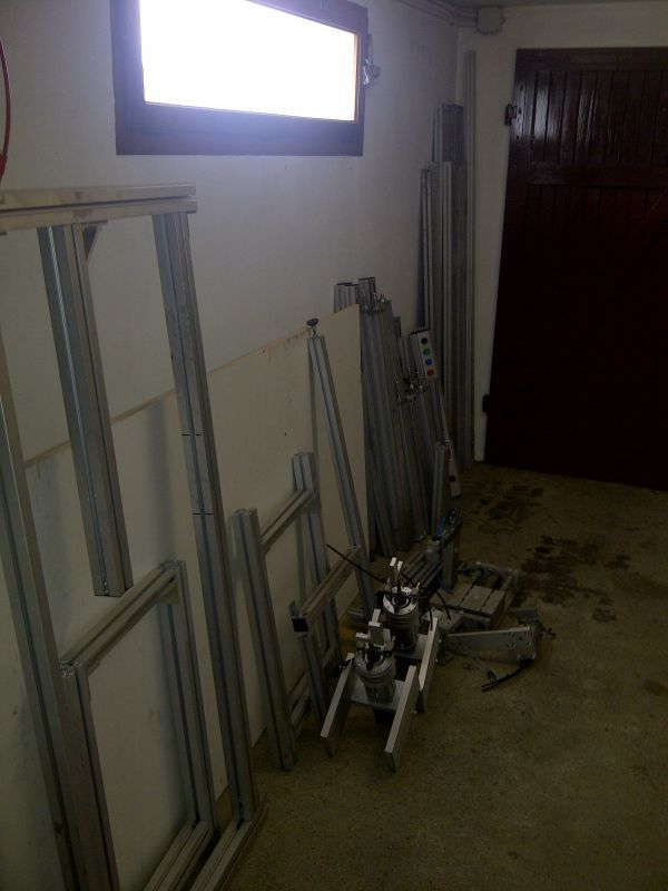
There are some 40*40, 40*80 & 50*50 alu profiles.
I am still waiting for the rails & bearings.
BTW does any of you have some tip about how I could fixe the rails ?
As I intend to use the 40*80 profile and the support of the rail is 40 at the base, it going to be tricky to tide them.
Z
-
04-17-2012, 07:59 AM #6
Registered
- Join Date
- Jan 2012
- Posts
- 35
Im not offended by it anyway, that was meant more as a tip in general, its always nice being asked if someone wants to use ur work for whatever purposes, sometimes i find it linked in the weirdest places Originally Posted by OCNC

back on topic, i do not really understand what ur mounting Problem is, maybe u can make a pic to show it ?
-
04-17-2012, 10:36 AM #7
Registered
- Join Date
- Mar 2012
- Posts
- 16
Ok not the best sketch but it will do the trick.
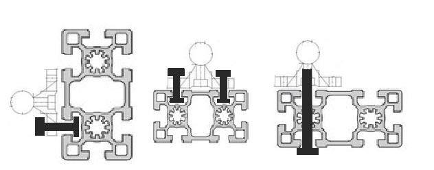
From left to right
- what Lenne did on his V1 (it seems to work fine for him but IMO it may be improved a bit)
- what would be perfect (but it would require to get a 30*60 alu profile)
- what I am currently thinking about (no idea if it's possible and suitable)
Hope it's clear enought.
Every suggestion/advice is welcome
Z
-
04-18-2012, 12:45 AM #8
Registered
- Join Date
- Jan 2008
- Posts
- 853
The middle picture shows how it is supposed to work, if the hole spacing works. The right may work, but it goes against the working ideas of using 8020 stock.
1) you are drilling through holes, and therefore not taking advantage of the extrusions flexibility with slots.
2) The std way of tightening with 8020 pulls the extrusion up against the bottom of what is being attached, increasing the contact area as you tighten; the extrusion is initially bent down towards the slots to make this effective. Your bolts are trying to compress the wall on the other side of the extrusion in toward the middle (ie in the opposite direction) without deforming towards the contact surface. You are concentrating the forces to a few contact points instead of distributing them to create contact surfaces.
-
04-18-2012, 06:30 AM #9
Registered
- Join Date
- Nov 2006
- Posts
- 1036
I'm no expert so take with a grain of salt. I think your option number 3 is suboptimal because tightening the bolt would tend to crush and deform your extrusion. When I mounted as SB20 rail on an 8020 extrusion, I made a steel adapter plate. The plate is bolted to the extrusion, the SB20 rail bolted to the steel adapter. Another builder simply tapped the 8020 extrusion and this seems to be working fine. Here's a link to his build: http://www.cnczone.com/forums/cnc_wo...tml#post985034
-
04-18-2012, 06:58 AM #10
Registered
- Join Date
- Jan 2012
- Posts
- 35
A big washer would solve that problem though, i would go for solution 3; u can unscrew the rail from the support and then drill and tap it. Originally Posted by DonFrambach
-
04-18-2012, 12:34 PM #11
Registered
- Join Date
- Mar 2012
- Posts
- 16
That's the problem, the hole spacing doesn't match. Originally Posted by PaulRowntree
Indeed, one other solution is to put a plane steel in the slot underneath the rail support, but I still have to drill threw the 8020 to screw the bolt from the bottom. Originally Posted by PaulRowntree
Thx for the tips I'll think about those. Originally Posted by DonFrambach
What do you mean by "drill an tap it" I just want to unscrew the original bolt and replace them with longer ones, so I will just have to drill the 8020 and the plane steel Originally Posted by Lenne0815
I will slide in the upper slot or underneath the 8020 and then rescrew everything.
-
04-18-2012, 01:13 PM #12
Registered
- Join Date
- Jan 2012
- Posts
- 35
Slide ? Originally Posted by Zm@steR
 i wasnt aware that ur supported rails already have threads for fixing them in the middle, mine didnt ( that makes it even easier ) and make sure u drill the holes through the 8020 a fair bit bigger than ur screws gonna be, otherwise u wont have a chance to align them properly later on ( this applies only if ur screw goes through the whole profile )
If ure going to drill the profiles anyway u could still mount them as shown in pic 2 it would just require some more holes.
-
04-18-2012, 01:57 PM #13
Registered
- Join Date
- Mar 2012
- Posts
- 16
Thx. As I said my english is kinda "work in progress"Slide
Me neither, it was just a guess based on the datasheets given on eBay since I haven't received them yet.i wasnt aware that ur supported rails already have threads for fixing them in the middle
But I don't know if chinese datasheets are any reliable.
We'll see for now I've started working on the global design I'll post the sketch asap.
-
04-18-2012, 04:10 PM #14
Registered
- Join Date
- Apr 2009
- Posts
- 266
not sure how you plan to support the extrusion that the rails are mounted to... but wouldn't the orientation of the option 2 and 3 make it more prone to flex whereas the option 1 will stay more rigid?
my first..."Big Ape" CNCRP 2448 Build Log
-
04-24-2012, 08:58 AM #15
Registered
- Join Date
- Mar 2012
- Posts
- 16
It's me again for a new quick update.
So here it is finally got my shipment, let's go unpacking it
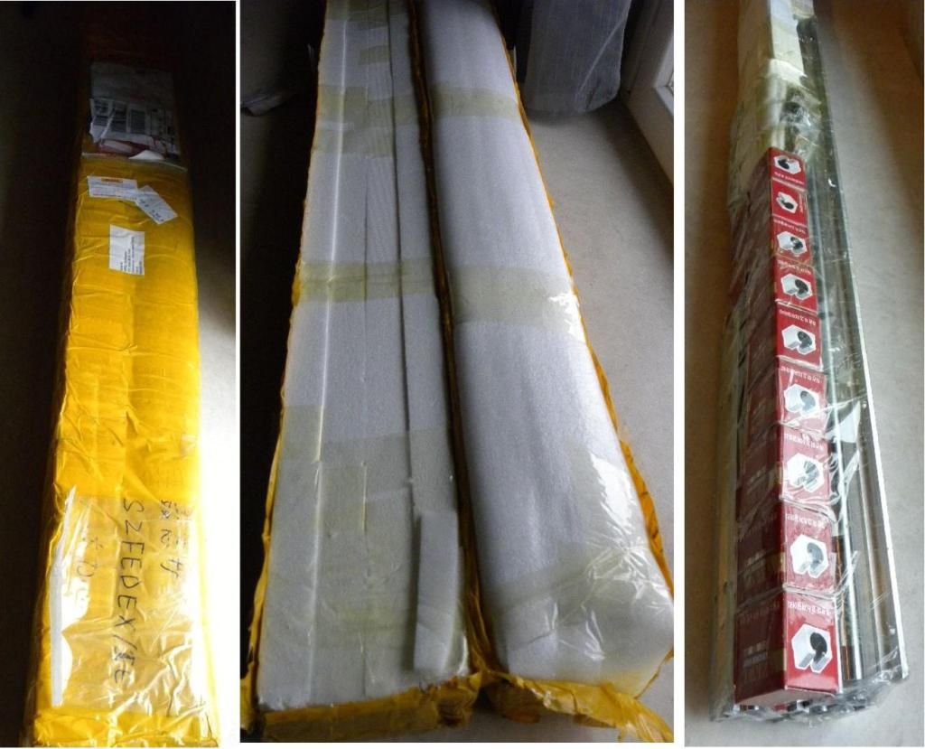
Seems well packed at least (there is a plastic sheet between the tape & the rail so no glue on them)
A global vue
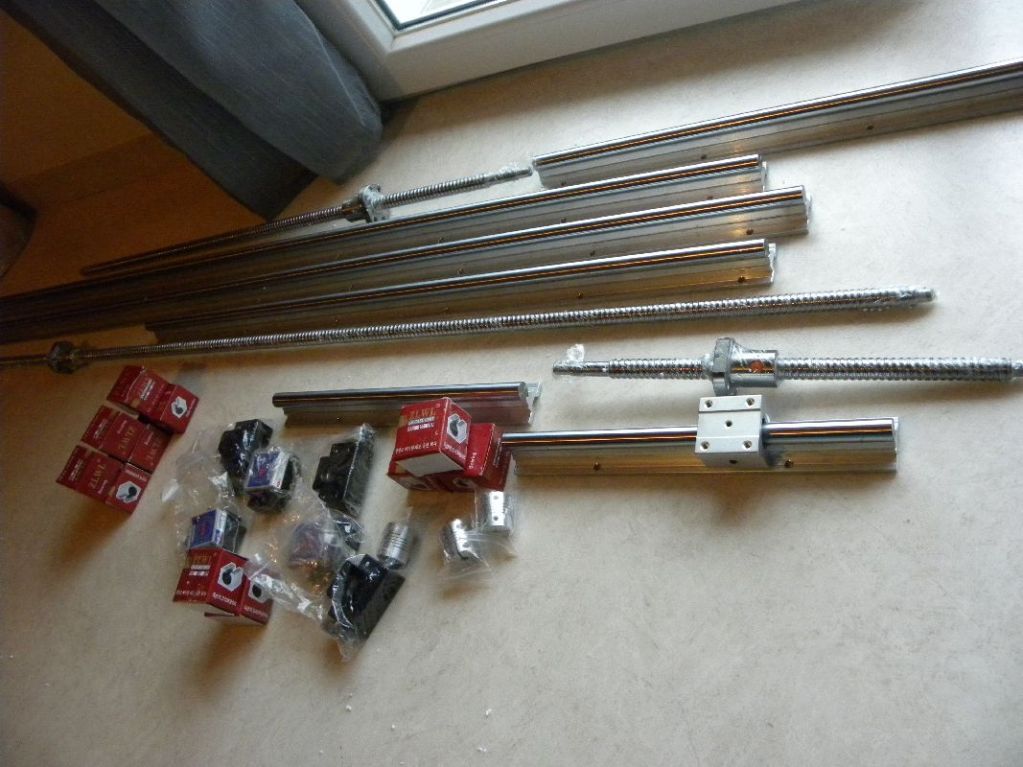
& finally a little disappointment
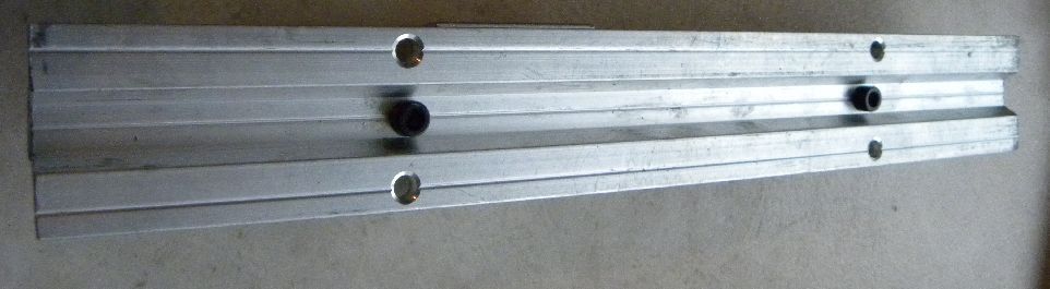
Not as brend new as announced or is it me? But everything seems clean.
Still need to check if they are alligned or not.
Sketch are being updated so I won't upload them yet.
Beside I have my first week of hollidays after a year of waiting so intend to enjoy them.
Z
-
07-11-2013, 09:17 PM #16
Registered
- Join Date
- Mar 2012
- Posts
- 16
UUUUUUUPPPPPPP
Hi there everyone project not dead, was just stopped temporarly.
I had a rought year with a lot of s*** to deal with and still haven't finish.
My project is still on the go even if it takes longer than I expect.
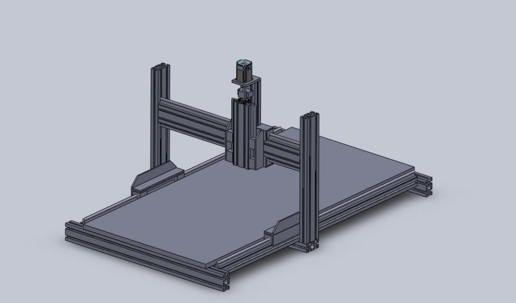
Just a quick update to show you the design I intend to make.
The cut of the aluminum are nearly finished, I should receive my stepper during the week.
If they aren't stop at the custom at least ....
Back
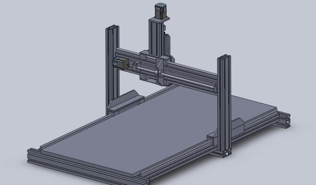
Fronft
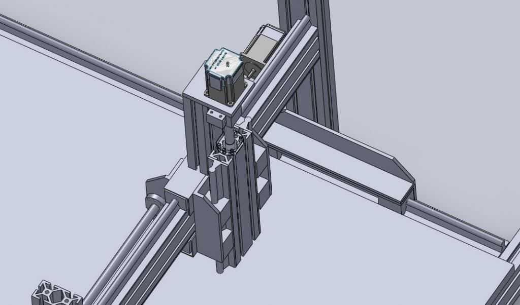
Carriage
-
08-05-2013, 11:26 AM #17
Registered
- Join Date
- Mar 2012
- Posts
- 16
Damn it not even a tiny comment ... Am I this boring ?
I know that my router has nothing fency or innovative but at this point ?
Whatever.
For those who take care (if there are some).
Quick update.
Parts are slowly getting together.
I also get the electronics and the motors.
The wiring is done and I've done few trial under Mach3.
I ordered a Kress router that is on its way.
Still got to order pulley and pinion and to find a way to assemble them.
A friend should also mill my rods 'cause they are a bit to long to fit my machine.
That's it for today.
-
08-08-2013, 09:45 AM #18
Registered
- Join Date
- Mar 2012
- Posts
- 16
Question for G540 users,
It seems that my G540 never turns faulty.
My wiring has been verified, nothing wrong.
The carge pump button of the G540 is set to OFF.
My // cable is OK.
Thought when I turn my enable switch off the G540 stays enlighten green instead of red.
Mach3 give me an error, will post a screenshot asap.
Thanks for any advice, I'm a bit lost right know, don't know how to solve this.
Z
-
11-30-2014, 10:26 AM #19
Registered
- Join Date
- Mar 2012
- Posts
- 16
Re: New build (I hope so) in France
Hi all,
undiging my topic once more.
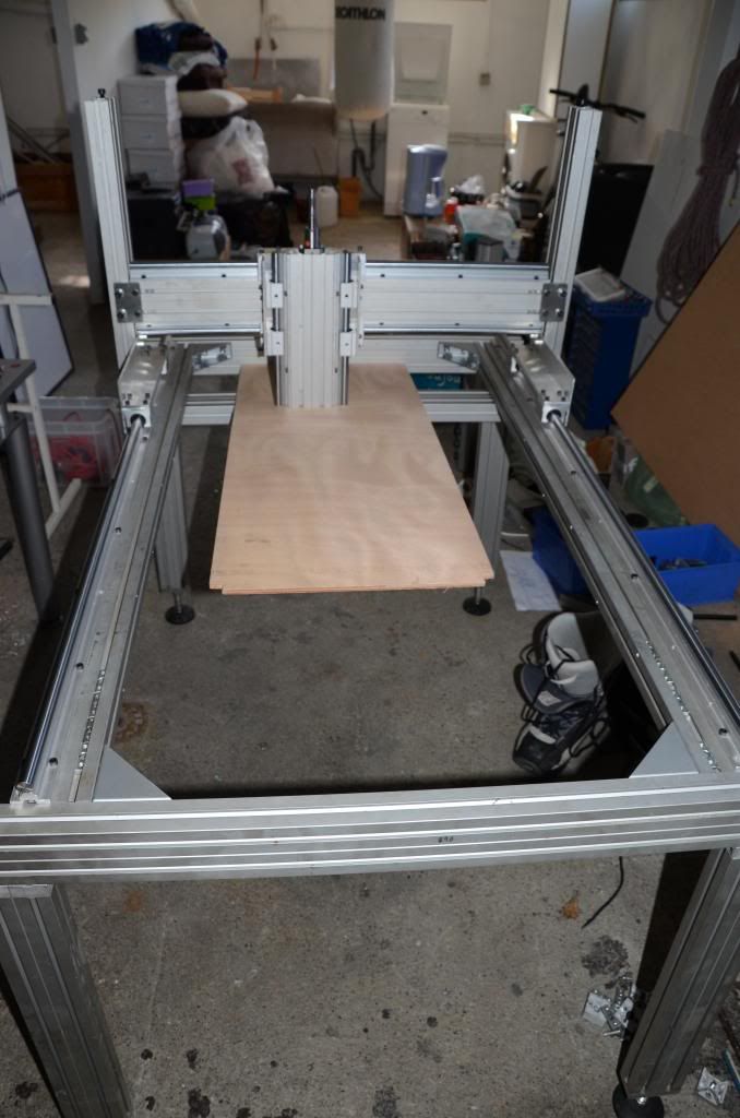
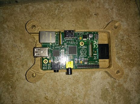
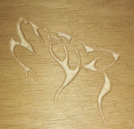
Up & running, I start few trial.
Raspi casing atempt
Wolf's head engraving
Ordered some mill bits and carving bits.
Quick off topic sharing : Open CNCed furnitures.
-
12-01-2014, 06:22 PM #20
Gold Member
- Join Date
- May 2005
- Posts
- 3920
Re: New build (I hope so) in France
You do realize that we, at least I, can't see your pics?
It is pretty hard to comment on what we can't see.

 Reply With Quote


Similar Threads
-
Hello from france
By VERICUT in forum Community Club HouseReplies: 1Last Post: 06-22-2013, 11:26 PM -
Hello from France
By gerard06190 in forum European Club HouseReplies: 4Last Post: 02-16-2011, 11:27 PM -
Hello everyone! from France!
By porcaro2 in forum European Club HouseReplies: 3Last Post: 10-21-2010, 11:45 PM -
Hello from France
By pimps in forum European Club HouseReplies: 2Last Post: 07-08-2010, 12:28 PM
