


Hello all, I am starting a project...putting motors onto my manual router table. I am going to use a hobby cnc driver and someone gave me a transformer to use but I can't find any information on it and am wondering if it is going to work. I will post links to some pictures of it...or maybe put them here if I can figure out how to do that!
Thanks,
Dave
Oh yea, I am doing three motors probably under 200 oz.
Thread: transformer for power supply?
Results 1 to 20 of 24
-
04-16-2012, 04:22 AM #1
 Registered

- Join Date
- Aug 2007
- Posts
- 69
transformer for power supply?
http://metalshop.homestead.com
-
04-16-2012, 03:24 PM #2
Community Moderator
- Join Date
- Dec 2003
- Posts
- 24221
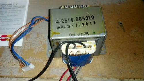
First you need to find the primary winding, probably the two black wires, the winding should be the innermost one.
Do a continuity test to see which windings are connected or separate from each other.
Apply 120v to it and check the voltage on all the other windings.
The VA rating of the transformer is basically a result of total core size of the transformer and the current capability of the windings.
Al.CNC, Mechatronics Integration and Custom Machine Design
“Logic will get you from A to B. Imagination will take you everywhere.”
Albert E.
-
04-18-2012, 05:55 PM #3
Registered
- Join Date
- Aug 2007
- Posts
- 69
Thanks for that. Is there a way to measure what the amps are on this transformer?
Davehttp://metalshop.homestead.com
-
04-18-2012, 06:20 PM #4
Community Moderator
- Join Date
- Dec 2003
- Posts
- 24221
No definitive means, you can generally go by the physical size to get an idea of the VA.
Al.CNC, Mechatronics Integration and Custom Machine Design
“Logic will get you from A to B. Imagination will take you everywhere.”
Albert E.
-
04-18-2012, 09:41 PM #5
Member
- Join Date
- Mar 2009
- Posts
- 533
To further what Al said, the VA is also related to the temperature rise of the transformer. This has to do with the maximum internal core temperature.
One could arrive at a reasonable current rating based on the maximum core temperature, but this would assume one has the proper equipment and transformer knowledge to make a test setup.
-
04-20-2012, 03:30 AM #6
Registered
- Join Date
- Aug 2007
- Posts
- 69
OK, I think I got my power supply up and running. This transformer actually had 5 secondary coils. the voltages were:
3.7
9.3
12.0
18.9
35.4
I went with the 18.9 and after running it through the capacitors, it came out to 25.1 Volts.
The store where I got my capacitors didn't have too much selection so I put two 4700 uF capacitors together. That was the largest they had...I feel like I should have gone with three though??
Here is a picture of what I set up:
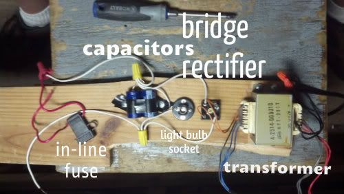
Oh yea...one other question. I decided to try it out immediately so I hooked it up to my 24 volt computer cooling fan. It instantly fried it. Think that shows something wrong with my setup, or are their tolerances that tight...or maybe I shouldn't have had the two wires together...I have run that fan on 12 volts before?
I am afraid I know just enough electric to get me in trouble!
Davehttp://metalshop.homestead.com
-
04-20-2012, 04:30 AM #7
Community Moderator
- Join Date
- Dec 2003
- Posts
- 24221
Computer fans are usually 12vdc, if ran off the PC P.S.?
Al.CNC, Mechatronics Integration and Custom Machine Design
“Logic will get you from A to B. Imagination will take you everywhere.”
Albert E.
-
04-20-2012, 04:49 AM #8
Registered
- Join Date
- Aug 2007
- Posts
- 69
well, it said 24 vdc on it...so I thought one more volt wouldn't hurt it! I am not sure where it came from...
http://metalshop.homestead.com
-
04-20-2012, 09:23 PM #9
Member
- Join Date
- Mar 2009
- Posts
- 533
I couldn't fully follow your transformer wiring.
From your photo I count 9 secondary wires (some hidden?);
2 blue, 2 grey, 2 red, 2 brown and one black, and two primary wires - black.
You list 7 secondary voltages.
Any of the wires a center tap?
Are all secondary wires the same wire gauge?
Any idea which equipment the transformer might have come from?
-
04-21-2012, 12:30 AM #10
Registered
- Join Date
- Aug 2007
- Posts
- 69
Sorry about that...the 25.1 I had listed there was the final voltage...so I edited the post. Yes all the secondary wires are the same gauge. The black one formed a circuit with the orange ones...does that mean it is a center tap?
I believe it came out of a stereo system.
Dave Dhttp://metalshop.homestead.com
-
04-21-2012, 12:55 AM #11
Community Moderator
- Join Date
- Dec 2003
- Posts
- 24221
Measure the AC between the ones that have continuity and you can tell the centre taps from this. Originally Posted by drescher3

Al.CNC, Mechatronics Integration and Custom Machine Design
“Logic will get you from A to B. Imagination will take you everywhere.”
Albert E.
-
04-21-2012, 01:15 AM #12
Registered
- Join Date
- Aug 2007
- Posts
- 69

It was very late when I posted the transformer voltages
 I went back and edited them to be right! Here are the values before and after the rectifier and capacitors:
Grey-grey 3.7 4.4
orange-black 9.3 12.0
red-red 12.1 15.9
orange-orange 18.9 25.1
blue-blue 35.4 47.4
Dave Dhttp://metalshop.homestead.com
-
04-21-2012, 04:26 PM #13
Community Moderator
- Join Date
- Dec 2003
- Posts
- 24221
Keep in mind that usually with a multi-secondary Txmr the appropriate gauge of the winding conductors is spread across the total VA, so if you end up only using one winding, that winding may not necessarily be of sufficient gauge to carry the total max. current.
Al.CNC, Mechatronics Integration and Custom Machine Design
“Logic will get you from A to B. Imagination will take you everywhere.”
Albert E.
-
04-21-2012, 08:32 PM #14
Member
- Join Date
- Mar 2009
- Posts
- 533
OK, I missed the orange wire. You now have 5 pairs. But as Al said an "ohmic" check will verify if some of these wires are center taps.
If the transformer did come from a stereo, then I would guess that the main secondary power supply to be provided by the 35.4VAC windings. This one would provide the most power. - I know it is risky to guess.... I'm also assuming that it could provide 50 to 60 watts per channel. Just don't take these guesses to seriously.
-
04-21-2012, 09:55 PM #15
Registered
- Join Date
- Aug 2007
- Posts
- 69
Well my max voltage for my driver is 32 I believe so I am using the 24v leads. I am using a hobby cnc driver and the motors I am looking at are two amp...so I would be operating 3 motors max 6 amps plus whatever the driver uses...not much I think. I don't know how to know if the wire size is enough or not...I guess the worst that could happen would be that the wires would get hot and melt though.?
Davehttp://metalshop.homestead.com
-
04-21-2012, 10:06 PM #16
Member
- Join Date
- Mar 2009
- Posts
- 533
That's what fuses are for, so your wires won't burn
-
04-21-2012, 10:23 PM #17
Community Moderator
- Join Date
- Dec 2003
- Posts
- 24221
18 gauge is around 7 amps.
So you may be could get an idea from that, if you can see the exposed winding.
Al.CNC, Mechatronics Integration and Custom Machine Design
“Logic will get you from A to B. Imagination will take you everywhere.”
Albert E.
-
04-22-2012, 03:45 AM #18
Registered
- Join Date
- Aug 2007
- Posts
- 69
Is it possible to use two of the secondary windings in the same circuit? Like if I added the grey-grey, would it add 4.4 volts to the total...and help share the load? Originally Posted by Al_The_Man
As you can see, i don't know much electric theory!
Davehttp://metalshop.homestead.com
-
04-22-2012, 03:47 PM #19
Community Moderator
- Join Date
- Dec 2003
- Posts
- 24221
Yes, you can put two windings in series, if the result is reduced by 4.4v then swap any pair, if you were paralleling equal windings they would have to be phased first before connecting.
Al.CNC, Mechatronics Integration and Custom Machine Design
“Logic will get you from A to B. Imagination will take you everywhere.”
Albert E.
-
04-22-2012, 04:04 PM #20
Registered
- Join Date
- Aug 2007
- Posts
- 69
But would that help with the load? It seems to me that all the current would still be going through one path so it wouldn't make any difference...unless the higher voltage would lower the amps?
Thanks for this thread by the way...I am learning a lot.
Dave
Originally Posted by Al_The_Man
http://metalshop.homestead.com

 Reply With Quote
Similar Threads
-
Microwave transformer built power supply
By TinkerDJ in forum CNC Machine Related ElectronicsReplies: 66Last Post: 04-30-2021, 02:57 PM -
Transformer for servo motor power supply
By robhrzic in forum Servo Motors / DrivesReplies: 3Last Post: 06-12-2020, 09:49 AM -
Ferroresonant transformer for power supply?
By DennisCNC in forum CNC Machine Related ElectronicsReplies: 3Last Post: 09-04-2012, 04:22 PM -
Power Supply Transformer Question
By snooper in forum CNC Machine Related ElectronicsReplies: 4Last Post: 07-30-2006, 10:38 AM -
control transformer to power supply?
By bobleecnc in forum CNC Machine Related ElectronicsReplies: 8Last Post: 05-20-2006, 02:42 AM
