


Im converting (yet another) LMS mini mill to CNC. Trying to, at least. Im very new to this and having trouble finding a diagram on how to wire these digital drivers to the BOB. Im not sure why, but I thought I just be able to look it up and move forward. This hasnt been the case, and im worried I might screw something up and fry a driver/motor or something. Any help from you gurus would be much appreciated!
This is the kit I have:
eBay - New & used electronics, cars, apparel, collectibles, sporting goods & more at low prices
I came across this, but it didnt help:
CNC breakout board: DB-25 and DB-9 pin assignment
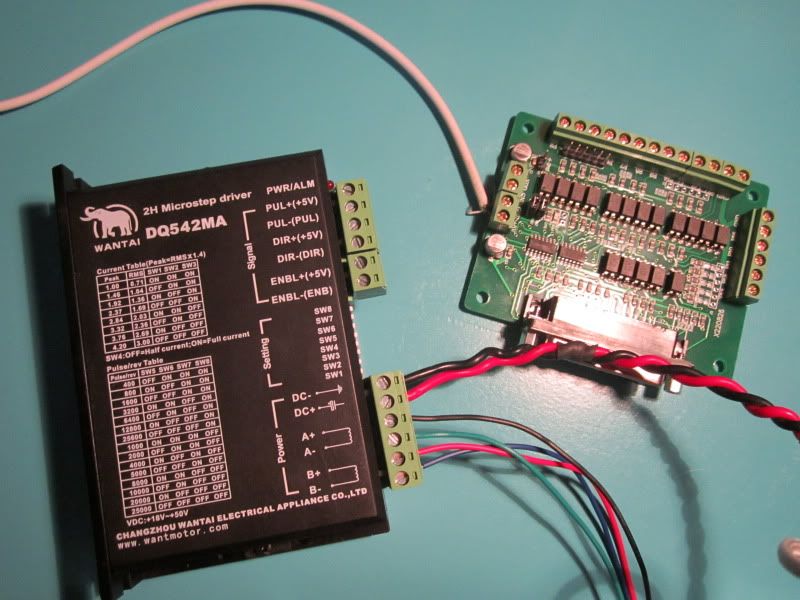
Here's where I am now. The power supply is 48V.
Thread: Wiring digital driver to BOB?
Results 1 to 20 of 72
-
04-25-2012, 04:39 AM #1
 Registered
- Join Date
- Sep 2011
- Posts
- 474
Wiring digital driver to BOB?
-
04-25-2012, 05:02 AM #2
Gold Member
- Join Date
- Feb 2006
- Posts
- 7063
Connect your BOB Step output to PUL+, DIR output to DIR+, ENABLE to ENA+. PUL-, DIR-, ENA- all go to BOB Ground. If you don't have an ENABLE output, you can leave ENA+/ENA- not connected.
Regards,
Ray L.
-
04-25-2012, 05:09 AM #3
Registered
- Join Date
- Sep 2011
- Posts
- 474
Alrighty, so which is the step output? The DIR output? Originally Posted by HimyKabibble

Edit: Here's a good shot of the board:
http://www.cnczone.com/forums/attach...2&d=1299105524
-
04-25-2012, 05:25 AM #4
Registered
- Join Date
- Aug 2010
- Posts
- 0
One concern I see is that the current specifications of the motor (4.2 Amps)
"Part No.: WT57STH115-4204A single shaft
Frame Size: NEMA23
Step Angle: 1.8 degree
Voltage: 3.78VDC
Current: 4.2 A/phase
Resistance: 0.9 Ohm/phase"
exceed the specifications of the driver's current.
"...VDC. It is designed for use with 2-phase hybrid stepper motor of all kinds with 42mm to 86mm outside diameter and less than 4.0A phase current. This circuit..."
It will probably work, but would worry me. I like a little more wiggle room. Joe
-
04-25-2012, 05:43 AM #5
Gold Member
- Join Date
- Feb 2006
- Posts
- 7063
Which BOB output is used for which function is determined by how YOU configure Mach3. And since that BOB does not seem label many of the terminals, I can't help you with that. I assume that top row is pins 2-9, with grounds between each pair, but no way to know for sure. That's the problem with buying Brand X Chinese parts.... You'll have to contact the seller and ask them. Originally Posted by SwampDonkey
Regards,
Ray L.
-
04-25-2012, 05:44 AM #6
Registered
- Join Date
- Sep 2011
- Posts
- 474
Originally Posted by toughtool
I thought the same thing and mentioned it in an email to them before buying. They said it was likely a mistake, and the "42" in the DQ542MA designation denotes 4.2A. Livin on the edge!
I came across this on the Yahoo group. Its how another guy wired his identical BOB:
Im thinking he omitted quite a bit as he leaves out the ground wiring.Stepper controllers are wired to breakout board as below.
X =
P2 Puls (-)
P3 Dir (-)
Y =
P4 Puls (-)
P5 Dir (-)
-
04-25-2012, 05:45 AM #7
Gold Member
- Join Date
- Feb 2006
- Posts
- 7063
That's not a problem at all. He just has to set the current limit to 4A, and he'll be getting slightly less than rated torque from the motors. There is NO risk to the drivers at all. Originally Posted by toughtool
Regards,
Ray L.
-
04-25-2012, 05:48 AM #8
Registered
- Join Date
- Aug 2010
- Posts
- 0
swampdonkey
,
When running a job, the computer outputs a series of pulses for each motor, one for direction (forward or reverse, called DIR), and one for steps, to rotate the motor so many steps. If you want the X axis to travel 100 units in the positive direction, the DIR = +, and STEP will get 100 pulses to turn the X axis motor 100 steps. Travel distance will be determined by the pitch of a leadscrew or ratio for a gear/belt or gear driven rack and pinion system. The "G" code commands [lines] contain the information as to which motor, how many steps, and what direction the motor needs to be turned. Like basic programming, each "G" code line is executed in order, unless sent to a different (like a subroutine) line. The other inputs and outputs (i.e. ENA+) are sensing inputs for limit and or emergency stop switch devices and other things. Joe
-
04-25-2012, 06:06 AM #9
Registered
- Join Date
- Aug 2010
- Posts
- 0
Ray, It would be my luck to turn it on and it already be set for full current and smoke it before I could adjust it. I'm running old IBM unipolar motors so I built my own drivers using a MOSFET that can handle 45 amps, driven with a CMOS gate. I even manged to smoke one of them once, but at $1.50 each, wasn't much of a problem. I use a current limiting resistor for each winding and not driving them with pulses to regulate the current. Can't tell any temperature change from off to full current after fifteen minutes. So no heatsinks needed. the DQ542MA unit does look simple and small. Joe
-
04-25-2012, 02:07 PM #10
Registered
- Join Date
- Sep 2011
- Posts
- 474
Thanks for the info. I set up mach 3 according to the tutorial (assigned pins and such) and now the motor will turn when jogged....in one direction. I can hit the x+ and x- buttons and it spins in the same direction regardless. Once again, im stumped. I tried different pin combinations and it doesnt work at all. Could the e-stop have something to do with this? I saw iy mentioned while doing research on the problem but they didnt go into much detail. Thanks! Originally Posted by toughtool
-
04-25-2012, 05:46 PM #11
Gold Member
- Join Date
- Jan 2010
- Posts
- 2141
Originally Posted by SwampDonkey
There are (at least) two ways to hook up the breakout board to the driver.
The way that was recommended earlier will work if your breakout board outputs can source enough current to drive the LEDs in the driver's input circuit.
Some breakout boards do better at sinking current than at sourcing current. The description that you quoted from the Yahoo group sounds like that user has wired up the breakout board to sink the driver's optoisolator currents, which is why the hookup is to the minus (-) puls and dir terminals. In such a hookup, the puls+ and dir+ terminals would be connected to a positive voltage (such as +5 volts). [similar for enable, or leave enable disconnected]
As for your problem with the axis going in the same direction no matter which direction you jog it, some of the most likely causes would be either incorrectly configuring the axis direction pin in Mach3, or using the wrong cable between the PC and the breakout board, or a bad connection to the dir terminal on the breakout board (or the wrong terminal chosen on the breakout board, or an incorrect jumper setting on the breakout board).
It is unlikely that the E-stop would have anything to do with that symptom, because Mach3 should not be sending step pulses to the driver if the E-stop has been tripped.
One more note - it looks like your breakout board has built-in optoisolators, which means that you will be driving the optoisolators in your drivers through the optoisolators in your breakout board. That is generally a "bad idea" - you might want to get a different breakout board.
-
04-25-2012, 07:51 PM #12
Registered
- Join Date
- Sep 2011
- Posts
- 474
Ah, thanks. I'll look into getting a new board as well. Others have had this exact set up working and I'd like to get a sort of proof-of-concept to plan out the wire routing. Originally Posted by doorknob
Currently I have:
Step Pin at p2
Dir Pin at p3
P2 to PUL-(PUL)
P3 to DIR-(DIR)
And 5V+ connected to PUL+ (+5V)
DIR+(+5V)
ENBL+(+5V)
I also have both "LowActive" buttons clicked on this axis.
The motor still turns very slowly in one direction.
-
04-25-2012, 08:40 PM #13
Gold Member
- Join Date
- Jan 2010
- Posts
- 2141
Check the voltage (with a multimeter) between Dir- and board ground.
It should be "high" when jogging in one direction, and "low" when jogging in the other direction. What are the exact voltage readings that you see for each direction?
If no change is noticed, the first thing that I would check would be the cable from the parallel port to the breakout board. Do all pins go "straight through"? Can you see the voltage on pin 3 of the cable change when you change jogging directions?
-
04-27-2012, 10:49 PM #14
Registered
- Join Date
- Jun 2011
- Posts
- 0
Hi there again SwampDonkey have a look here at this guy's series of CNC electronics he has 9 videos in his series [ame=http://www.youtube.com/watch?v=Lu0eNoP0zIg&feature=relmfu]CNC Electronics 4 - Mounting the Breakout board.wmv - YouTube[/ame] but one thing to not do is daisy chain the power to the drivers, other than that it's a good basis for reference....
Eoin
-
04-30-2012, 03:31 AM #15
Registered
- Join Date
- Sep 2011
- Posts
- 474
Ah, thanks. I think ive got it for the most part. Figuring out Mach 3 is on my plate for now. The steppers are moving VERY slowly but working. Ive toyed with the acceleration and IPM settings but they still move in slow motion. they also get really hot when left on for a while. Im sure ive got something wrong but need to hunt it down. Originally Posted by Mad Welder
-
04-30-2012, 12:16 PM #16
Registered
- Join Date
- Jun 2011
- Posts
- 0
Have your drivers got a dip switch to set to half power when not moving? Originally Posted by SwampDonkey
the keling drivers I have, also have that feature..!http://www.kelinginc.com/KL-8056D.pdf check out page 6 in the manual...Eoin
-
05-01-2012, 12:17 AM #17
Registered
- Join Date
- Sep 2011
- Posts
- 474
Nope, not that I can find. Are the motors supposed to get hot enough to burn your hand? Also, the motors are very slow. Much slower than ive seen others running. Ijust turned mach 3 back on and now it refuses to run without an e-stop. Any way for me to get it to ignore this? It did before but apparently changed its mind. The steppers are not on the machine, I just want to get them working before taking that step. Originally Posted by Mad Welder
Edit: Weird stuff happening here. It turned the e-stop requirement back on and changed the stepper output ports on me. I was just messing with it last night and am sure they were set up correctly, now they're different. Any reason this would happen?
-
05-01-2012, 12:24 AM #18
Gold Member

- Join Date
- Nov 2009
- Posts
- 4415
Hit the "Tab" key. There will be an MPG flyout. Within that flyout there will be a % of speed setting. What happens if you hit "shift" and the directional hotkey? Does it go much faster?
-
05-01-2012, 12:26 AM #19
Gold Member
- Join Date
- Nov 2009
- Posts
- 4415
Steppers do get hot. They shouldnt be hot enough to burn your hand however their heat can startle you. Are they really that hot? Uncomfortable for sure. If they are really hot, your amperage setting on your driver is too high.
-
05-01-2012, 12:30 AM #20
Registered
- Join Date
- Sep 2011
- Posts
- 474
Yeah, thats what ive been using to test the motors. No, the very fastest it will go is still painfully slow. Originally Posted by Fastest1

 Reply With Quote
Similar Threads
-
Digital tool dr902 wiring diagram
By brockadeau in forum BobCad-CamReplies: 2Last Post: 10-20-2014, 01:51 PM -
Keling Digital driver problems
By 996pilot in forum Stepper Motors / DrivesReplies: 8Last Post: 01-12-2013, 12:25 AM -
digital stepper driver recommendations
By dsnaith in forum Stepper Motors / DrivesReplies: 0Last Post: 11-30-2012, 10:50 PM -
Digital Stepper Driver
By kolias in forum Open Source CNC Machine DesignsReplies: 2Last Post: 03-08-2012, 02:03 PM -
Can you pulse a digital driver manually?
By Fastest1 in forum Stepper Motors / DrivesReplies: 5Last Post: 08-18-2011, 06:35 AM
