


Well I am almost done with the rebuild on my VF-1. I went out to the shop today with the intentions of loading the program, setting up the stock and giving it a dry run. After powering it up, homing it and a few movements I noticed the characteristic electrical burning smell. I quickly shut it down and open the rear door only to have smoke come billowing out at me! :bawling: After the smoke clears I get a chance to see what happened. Apparently the two spindle brake resistors got red hot and started to burn everything near to themselves. The servo resistor in between the two did not get hot. I let it cool off and powered it up again. The resistors immediately start to heat up. I shut it down again. I noticed that the drive had an error code E6E on the display, "Brake transistor fault detection." As far as I can tell, only the resistors are ruined and some wiring, so far. The wire looms are shot in a few places but they will serve their purpose "as is" for now. I Googled the drive and problem but came up with nothing.
Here is the information that I have gathered so far to try and diagnose what happened. The only work I have recently done to the mill was I put a rectifier bridge in to convert to AC voltage for the light to DC to run my new LED lights. If I unplug the LED and the rectifier the resistors still get hot at start up so I don't think that caused it, I hope. After I powered it up I homed it, moved it back to center of its travels, then homed it again. The auto power up is slow to home but the second time I homed it was at rapids. I think this may have been the point that something failed but I don't know. Also I got no over-temp alarms even thought the temp sensors got so hot they melted! The drive lists an input of 230v at 60 hz on the front panel. I am getting 244, 243, 242 from my phase converter while loaded. I am dead on 60 Hz as well. The drive is a Mitsubishi Freqrol-Z300 model# FR-Z320-3.7K.
I am so close to making parts that this makes me sick to my stomach!:vomit:
Anyone out there have any advise?
Steve
PS. I am so ticked about this I have managed to consume 3 beers while writing this, benefits of a home shop and being able to call it a day whenever.
Thread: VF-1 Almost caught on fire!!!
Results 1 to 14 of 14
-
05-29-2012, 12:38 AM #1
 Registered
- Join Date
- Sep 2011
- Posts
- 77
VF-1 Almost caught on fire!!!
-
05-29-2012, 12:49 PM #2
Registered
- Join Date
- Apr 2005
- Posts
- 1268
Wow Steve, sorry to hear about the problems. I've followed your re-build thread from the beginning and you did a great job. By chance, is there a break circuit schematic available than you can post? Sound like a shorted component of some sort. I know this is not much help but maybe someone will have one to post and help out!
Good luck and I look forward to seeing some great parts come out of your machine.
Billbillyjack
Helicopter def. = Bunch of spare parts flying in close formation! USAF 1974 ;>)
-
05-29-2012, 04:19 PM #3
Registered
- Join Date
- Feb 2010
- Posts
- 1184
Very frustrating I am sure.
First off, homing the second time was faster because the machine already knew where it was at; this is normal.
Some things to try.
Make sure the transformer taps in the machine cabinet are set to the proper voltage range for incoming power.
Next, disconnect the leads going to the spindle motor at the spindle drive. See if you can zero the machine, 1 axis at a time, without any problems.
If that works ok, double check the wiring connections to the spindle motor and if you have access to a megohm meter, check the motor and cable for any shorts.
You might want to make sure the resistors still read the correct amount of resistance, sorry I couldn't tell you what they should be though.
Hopefully you did not let all the smoke out of the machine and you can track the problem down. (flame2) (sorry could't help myself)
Good luck!!
-
05-29-2012, 04:46 PM #4
Gold Member
- Join Date
- Feb 2009
- Posts
- 6028
Posted on you other post,
But you have a brake transistor error on the drive. Im guessing you have a bad brake transistor in the drive, dumping current in to the regen resistors when not braking the spindle. Ive seen this before on older equipment. Makes a mess for sure.
-
05-31-2012, 04:03 AM #5
Registered
- Join Date
- Sep 2011
- Posts
- 77
I do not have a transformer in my machine. The input power goes directly into the main breaker and from there to contactors and the rest of the machine. What can I do to get the voltage down to 230? Originally Posted by haastec

Thanks for the help. :cheers: The first thing I did was to make sure that the motor leads were the correct resistance against themselves and test for short to ground. Everything checked out good so I decided to open up the drive. Originally Posted by haastec
I also had my suspicions on the transistor so here is what I did next. Originally Posted by underthetire
OK, so I refuse to give up so I took apart the drive to see if whatever went bad could be easily replaced. First I followed the wires to the rear board and from there traced out where the related components were located on the board that controlled the brakes. I found a relay, a few large resistors, a few smaller components and a large transistor. I know that the most likely cause for the short was the transistor so I removed it from the board to test it and sure enough, it is shorted across the collector and emitter, actually about .3 ohms. A am pretty sure it should be open under normal circumstances.
What I am up against now if finding a suitable replacement transistor and figuring out why it went bad in the first place and if it took out anything else when it went.


The transistor is a Mitsubishi QM10HA-HB

I have found one small resistor so far that seems to have gone to. I am also going to replace the capacitor while I am in there but I have not tried to source it yet. The big blue cap in the picture above.
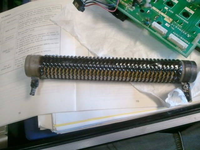
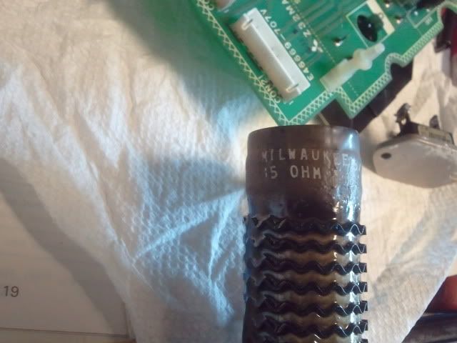
I also need to source 2 new regen resistors. They are Milwaukee resistors, labeled 15 ohm. Haas tech support says that they should be 10 ohm and the servo resistor should be 25 ohm but I have 2 15' s and one 50. Any ideas?
Steve
-
06-09-2012, 04:25 PM #6
Registered
- Join Date
- Sep 2011
- Posts
- 77
Well, here is where I am at so far;
Well I do have two buck/boost transformers on my machine. I just did not know what they were until all of this happened and I started to look for a way to get the voltage down. I still have to check to see how they are wired. They may be boosting the already too high voltage to an even higher voltage. That would at least explain what happened to the drive. Some lessons are learned the hard way I guess. Originally Posted by AutoTechSteve
 I'll post what I find after I get a chance to get into it.
On to the repair part:
I have called and talked to Milwaukee resistor and I can get new braking resistors from them. I have come across newer style enclosed resistors on the web but I am unsure as whether to go with new style or stick to the old. They are 300 Watt and 15 Ohm wire wound resistors. I ordered the transistor from a supplier in China so I have got about two weeks before I get them. As soon as they show up I will get one installed. I ordered two, just in case. They were $6 each but the shipping was $18 so why not. I am also going to go through the braking circuit on the board and testing the other components on it so that I can replace what is bad or out of spec. Lucky for me there is not much else in the circuit and it is all local stuff and easy to get. I am also going to have to replace the temp sensor harness as well, which Haas can get for $28 but I also need to replace the wire "loom" that the harness is routed in. I am not sure what to call it so I have had a hard time finding a replacement. Any help out there? I am referring to the grey "toothed" loom that all of the wires are run inside in the cabinet. Thanks again everyone for the help and I will update when I get parts in.
Steve
-
06-10-2012, 07:09 PM #7
Registered
- Join Date
- Sep 2011
- Posts
- 77
As for the wire duct I found some of what I need at McMaster Carr and they are about 30 minutes from me so I can pick some up on Monday.
I checked the output voltages from my Busk Boost transformers and they are set to output 230 from a 240 input. I fired up the phase converter and checked the voltages at the input contactor in the cabinet and sure enough they are at 230, 232, 234. I don't know what the heck happened to the drive transistor. Hopefully it was just a fluke or age and I can get it fixed and not have to worry about it again. All of the drive re-builders I talked to tend to say that this sort of problem is very common and they see it quite often. I guess I will find out when the transistors get here.
Steve
-
06-17-2012, 08:02 PM #8
Registered
- Join Date
- Sep 2011
- Posts
- 77
Transistor came in from Singapore yesterday and I am getting ready to install them. I am trying to go through the rest of the board to make sure that nothing else was damaged when the transistor shorted out. I have two questions that I thought all of you can help me out with. Below is a picture of a component that I cannot identify. I am not sure what it is but I would like to be able to test it before I reinstall it.

So far I also need to get the regin resistors in the mail and the two harnesses that melted in from Haas. I need to get this thing up and running. It never fails, machine quits and orders start coming in. :angry:
Last thing I wanted to run past everyone. The only changes I made to the mill the night before this happened was that I added LED lights to the inside and I installed a small diode bridge in the cabinet inline to the lights to convert the 12VAC to 11.3VDC. I doubt that adding a rectifier bridge to the light circuit could have caused the drive to fail but I wanted to see if any of you guys had any input. I know that when I do get the mill up and running again I am going to leave that lights unplugged. That way if things go well with the lights unplugged and for some chance when I plug them back in the drive messes up again I will know why.
Steve
-
06-17-2012, 08:53 PM #9
Community Moderator
- Join Date
- Dec 2003
- Posts
- 24221
Just a shot in the dark, but I would say it is a polarized suppression of some kind, probably a rectifier capacitor network.
The minimum test would be a meter on diode scale and check for forward conduction only.
Open in reverse?
Al.CNC, Mechatronics Integration and Custom Machine Design
“Logic will get you from A to B. Imagination will take you everywhere.”
Albert E.
-
06-30-2012, 04:34 AM #10
Registered
- Join Date
- Sep 2011
- Posts
- 77
Well I got the new transistor in a soldered it back to the drive board, made up some new cables to replaced 3 of them that were burned and voila!, it fired up and so far seems to be functioning normally.
To be honest, I am shocked that it was only the transistor that went and not something else. I am going to go ahead and order a new capacitor for the drive, from what I have heard that is an item that needs to be replaced every so often. Maybe someone can comment on that. Regardless, I am still happy as you know what!
Steve
-
06-30-2012, 04:41 AM #11
Gold Member
- Join Date
- Jun 2011
- Posts
- 695
Great news!
Awesome that worked out for you...chipsAflying!
-
07-01-2012, 02:37 AM #12
Registered
- Join Date
- Sep 2011
- Posts
- 77
Well I spoke to soon I guess. :cryin: I ran it yesterday for an hour or so trying to program it and I did not have any problems with the resistors getting hot. I thought everything was OK until about 10 minutes ago. I went out to change a few lines of code and realized that a lot of the code was not sent properly from my laptop so I shut it down. Just to check I opened the cabinet and sure enough the resistors were glowing red. At least I caught it this time before anything was damaged like last time. I know that the transistor is probably to blame again but what could cause it to fail? I am wondering if it is something outside the spindle drive that is causing it.
Here is what I have so far to this point;
1. The resistors themselves are new so I am sure it is not them.
2. The last time I checked DC voltage was right but I am sure it would alarm if it were too high or too low.
3. It sets an alarm every once in a while for spindle orientation. It will run the spindle and activate the orientation pin, I can hear the pin drop and the spindle will stop turning but when it happens the spindle load goes to about 50% and it hangs at 50% for a few seconds and then pulls the orient pin and it try's to orient again. It has done this to me before and when I had the mill apart I checked the pin drop limit switch and it checked OK so I did not think anything about it.
4. A possible voltage spike in the braking circuit could cause the failure. The transistor is rated for 600v and 30amps so it would have to be high. I did not run the spindle at all tonight or yesterday after the initial repair other than the spindle orient so a voltage spike would not be from actual braking of the spindle.
5. I also came across capacitors causing transistor failure. Here is an excerpt of what I found
"Transistor failure is often caused by bad capacitors. It is extremely
common to find output filter capacitors that are swollen or leaking. Any
capacitor that appears to be bad should be replaced. To prevent a
recurrence of this all-to-common failure, output filter capacitors should
be replaced with special "low ESR" (Equivalent Series Resistance)
capacitors. These capacitors are specifically designed to handle the
rigors of filtering in a switching supply. Most power supply
manufacturers do not install low ESR capacitors as original equipment
because they are somewhat more expensive that conventional capacitors.
However, it is well worth the money to use them as replacement components
as they will greatly extend the life of the power supply in the field.
When I work on a power supply, I replace all the output filter capacitors
with low ESR caps regardless of whether they appear to be good or bad.
Since a service call costs far more than the capacitors, it's a prudent
thing to do."
There are a few capacitors in the system. One inside the drive itself, and a few in the cabinet, I assume to smooth AC to DC. I heard that it is good maintenance to change the capacitor in the drive. I don't have a way to test it because of its size.
Hopefully someone out there can help. I am trying to start a business with this mill and my one customer waiting on his parts.
Steve
-
07-01-2012, 03:04 AM #13
Registered
- Join Date
- May 2012
- Posts
- 0
vf1
the vf1 has a coolant hose running in the wire tracks going to the spindle. often the line leaks inside of the conduit leaking coolant on to the power supply and servo drives. i recommend inspecting for this and if you find it move the hose out of the loom. if you dont have a problem i would still move the hose as it will destroy your power supply when it fails. also the leak generally starts small and gets worse
-
07-30-2012, 05:07 AM #14
Registered
- Join Date
- Sep 2011
- Posts
- 77
Thanks for the tip, I am going to check for it but I have been busy with this project. Originally Posted by jcyonngs76
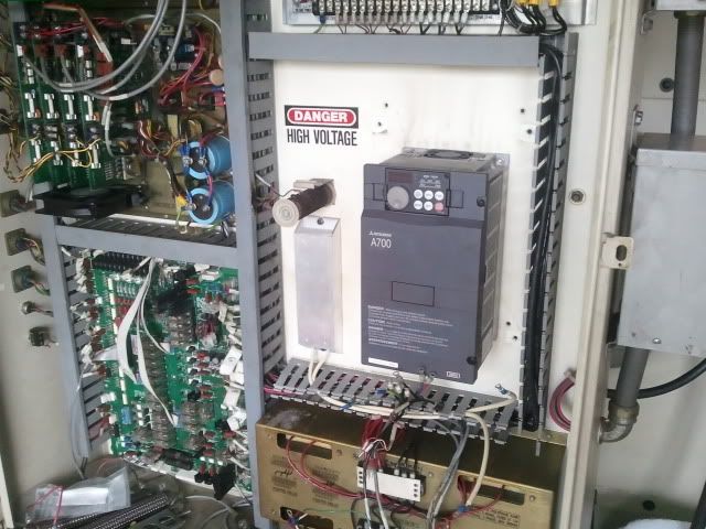
Well long story short, I had Mitsubishi on the phone about the old drive and I asked about a cross reference to a new drive. Turns out its about half the cost to update to a new drive rather than try to rebuild the old one. So know I am in the process of updating the Z300 to an A700. Below are my install notes and connection notes. Let me know what you think about how I connected it and set it up. This post is also for anyone who needs a good start if they plan on doing the same swap. Enjoy
Old drive;
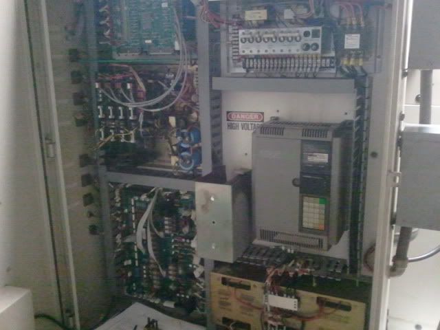
New drive;
Z300_____________________________________________A 700
Daughter Board Connections;_________________________No need for the daughter board on the A700, analog output is built in as terminal AM and the common is terminal 5
LM0- 730 and 731B_________________________________AM- 730 and 731B
LM2- 730 and 732B_________________________________5- 730, 732B
Main Unit connections;
B- 781___________________________________________B1- 781
C- 782, Jumper to SE_______________________________C1- 782 (not sure about jumper to SE)
SD- 502, 401, 714, Jumper to SE_____________________SD- 502, 401, 714 (not sure about jumper to SE)
5- 722, Capacitor to 1K, Jumper to SE_________________5- 722, (not sure about jumper to SE or capacitor)
1K- 721, Capacitor to 5_____________________________1- 721, (not sure about capacitor to 5)
STF- 711_________________________________________STF- 711
STR- 712_________________________________________STR- 712
JOG- 501_________________________________________JOG- 501
RUN- 784_________________________________________RUN- 784
SU- 783__________________________________________SU- 783
FU- Jumper to RT__________________________________FU- Jumper to RT
RT- Jumper to FU__________________________________T- Jumper to FU
MRS- 402________________________________________MRS- 402
RES- 713_________________________________________RES- 713
Motor output and power input are as designed__________Motor output and power input are as designed
This is my notes, findings and info on changing the Mitsubishi Z300 series of drive to the A700 in my Haas VF-1 CNC mill. I will abbreviate parameter with Pr throughout this description.
To start with my Z300 was equipped with daughter board FR-ZLME. This board was set to output current with an analog signal to the load meter on the operator panel. This is done with parameters 72, 73 and 74. 74 to output current, 73 is the full-scale output and set to 33amps, 72 is set to 0 amps for the zero scale. This board is not necessary with the A700 because the analog output is built in as terminal AM and its common terminal 5. The settings in the parameters are set Pr158 to 2 for output current. Set Pr56 to 17 amps, the A700 will output 100% at the max set amps. This means the meter on the operators panel will be at 100% when the output amperage is at 17 amps, or the nameplate load on the motor. Pr 186 is for terminal AM response time and is set to 4ms when the Pr is set to 0. Be sure to calibrate the meter last using Pr901.
Now on to the main parameters;
Most of the parameters cross over to the new drive just as they are set in the old drive. Mitsubishi did a great job keeping their drives consistent even with a 20+ year span in age. All parameters are the same between the two drives except for the following;
Parameters 14, 17, 19, 21, 23, 59, 63, 64, 67, 75. I will go through each of the following in order;
Parameter 14;
Leave at the default setting, it may change during the auto-tune process.
Parameter 17;
Pr17 in the Z300 was to set the OH/JOG terminal to OH(overheat) and was set to 1 for use of an external thermal which was mounted to the braking resistors. In the A700 drive it is a little different but the same for the most part. First is to set Pr185 to setting 7. This turns the JOG terminal into an OH sensing terminal. Then connect the thermal switch to JOG and SD like before.
Pr17 in the A700 is now assigned to MRS input selection. On the Z300 the MRS terminal was used to stop the spindle from the spindle lock. The input comes from the orientation pin limit switch on circuit 401/402. Circuit 402 is still connected to MRS but the parameters need to be set to 0, to stop inverter output if MRS and SD are connected. The limit switch was set originally to close when the limit pin dropped during spindle orientation.
Parameter 19;
Although they are labeled differently, they are the same. I am leaving it set at 230 as to not send more voltage than that to the motor because I am using a phase converter and although I went to great lengths to make sure that it was very well balanced, I know there will be voltage fluctuations between the 3 legs.
Parameter 21;
Set at default in the Z300, it is for time increments in the A700 so leave it at default in the A700 drive.
Parameter 23;
Leave at default on A700 drive. Not carried over from Z300 to A700 and the A700 parameter is different.
Parameter 59;
Not carried over to A700 and part of auto-tune.
Parameter 63;
Pr63 on the Z300 is Pr76 on A700 drive. Needs to be set to (1 or 2, I am not sure yet, page 270) and Pr191 needs to be set to 1. This is the up to speed alarm output to the controller to let it know that the motor is up to speed and it can start the next line of code after speed command.
Parameter 64;
Pr64 is Pr73 on the A700 drive. It needs to be set to 4 for the correct input on terminal 1. Use terminal 1 on A700 drive instead of terminal 1K on Z300 drive for speed command from the controller. (common for speed command is terminal 5)
Parameter 67 and 75 leave at default.
Connections:
1. On my drive there were 3 jumper wires that connected;
C to SE
SD to SE
5 to SE
Jumper with capacitor for noise 1K to 5
RT to FU
After talking to Mitsubishi this is how I plan to run it on the new drive.
I am using the jumper from C to SE because it is using the SE as a common for the alarm relay, it connects terminals B and C during an alarm so jumping sends common to the control during an alarm.
SD to SE and SE to 5 I am not going to use the jumpers because the A700 manual states
“Terminals 5, SD and SE are common to the I/O signals and isolated from each other. Do not earth (ground). Avoid
connecting the terminal SD and 5 and the terminal SE and 5.”
If I have problems running the drive I will reevaluate these jumpers. The guys at Mitsubishi did not know why it was set up like that except that maybe the original designers wanted all commons to be common with each other. The other odd thing about the jumpers is that the SE to 5 has a Haas part# on it 33-0829.
I am still using the cap from 1K, now terminal 1 on the A700, to 5. This jumper was to reduce electrical noise in the cabinet environment.
RT to FU is how the inverter goes into a second function using the associated parameters. Make all associated parameters the same as the Z300 drive.
2. For the alarm terminals B and C, connect them as before and leave Pr195 to 99 as default.
3. All connections to SD remain the same except for the aforementioned jumpers.
4. All connections to 5 remain the same except for the aforementioned jumpers.
5. Connection 1K goes to terminal 1, set the parameters according to the above directions.
6. All connections to STF remain the same.
7. All connections to STR remain the same.
8. All connections to JOG remain the same set the parameters according to the above directions.
9. All connections to SE remain the same except for the aforementioned jumpers.
10. All connections to RUN remain the same.
11. All connections to SU remain the same, set the parameters according to the above directions.
12. All connections to FU remain the same.
13. All connections from RT to FU remain the same.
14. All connections to MRS remain the same.
15. All connections to RES remain the same.
Steve

 Reply With Quote
Similar Threads
-
Caught With My Pants Down, New Problem, New Thread
By Arrow eeyore in forum Cincinnati CNCReplies: 23Last Post: 12-30-2020, 08:48 PM -
fire clay/fire rock
By banctecbobn in forum Casting MetalsReplies: 10Last Post: 12-12-2009, 11:14 PM -
Caught Sleeping On The Job
By Five-10 in forum Community Club HouseReplies: 7Last Post: 04-19-2009, 05:18 AM -
Smoke and fire...yes FIRE!
By fatal-exception in forum Gecko DrivesReplies: 13Last Post: 01-25-2008, 08:58 PM -
My router caught fire today. Which new spindle?
By MrBean in forum DIY CNC Router Table MachinesReplies: 6Last Post: 11-27-2004, 12:02 AM
