


Hi,
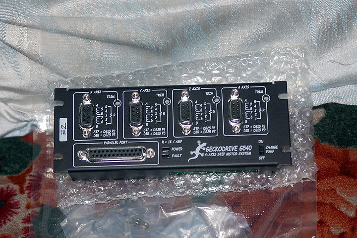
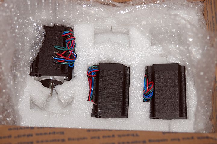
I ordered a G540 and 3 pcs of KL23H284-35-4B last Monday and while waiting for it to arrive I was getting ready with the other things I need for my pcb eating diy CNC.
I read a lot of test setups using the G540 with KL23H284-35-4B steppers that uses 48V power supplies. However, I wonder if I could just make my own power supply with what I have here now.
I have a toroidal transformer that has a secondary of 18V and another one with a 24V output. The 18V one gave me about 24VDC while the 24V about 30VDC. Current is not a problem as these toroidal transformers are more than capable.
My question is, would 24VDC or 30VDC be enough to run the KL23H284-35-4B with the G540 set current at 3.3Amps (will use a 3.3K resistor)?
My diy machine uses ubuntu/emc2 btw.
Thanks in advance!
Jojo
Results 1 to 20 of 23
-
06-15-2012, 10:57 AM #1
 Registered
- Join Date
- May 2011
- Posts
- 0
Gecko G540 with KL23H284-35-4B PSU question...
-
06-15-2012, 04:47 PM #2
Registered
- Join Date
- Apr 2004
- Posts
- 135
Assuming that the supplies provide enough current, then the
difference will be speed. A motor powered by a G540 running
on 48 volts will be capable of approximately twice the speed
of a motor powered by a G540 running on 24 volts.
Regards
Steve Stallings
www.PMDX.com
-
06-16-2012, 07:11 AM #3
Registered
- Join Date
- May 2011
- Posts
- 0
Would there be a significant difference between my 24VDC and 30VDC power supplies?
Or should I use a 48VDC just to maximize the g540?
-
06-16-2012, 08:20 AM #4
Registered
- Join Date
- Apr 2004
- Posts
- 135
The relationship is approximately linear. Ten percent more
voltage will yield ten percent more speed.
Steve Stallings
www.PMDX.com
-
06-16-2012, 09:00 AM #5
Registered
- Join Date
- May 2011
- Posts
- 0
Ok thanks for the replies. I'll try my 30V first then just build a 48V psu if the need arises.
-
06-21-2012, 04:29 AM #6
Member
- Join Date
- Apr 2007
- Posts
- 1955
Sometimes the open voltage of a power supply is quite a bit higher than the under-load voltage. Just an example, I have some 12 V wall warts for a router (the internet kind) and it is 15 volts with no load, but rapidly drops to 12V with even a slight load.
-
06-21-2012, 08:54 AM #7
Registered
- Join Date
- May 2011
- Posts
- 0
Speaking of loads, suppose that I use the g540 in a 3 axis setup with all axis having the same motor and set resistors at 3.48K for a max current of approximately 3.5A per motor.
I read in the g540 papers that the holding torque is about 70% of the set current, so does that mean the g540 will initially draw approximately 7.35A?
-
06-26-2012, 03:54 PM #8
Member
- Join Date
- Apr 2007
- Posts
- 1955
I think I saw the correct value for the PSU in the gecko 540 manual, product description or FAQ, but I don't remember it off hand. The geckodrive web site is pretty good for info.
-
06-28-2012, 05:44 PM #9
Registered
- Join Date
- May 2011
- Posts
- 0
it's true what they say about the Gecko drives... you'll never regret getting them!
:cheers:
-
07-01-2012, 08:43 AM #10
Member
- Join Date
- Apr 2007
- Posts
- 1955
Did you end up getting a pmdx DC setup for that torroid or something else? I am looking around for power supplies as well. Since I bought the G213v, I wondered about getting a 48 v 72 volt supply.
I guess in theory if I found a multi tap torroid, I could get multiple voltages.
What do you guys think ?
-
07-01-2012, 11:44 AM #11
Registered
- Join Date
- May 2011
- Posts
- 0
Hi harynn,
I did end up building my own power supply with one of my 0-18, 0-18 600VA toroid. I tied one of the windings to get 36V and since the primary is rated at 230V and I have a stable 220V AC voltage regulator, I get a nice and stable 48V out of it. It drops to about 46V when all motors are running with the G540 set to 3.3Amps (3.3K set resistor). I used a 35A bridge rectifier and a couple of those computer grade 10,000uf caps.
Here's some pics of the G540 together with the psu that I built.
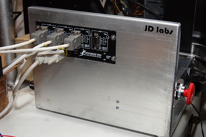
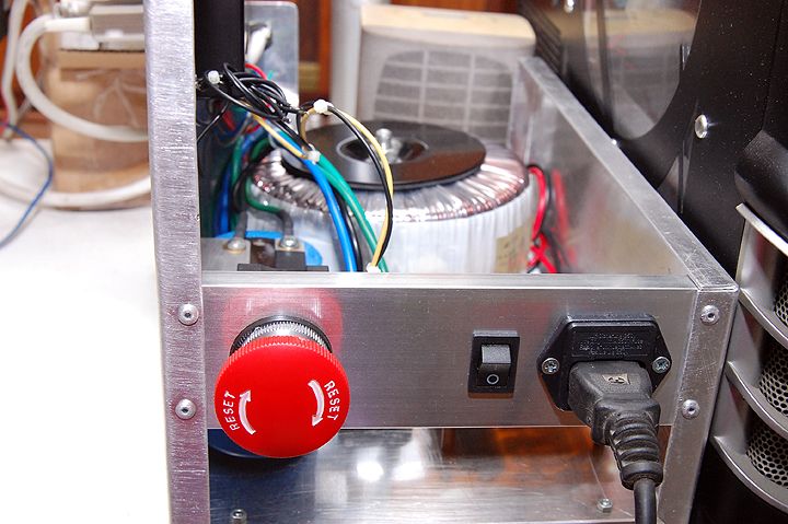
:cheers:
-
07-01-2012, 04:40 PM #12
Member
- Join Date
- Apr 2007
- Posts
- 1955
Nice, you make it look so clean and easy!!!
I will into that approach.
-
07-02-2012, 05:50 AM #13
Registered
- Join Date
- May 2011
- Posts
- 0
 Originally Posted by harryn

Thanks! With the g540, it is really easy and fun. Say goodbye to your frustrations!
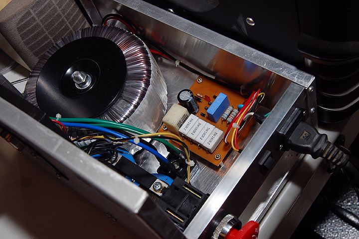
Designing and building the power supply is real easy, it's just a simple linear psu. I did installed a soft start to take care of the inrush current during power on.
-
07-09-2012, 06:47 AM #14
Member
- Join Date
- Apr 2007
- Posts
- 1955
Hi, I see the bleed off resistors and caps in your picture.
The need for a soft start to control in-rush current makes perfect sense. Would you mind sharing how you did this ? Sorry, my background is chemical engineering and I am still figuring out EE, 30 years later.
BTW, I followed the links from PMDX to look at various toroid transformers. It is amazing to me that Hammond built ones are so efficient that they are about 1/2 the mass of the Antek version. Of course, none of them are showing a lot of details, but the Hammond ones are listed transformers.
-
07-09-2012, 10:02 AM #15
Registered
- Join Date
- May 2011
- Posts
- 0
Hi, Originally Posted by harryn
Actually those big white resistors are for the soft start. The 1W 10K bleeder resistor is directly installed on one of the filter caps.
Sure, you can follow this link Boards scroll down until you see the Soft Start Board and Speaker Protector, it's about 3rd from the top. I have written the BOMs and the build guides there and should be helpful to you. Boards are available but you can always make one if you want.
The toroid I used is from Antek, Hammond and Amplino is kinda pricey for my pocket, besides I have tortured most Antek transformers and they do abide by their listed specifications.
-
07-10-2012, 09:48 AM #16
Member
- Join Date
- Apr 2007
- Posts
- 1955
Thanks for that link. I didn't realize that you offered PS boards, esp. for audio work.
I assume that another way around the high inrush current problem is to make multiple smaller PSs and fire them up one at a time. Kind of crude, but maybe effective ?
-
07-10-2012, 01:22 PM #17
Registered
- Join Date
- May 2011
- Posts
- 0
I work for diyAudio and one of my recently posted projects was the Soft Start circuit mainly intended for high powered amp's power supply but can be applied to any psu that needs some inrush control.
Yes that would work, separate psu for every motor but you cannot use the G540 for that but need separate drives for every motor, for example the G203V.
-
07-10-2012, 05:42 PM #18
Member
- Join Date
- Apr 2007
- Posts
- 1955
Thanks. I guess I had hoped that I could parallel 2 or 3 power supplies to make up the (total) required amps.
I am just starting out with building up 1 axis for now using 72 volts x 3.5 amps on a G213v (learning) but eventually it will be 6 motors.
I was hoping that I could just keep adding on PS + drivers + motors modularly in parallel as I go, rather than needing to buy a 20 amp PS now. Is that a bad idea from a PS perspective ?
I know it might not be the most cost efficient in total, but it keeps the entry level costs down while I do some initial setup and tests.
-
07-11-2012, 03:41 AM #19
Registered
- Join Date
- May 2011
- Posts
- 0
No you can't just parallel the power supply but you can always have one for each driver like what you will do with the G213V.
It's not a bad idea from a PSU perspective, it's even a bold/great idea because every driver/motor has it's own PSU.
However, I must agree that this is really not cost effective and an inefficient way of building the PSU.
-
07-13-2012, 12:14 PM #20
Member
- Join Date
- Apr 2007
- Posts
- 1955
Hi, thanks for the reply.
I am trying to understand the technical reason that power supplies cannot run in parallel. I guess in particular, why does it matter if a capacitor bank is fed with one or multiple transformers ?
Is this a phase angle issue or just a concern about getting the identical voltage from each transformer.
On a slightly different aspect, I like that you have the regulation for in-rush current in your design. It is interesting that so few of the PS for cnc seem to include this. I would have thought it would be nearly mandatory during turn - on.

 Reply With Quote
Similar Threads
-
Gecko g540 and spindle relay question
By Claytonc in forum DIY CNC Router Table MachinesReplies: 18Last Post: 08-09-2011, 03:40 PM -
Question on Gecko G540
By blackonblack in forum Gecko DrivesReplies: 9Last Post: 05-30-2010, 03:54 AM -
Gecko G540 input question
By ronncat in forum Gecko DrivesReplies: 7Last Post: 03-10-2010, 07:27 PM -
Question Gecko G540
By rotger in forum CNC Machine Related ElectronicsReplies: 0Last Post: 06-02-2009, 09:59 PM -
Gecko G540 Quick question
By mad_dog096 in forum DIY CNC Router Table MachinesReplies: 0Last Post: 01-03-2009, 04:06 AM
