


I have been thinking on "Closing the Loop" on my desktop router. After a bunch of reading, obviously what I want is glass scales, but that is just too much money for my little machine, so I started thinking about rotary encoders attached to my steppers. This line of thought has led me to designing an encoder, and I have gone so far as to build the encoder wheels, but before I spend any more time finishing them and fitting them to my steppers I thought I would ask a few questions, but I should start with a bit of background.
My desktop router has about 9" x 12" of XY travel, and about 3" of Z clearance. I use it for making PCBs, small parts and molds. The lead screws are 3/8" x 12 pitch, and the steppers are kelings 381oz-in size 23 steppers. While there is a bit of backlash in the lead screws, it is nominal (<0.001"), and KFLOP compensates for it beautifully. This being said, in order to maintain accuracy on PCBs, I have to limit the feed//rapid rates to 30ipm or less. For less critical work I can bump the feeds up to ~90ipm, but I have to keep my "Accel" & "Jerk" numbers relatively low:
(I limit the actual ipm in my settings in KMotionCNC).Code:ch0->Vel=120000; ch0->Accel=60000; ch0->Jerk=200000;
On a 4x6 PCB of fairly low density with trace widths > 0.020" and spacing = 0.020" I get very good results @ 30ipm or less. Above 30ipm things go awry, sometimes in the X, sometimes in the Y, sometimes in both. As the feed rate increases, so do the errors. Obviously there are "missed steps". The cumulative affect is as much as 0.050" which is simply unacceptable.
Ignoring backlash and microsteps, my setup should yield 1 / (200 * 12) Inches per Step = 0.0004166In/Step. My thought is that by closing the loop with 200ppr encoders tied directly to the stepper shafts I should be able to limit position errors by +/- 1 step = ~0.001". With the same setup 400ppr encoders should limit the error to +/- 1/2 a step etc, etc. In theory this should allow me to run the steppers near the top of their speed curve on PCBs (obviously there are negligible cutting forces involved) and KFLOP will correct for the missed steps.
I do not mean to be obtuse, but I want to make sure I am thinking this through correctly. By adding 200ppr encoders directly to the steppers I should limit absolute errors to 1/(ppr * lead screw pitch)? OK, assuming this is true, am I actually losing absolute accuracy? By this I mean, if KFLOP calculated an axis needs to move 0.020", given my setup params (16uSteps/Step, 200 Steps Per Rev, 12 Rev Per Inch = 38400uSteps/Inch) it should travel 768uSteps (48 encoder pulses using a 200ppr encoder) the encoder could reach the position anywhere between 752uSteps and 784uSteps (assuming no missed steps). Does KFLOP search for the center, leading edge, trailing edge or am I just over thinking this? LOL. If I made the "quantum leap" to 12800ppr encoders would KFLOP oscillate the driver between two uSteps? Obviously there is a 1:1 correlation between absolute accuracy and ppr in the encoder; by using a low resolution encoder (200ppr) am I robbing Peter to pay Paul, but gaining speed in the process or am I just robbing Peter?
The encoder wheels I made have 100 slots. Using two sensors this implies 200ppr in quadrature. Electronically it is trivial to use 4 sensors to achieve 400ppr in quadrature; however mechanically this is slightly more complex and perhaps more prone to vibration and shock causing misalignment. 8 or more sensors are probably beyond what I could achieve with my tools. Obviously I could build encoder wheels with more slots, but this would require larger diameter wheels (1/32" slots/spaces is the best I have been able to do while keeping tool breakage to a minimum, this implies a roughly 2" diameter encoder wheel (200 * 1/32" = 6.25 ==> 6.25"/Pi = 1.9894" median diameter) which mates nicely with the NEMA23 frame. To achieve 200 * 1/32 slots/spaces implies a 4" encoder wheel, certainly achievable if 800ppr is truly requisite, but I am hoping 200 to 400 ppr will be enough....?
Thanks in Advance for reading through this, hopefully I can get some guidance and close the loop....
Hunter
Thread: Thoughts on "Closing the Loop"
Results 1 to 14 of 14
-
10-05-2012, 02:12 PM #1
 Registered
- Join Date
- Mar 2007
- Posts
- 217
Thoughts on "Closing the Loop"
-
10-05-2012, 03:29 PM #2
Community Moderator
- Join Date
- Dec 2003
- Posts
- 24220
All optical encoders typically only use two sensors to detect the two pulses which are spaced 90° apart (90° = in quadrature), the subsequent electronics just detect the 2 leading, 2 trailing edges to obtain the x4 figure. Originally Posted by Fish4Fun

On home made encoders the 100 slot optical encoder is usually at the limit for simple reading, after this the lines spacing is too dense for this method and a method called the Moiré effect is used.
Al.CNC, Mechatronics Integration and Custom Machine Design
“Logic will get you from A to B. Imagination will take you everywhere.”
Albert E.
-
10-05-2012, 04:26 PM #3
Registered
- Join Date
- Mar 2007
- Posts
- 217
Thanks for the response Al! Some quick reading on the Moiré effect proved interesting. While I am fairly certain I can mux 4 sensors to provide a true 2X quadrature output (not edge sensing), that is secondary to 200ppr or 400ppr being enough to close the loop effectively. Assuming 200ppr (two sensors, 100 slots) will this, in theory, keep me within +/- one step in a closed loop? If not, what is a reasonable number of pulses per revolution to keep me +/- 0.001"? My thinking is outlined above, my inquiry here is to ensure I have used the proper logic. Calculations performed on faulty logic generally produce worthless results; I just want to make sure my thinking is right.
Thanks!
Hunter
-
10-05-2012, 04:56 PM #4
Community Moderator
- Join Date
- Mar 2003
- Posts
- 35538
People run 4x8 routers with those motors at 1000ipm without losing steps.
The simplest thing to do is find out why you're losing steps and fix it. You have far more power than you need on a machine that size to be losing steps.Gerry
UCCNC 2017 Screenset
http://www.thecncwoodworker.com/2017.html
Mach3 2010 Screenset
http://www.thecncwoodworker.com/2010.html
JointCAM - CNC Dovetails & Box Joints
http://www.g-forcecnc.com/jointcam.html
(Note: The opinions expressed in this post are my own and are not necessarily those of CNCzone and its management)
-
10-05-2012, 08:45 PM #5
Junior Member
- Join Date
- May 2006
- Posts
- 4045
Hi Hunter,
I commend you on attempting to build your own encoder. But I would think that would be very difficult to get everything mounted accurate enough. You seemed to miss Al’s point that 2 sensors on a disk with 100 lines will provide 400 quadrature counts without doing any multiplexing. I’m curious what you plan to use for sensors. I’m not sure if you are aware but most encoders don’t use a small sensor to detect one line, but rather a sensor that is the size of multiple lines and then there is a mask with a few lines close to the disk so as the disk rotates there is like a shutter effect. This helps average out imperfections in individual lines as well. Here is a description.
With regard to your question on how closed loop step/dir works: The stepper motion will move in a manner very similar to open loop operation with a difference that there is a small offset applied to the final commanded trajectory. This offset will be continuously adjusted based on what the encoder is actually reading compared to what it is expected to be reading. How and at what rate the offset is adjusted is determined by your servo PID and filter parameters. The simplest case is where the I gain only is used and the adjustment is very gradual. In this case for example a motion might complete and the encoder might indicate it is off by two encoder counts. This will cause the offset to ramp at a rate determined by the encoder error of 2 x I gain. This will eventually generate uSteps which will eventually cause motion to reduce the encoder error. See also. Note that even though a uStep is commanded it is unlikely that the motor moves until enough uSteps are made to generate enough torque to overcome friction. If the encoder error becomes zero, no further adjustment will be made. KFLOP is careful to perform all calculations with high precision floating point math. The desired final position might then be fractional encoder counts (ie. 100.3 counts). In this case it will never be possible to have zero error. Encoder=100 will be too low and 101 too high. The result will be that the encoder position will dither between 100 and 101 where 30% of the time will be spent at 101 and 70% at 100 such that the average position will be 100.3. Sometime this dither can be desirable and sometimes annoying. While in motion this can actually improve resolution beyond the basic encoder resolution. The KFLOP Deadband Parameters can be used to stop attempting to make corrections when within a certain tolerance (ie 0.5 encoder count).
In summary I think a 400 count/rev encoder could make sense to improve accuracy and reliability. The higher resolution of uSteps is useful in helping to servo to within one or several encoder counts that would be more difficult with larger usteps or full stepping.
One thing that would be worse is that the backlash compensation will probably no longer work well as the motor will be making positive and negative motions to make encoder corrections.
The other great thing about having an encoder it to be able to detect when a miss-step occurs and to be able to see how and what happened. Otherwise you are operating blind.
With regard to miss-steps: A stepper will always jump an integer number of motor poles. A motor pole is 4 full steps or with 16x microstepping 64 uSteps. So you might mark your motor shaft and after you seemed to have drifted off, return back to a known position and see if the motor shaft is off. If so move in 64 uStep increments to see if that seems to be the amount off. If not, then something else is going on.
I noticed your max Velocity of 120,000 uSteps/sec is probably too high. This would be:
120000 / (200x16) x 60 = 2250 RPM
A common problem I see is that Users inadvertantly limit velocity by reducing acceleration (or jerk) and think everything is fine. But then on a longer move the velocity goes too high and they have a problem.
RegardsTK
http://dynomotion.com
-
10-05-2012, 09:08 PM #6
Community Moderator
- Join Date
- Dec 2003
- Posts
- 24220
Yes, although the link does not go far enough to explain the Moiré effect, a small piece of the scale is carried by the reading head, but slightly skewed. Originally Posted by TomKerekes
in relation to the main grating. The resultant effect is, that due to the Moiré effect, the photo receiver now *sees* an alternating light-dark band, the width of each band is around half the verticle height of the grating, the alternating bands move like a shutter, perpendicular to the direction of motion, i.e. on a linear scale, if the head is moving in a horizontal direction the 'shutter' appear to be rotating up or down,depending on the direction of movement.
This is obviously much wider than the space between the grating, the band will change from light to dark for one increment of the scale.
The output of the head is two sine waves 90° apart, hence quadrature.
Al.CNC, Mechatronics Integration and Custom Machine Design
“Logic will get you from A to B. Imagination will take you everywhere.”
Albert E.
-
10-06-2012, 12:16 PM #7
Registered
- Join Date
- Mar 2007
- Posts
- 217
Al, Gerry, Tom,
Thank you all for providing great information! I will need to think more on the pros and cons of closing the loop before I go any further with my encoder project. My immediate thought is that loosing backlash compensation is a pretty high cost for closing the loop simply to increase cutting speed. At the end of the day most of my PCBs are one-off prototypes that I spend (at the least) several hours optimizing for my router, so ultimately how important is the length of cut time?
As Gerry (and Tom) pointed out, I may have other problems that need addressing. Obviously I need to reduce the Vel setting, what would be a reasonable Max RPM?
@ 1200rpm & 16uSteps ==> Vel = 64000
@ 900rpm & 16uSteps ==> Vel = 48000
@ 600rpm & 16uSteps ==> Vel = 32000
1200rpm / 12rpi = 100ipm
900rpm / 12rpi = 75ipm
600rpm/12rpi = 50ipm
I had a great deal of trouble with Mach3 and the Parallel port wrt any speed over ~25ipm, with the KFLOP I have run "air cuts" @ 120ipm, but even the lightest "real" cuts would result in motor locking, so I set the maximum feed rate in KMotionCNC to 90ipm (but I left the KFLOP setting @ Vel = 120000, thinking KMotionCNC would override the KFLOP setting). @90ipm I can "level a spoil board" or other non-critical tasks, but for anything critical I keep the KMotionCNC settings limited to 30ipm or less. Will reducing the KFLOP Vel setting improve performance in general? What are reasonable Accel & Jerk figures? There are settings in both my init file and KMotionCNC for Vel & Accel, is it important that they match? Which one "wins". If the Gcode sets the feed rate (G1Z-0.2500F30.0) again, which one wins? In a jog (G0X-0.5562Y0.3500Z0.2000) what speed is used by default?
I have a fairly large (for me) PCB I need to run. I will try reducing the KFLOP setting to 32000, and I will push the KMotionCNC settings up to 50ipm and see what happens. Worse case I mess up a 4in x 6in piece of PCB material, lol.
Al,
The PDF contained a great deal of information on sensors of all types, and I found the reading interesting. What were the first 22 Chapters about and are they readily available? (It appears to be a text book, just curious if the rest of it would make good reading).
Tom,
There is a typo in your documentation:
Not criticism, just an observation.a rotary encoder with 2000 lines/rev will profuce 8000 quadrature counts/rev, 10000/8000 = 1.25).
Thanks again to all for the help & info
Hunter
-
10-06-2012, 10:28 PM #8
Community Moderator
- Join Date
- Dec 2003
- Posts
- 24220
Unfortunately, this is all I have of the publication. Originally Posted by Fish4Fun
I originally acquired most of the details on encoders from Ferranti-Packard instruction, I think they did some pioneering on optical quadrature encoders.
Al.CNC, Mechatronics Integration and Custom Machine Design
“Logic will get you from A to B. Imagination will take you everywhere.”
Albert E.
-
10-07-2012, 04:50 AM #9
Junior Member
- Join Date
- May 2006
- Posts
- 4045
Hi Hunter,
I think most Steppers are limited to about 1000RPM.
KMotionCNC treats Rapids (G0) and Jogging differently than Coordinated Motion (G1,G2,G3).
Rapids move each axis independently with 3rd order "S" curve motion that use the Max Velocity, Accleration, and Jerk settings in KFLOP in units of Steps.
Trajectory Planned Coordinated Motion does 2nd order motion using the Max Velocity and Acceleration in KMotionCNC in units of inches (Jerk is infinite). GCode Feed Rates will automatically be limited so no axis exceeds the Max Velocity Setting for the axis.
To simulate and test 2nd order motion in the KMotion Step Response Screen set the Jerk value to infinity (1000X the Acceleration number). 3rd order (Jerk limited) motion is slower than 2nd order motion given the same max Velocity and Acceleration, but usually a higher acceleration can be used that results in overall faster and smoother motion.
RegardsTK
http://dynomotion.com
-
01-01-2014, 03:27 PM #10
Registered
- Join Date
- Mar 2007
- Posts
- 217
So, it is 15 months later, and (for better or worse) I have ordered three of these: Encoder 600P R Incremental Rotary Encoder AB Phase Encoder 6mm Shaft w Coupling | eBay to give "closing the loop" a try. Hopefully they should be here before the 1st of February, and hopefully by then I will have had time to do some other "maintenance oriented improvements" to my little cnc stage. It is really time to properly install limit switches and "home" switches, spindle control, "lights" and perhaps even a vacuum system not to mention make some new lead-screw-nuts....etc etc.
During the past months my little machine has been rock solid, and choosing to "close the loop" is really more of an intellectual pursuit than anything based on "need". I just figured while I had it torn down would be a great time to give closed-loop cnc a try. If it doesn't work out, the encoders were cheap enough and I can chalk the expense up to experience (hehe: "Don't buy cheap encoders", LOL!). I have been running a fair number of SMD prototype circuit boards and getting good to excellent results with traces/spaces down to ~10mil/20mil, but I would love to see 10mil/10mil or even 10mil/5mil. I am also thinking about adding a "3D Print head", or perhaps just building a completely new 3D print machine. The "fine" print heads use a .3mm nozzle (0.0118in), indicating stage accuracy should be better than +/- 0.005in to take advantage of them, and I am not quite there, so any improvements introduced by closing the loop will be helpful if I use this machine for 3D printing....time will tell, lol.
Tom,
I hope that your support efforts @ cnczone have helped get the KFLOP some well deserved exposure! It is a FABULOUS device and I wouldn't trade mine for the world. From the growing number of posts, it would APPEAR the KFLOP is gaining some popularity; I hope that is true and that your sales will continue to expand in 2014. I am going to begin a new build in Late January or Early February, and I look forward to ordering a new KFLOP to dedicate to that build. (HEHE, I am finally going to get a chance to use the "KSTEP" I ordered back before they were released ! ;-) I am still more than willing to write a "How To Get Started" for the KFLOP, but as you pointed out way back then, the KFLOP is just too versatile to "dumb it down" enough for such a guide to be meaningful to more than a very small handful of people. Perhaps when I get the encoders installed and working I will give a go @ how to set the KFLOP up for a 3-Axis Stepper machine in both Open and Closed loop operation. I know that won't address more than a small percentage of the people buying KFLOPs, but perhaps it ill make the KFLOP more accessible to the average DIYer.
I will post back when I have the encoders installed and am banging my head against the wall :-)
Happy New Year!
Fish
-
01-01-2014, 08:26 PM #11
Junior Member
- Join Date
- May 2006
- Posts
- 4045
Hello Fish!
I've never seen optical encoders that inexpensive. Although only single ended, open collector, and somewhat slow.
Let's see: 20HKz/600 = 33 Revs/sec = 2000RPM - that should be fine.
It would be interesting to capture and plot worst case following errors to see how close your system gets to losing steps/stalling and what the resonances are. Then see if it possible to reduce and dampen the errors with feedback.
Good Luck!TK
http://dynomotion.com
-
01-02-2014, 08:58 PM #12
Registered
- Join Date
- Mar 2007
- Posts
- 217
Hey Tom!
Yea, I thought they were cheap enough, and I obviously will not have any trouble complying with the 2000rpm, LMAO. I figure I will have as much time/effort in making suitable couplers as the encoders are worth, but for less than $50 delivered I thought, "Why Not?". I have everything on my little desktop router tweaked from an electronics point-of-view, so as long as I obey my speed rules I am no longer having any "missed step" problems, but all the "crashes" over the last couple of years have left my lead nuts more than a bit sloppy, so fixing them them is a high priority when I start the maintenance.
Do you think I might need to buffer the encoder outputs.....I know, no way to know anything until they get here. Before I bother starting the install I will hook them up to a drill and my DSO and see what the signals look like, then I will know if anything needs to be done..
Thanks!
Fish
-
01-02-2014, 10:20 PM #13
Junior Member
- Join Date
- May 2006
- Posts
- 4045
Hi Fish,
It seems the outputs are NPN type which should mean that the outputs sink low and then float when off. I didn't see any specs. I would try ~ 500ohm pull up resistor to +5V near KFLOP and then scope the signals at KFLOP to see what they look like regarding ringing and so forth.
RegardsTK
http://dynomotion.com
-
01-15-2014, 06:43 PM #14
Registered
- Join Date
- Mar 2007
- Posts
- 217
Sooooo, the encoders came in....I think they are going to work :-) Following are a couple of scope shots from One encoder just stuck in a drill to get a look @ the signal. The first is ~214Hz (~21.4rpm) and the second is ~13.4kHz (~1340rpm).
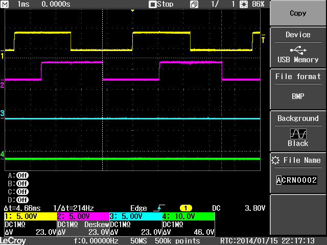
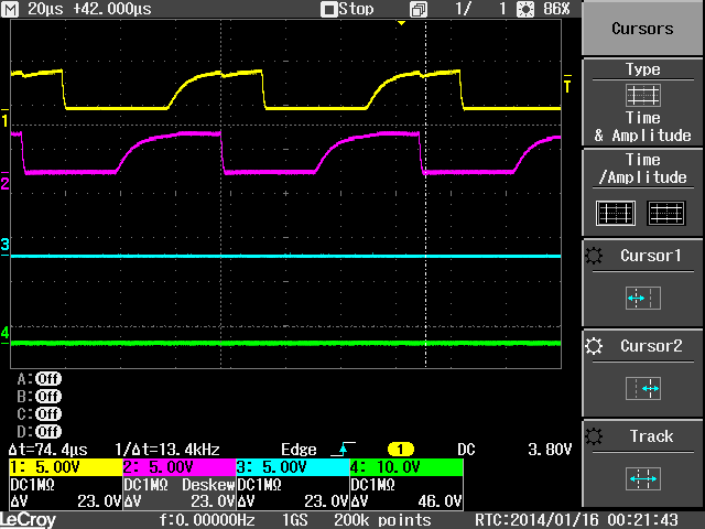
The encoder specs are 7-24V input, so I just used a 12V wall-wort and a couple 10k pull-ups. I am sure I can "clean" the signals up by tweaking the pull-up values. If not, perhaps adding a schmitt trigger buffer, or perhaps a flip/flop, will "square things up". In any case, I think the signals are "clean enough" to move directly to building some mounts and doing any "final tweaking" once they are installed!
I am excited at the prospect of getting my little desktop router fitted with these :-) I will post more screen shots once everything is installed (likely several days as I have some other maintenance to perform while it is "out of the case" ;-) ).
Fish
Edit==> I won't bother to post a DSO shot, but with 1k Pull-Ups in place of the 10k Pull-Ups the 13.4kHz signal looks almost identical to the 214Hz signal :-) MUCH better than I was thinking, and I don't expect my steppers to be achieving anywhere close to 1340rpm. So, onto the mounts :-)

 Reply With Quote


Similar Threads
-
Your thoughts about the new "Gearotic Motion" software
By ynneb in forum CNC (Mill / Lathe) Control Software (NC)Replies: 35Last Post: 11-21-2019, 04:10 PM -
Haas "TL2 & TM2" thoughts
By pugsley in forum Haas MillsReplies: 12Last Post: 01-13-2011, 02:33 PM -
inside arcs with comp doing "loop de loops"
By Mikey69 in forum FanucReplies: 11Last Post: 06-01-2009, 03:13 PM -
"Bolt-on" CNC retrofit thoughts
By kong in forum Uncategorised MetalWorking MachinesReplies: 4Last Post: 02-20-2005, 07:11 PM
