


I want to build a CNC capable of cutting wood and aluminum (at a very slow feed rate), and the design that I am drawn toward is what I think is considered a CNC router table.
I am considering using supported linear rails for the X, Y, and Z axes. Something like the ones listed here on Ebay:
3 SBR20 400 900 900mm Sets 3 ballscrews RM2005 900 900 400mm BK BF15 | eBay
I'm thinking my machine will basically look like the one shown in this video:
[ame=http://www.youtube.com/watch?v=dwbMh7zXlt8]CNC jogging - YouTube[/ame]
Are there similar builds documented here on CNCZone or elsewhere that I could look at as examples?
Are these types of components---supported linear rails and ball screws--a good choice? Should I be looking at something else for the basis of my machine?
Don't want to ask too much or add too much detail in this first post since there may be a thread or web site out there that I'm not aware of.
Thanks,
Daniel
Results 1 to 20 of 22
-
12-23-2012, 01:01 AM #1
 Registered
- Join Date
- Dec 2012
- Posts
- 0
Starting at New CNC Build -- Guidance Needed!!
-
12-23-2012, 02:26 AM #2
Registered
- Join Date
- Jul 2009
- Posts
- 690
That one is a machine I built a couple of years ago, which I still use from time to time to make parts for other machines (this includes cutting 1/2" aluminum). It doesn't have a build log as it was mostly improvised from scrap and was build using only a crappy bench drill and a hand saw, so I think it's far from being a good example even if it works OK (there's been a couple small improvements since that video, tough, like protecting the rails from dust and finishing the loose wiring). It uses SBR16 rails and RM1610 ballscrews, and 3/8" all-thread rod on the Z (with dual DumpsterCNC anti-backlash nuts).
The components are pretty good for the money, considering that using profile rails can cost 3x more, but there is usually the need for some work to be done on them to make them work right (especially the BK/BF blocks).
I use RM1610 ballscrews as they spin half as fast as RM1605 (or RM2005, in your case) for a given linear speed. The faster a screw spins, the more it whips, this can damage the screw in the long term, increases vibration and can lead to machine stall. The bigger diameter, the longer the screw can be, but this means stringer motors/drivers to drive them, and also more inertia, so acceleration might suffer.
What is your total budget? Do you have the drivers/motors already? You want the machine as a hobby, or for production runs?
If you haven't bought anything yet... don't impulse buy!! This is one of the most common mistakes made by people building their first machine, and it's not uncommon for many to end up with a pile of unused parts. Read a lot, ask even more, make drawings, check comments people has made about each part you're interested in buying, and you'll most likely save yourself quite some money and trouble.
If you have any questions don't hesitate to ask.http://www.build.cl
-
12-23-2012, 06:34 AM #3
Registered
- Join Date
- Dec 2012
- Posts
- 0
Wow, thanks for that quick reply, and I can't believe that the example I came across on youtube is a machine that was built by someone here!
To try and answer some of your questions:
-- My total budget is $1300.
-- I do have stepper motors already but no drivers. I had motors left over from past projects. They are 680 oz-in holding torque, 2.80A, 90V
-- This machine will be for hobby/prototyping different ideas for new designs.
I completely agree with your advice, and thanks for those comments. I'm modeling up the design I plan to build in SketchUp, and I've been looking at components online for about a month. I hope to post the information on the build online, probably in a blog just because that's an easier format for me to organize the information.
Some questions I have:
Are there other components that I should consider for performance vs. the cost? From your initial comments it sounds like these may be OK, but I'm definitely not locked in. Also, you said the BK/BF blocks especially required some work--could you give me more information on what type of work I might be looking at?
Do you think that it's worth the extra $$'s to go for the larger diameter rails and ball screws? I'm sure that especially with the ball screws this is dependent on the motors and the speeds I hope to achieve, since increasing the diameter quickly increases the weight.
I'm also curious about the software and electronics that I should consider, so any tips there are also appreciated. So much to learn . . .
Thanks again,
Daniel
-
12-23-2012, 09:06 AM #4
Registered
- Join Date
- Jul 2008
- Posts
- 390
This is very good advice. I am guilty of this and regret some of my purchases. Thankfully I haven't made too many bad decisions... Please follow this piece of advice! Model your parts and plan out the build before the shopping begins. Originally Posted by Walky

What is the impedience (mH)? This will be a useful piece of information when it comes to picking a PSU in the future. Just a heads up.I do have stepper motors already but no drivers. I had motors left over from past projects. They are 680 oz-in holding torque, 2.80A, 90V
Things that I have learned with electronics & CNC:I'm also curious about the software and electronics that I should consider, so any tips there are also appreciated. So much to learn . . .
eBay = NO!
Any driver that starts with TB65 = NO!
Gecko is a popular brand around here. I'd recommend it. See those two NO!'s above? Guess what I did before I learned and went with Gecko's? Yep you guessed it. Don't fall for it.
What type of material are you intending on cutting?This machine will be for hobby/prototyping different ideas for new designs.
Keep in mind though that a thicker ballscrew will be less prone to whiplash (I think there is a more technical term), allowing for increased speeds.Do you think that it's worth the extra $$'s to go for the larger diameter rails and ball screws? I'm sure that especially with the ball screws this is dependent on the motors and the speeds I hope to achieve, since increasing the diameter quickly increases the weight.
A lot of your decisions will be based off of the end goal you are trying to achieve (precision, speed, rigidity, cost) with this machine. You can't get a machine that is 5'x5'x1' with .001 precision that cuts steel for $2000. You know this of course, but it its necessary to outline your goals (I.E. what needs to be cut and how accurately) at the start otherwise it is easy to get carried away (speaking from experience).
I hope this helps a little bit. Welcome to the world of CNC.
-
12-23-2012, 02:40 PM #5
Registered
- Join Date
- Dec 2012
- Posts
- 0
The phase resistance of the steppers I have is 1.7 ohms, and the phase inductance is 7.7 mH. Thanks for the heads up.
I do have some background in motion control and even converted a bench top milling machine to CNC about 7 years ago, and I have known about Gecko's for probably close to 12 years. Definitely a front runner for my drivers.
The hardest material I hope to cut is aluminum. I would like a build area of at least 12" x 12" x 5" and an accuracy of maybe 0.005". With the linear rails and ball screws I've been seeing on Ebay, it seems like I might as well go for a bigger build area for only a marginal increase in price. Unless this greatly reduces accuracy, I will probably build a machine with a build area much bigger than 12" x 12".
I don't have anything specific in mind to build that tells me 0.030" would be too much slop, or 0.001" is required, but if I can build a machine that would consistently perform down in this range, I think it would be incredibly useful. I know throwing out tolerance numbers like that is only a small fraction of the information that goes into determining how accurate a machine needs to be, but I guess I'm trying to say that I want it to be pretty accurate.
Is it reasonable to try and make a machine of the 3D router type from the individual components up that will be as accurate as a bridgeport or similar knee mill? I know I will not be able to cut much material at a time, but if I'm willing to go slow can these types of machines deliver that type of accuracy? Or am I on the wrong track?
Also, for $1300 total, is there an off the shelf machine I should consider? I mentioned I have converted a machine to CNC before, and I have a working 3D printer I built, so I have the technical know-how and enjoy building things, but if there is a turn key machine out there that would give me better performance for the buck, I'm open to that.
Thanks,
Daniel
-
12-23-2012, 03:32 PM #6
Community Moderator
- Join Date
- Mar 2003
- Posts
- 35538
It might be a little small, but these get excellent reviews. Originally Posted by dtmille2
microcarve MV3Gerry
UCCNC 2017 Screenset
http://www.thecncwoodworker.com/2017.html
Mach3 2010 Screenset
http://www.thecncwoodworker.com/2010.html
JointCAM - CNC Dovetails & Box Joints
http://www.g-forcecnc.com/jointcam.html
(Note: The opinions expressed in this post are my own and are not necessarily those of CNCzone and its management)
-
12-23-2012, 05:08 PM #7
Registered
- Join Date
- Oct 2004
- Posts
- 590
Both the supply voltage and the inductance are high for Gecko drives.-- I do have stepper motors already but no drivers. I had motors left over from past projects. They are 680 oz-in holding torque, 2.80A, 90V
The phase resistance of the steppers I have is 1.7 ohms, and the phase inductance is 7.7 mH.
-
12-23-2012, 07:00 PM #8
Registered
- Join Date
- Jul 2009
- Posts
- 690
Here is some information regarding the BK/BF blocks issue:
http://www.cnczone.com/forums/diy-cn...2_mount-2.html
Those sure look like overkill motors for a medium/small machine, speed/acceleration will suffer and the cost of buying the right drivers and power supply for them might get close to the cost of buying more adequate drivers and motors. For a 12" x 12" you'll most likely be fine with 280 oz-in unless you're building a really heavy machine. 1605/1610 ballscrews should be fine for those travels. 1610 should get you better rapids, but they are a little more expensive than 1605. 1605 will have twice the resolution but depending on the machine design it might not be even noticeable in practice; if you decide to go with a larger machine then 1610 might be a better choice to reduce whipping.http://www.build.cl
-
12-23-2012, 11:30 PM #9
Registered
- Join Date
- Dec 2012
- Posts
- 0
ger21 -- Thanks for the note about the microcarve MV3. Something to think on at least.
Walky, thanks for the info on the BK/BF blocks. I will keep that in mind if I end up using those components.
I'm going to hunt around the basement a little more and see what other motors I might have on hand. As far as the Gecko drives to use, should I look at the G540, or should I go with three separate drivers for the three axes?
It would eat up a big chunk of the budget, but I could go with the G201X drivers, which are up to 80V to handle the NEMA 34's I have mentioned so far. How much would it cost to get a power supply that could pump out power to three of these motors running at 80V? I'm not sure where to look for power supplies in this spec range.
OCNC--the Gecko drives on their web site list inductances in the 1 - 50 mH range. 7.7 mH falls in that range, certainly, so are you saying that from your experience 7.7 mH is a high value for Gecko drives, or am I missing something? And if that is too high for Gecko drives, are there alternatives?
As is so often the case, maybe the "free" motors I had lying around could lead me into more headache and cost later on that buying new motors suited for the purpose. All I can do is keep learning and see where I end up . . .
Thanks,
Daniel
-
12-23-2012, 11:53 PM #10
Registered
- Join Date
- Oct 2004
- Posts
- 590
The higher the inductance the more difficult it is for the motor to reach a particular speed quickly. Hence you'll see lower top speeds and accelerations with higher inductance motors. Most of the motors that one sees being used in the DIY world seem to be between 2-4mH. This may be largely due to the fact that the rule of thumb for determining the optimum stepper voltage is to multiply 32 times the square root of the inductance in milliHenries. For a 3mH motor this gives an optimum voltage of 55V. For an inductance of 7.7mH the optimum voltage is ~89V. This is 9V more than the voltage rating of the single Gecko drives. A 50V power supply is readily available and also the voltage limit for the multi drive G540 from Gecko. Combine these elements and you can see why the lower inductance motors are favored. Of the motors that Gecko is currently selling I see that one is rated at 12.4 mH. An application using a motor with a 50mH rating would I believe be highly unusual.OCNC--the Gecko drives on their web site list inductances in the 1 - 50 mH range. 7.7 mH falls in that range, certainly, so are you saying that from your experience 7.7 mH is a high value for Gecko drives, or am I missing something? And if that is too high for Gecko drives, are there alternatives?
-
12-24-2012, 12:05 AM #11
Registered
- Join Date
- Dec 2012
- Posts
- 0
Walky,
I have a question about your machine that I linked to in my first post:
CNC jogging - YouTube
Do you have problems with chips etc. getting into the bearings that slide along the linear rails on the lower sides of the table?
I like having the bearings there to make the connection to the gantry more straightforward, but I wonder if I will run into trouble since I think the bearings I'm looking at on Ebay are not sealed very well and may be subject to gumming up or damage once the chips start flying.
I'm also curious if anyone has suggestions or examples of other ways to orient the rails and bearings, whatever the reason may be.
Thanks,
Daniel
-
12-24-2012, 12:07 AM #12
Registered
- Join Date
- Dec 2012
- Posts
- 0
Thanks for the great explanation OCNC, makes perfect sense. Still digging through the basement . . . Originally Posted by OCNC
-
12-24-2012, 01:19 AM #13
Registered
- Join Date
- Jul 2009
- Posts
- 690
Yes, there were some problems but not with chips (the seal takes care of them) but with dust, as the router pushed air towards the piece and blown all chips and dust towards the sides. It actually worked like that for a couple of years of very occasional use, but the problem became obvious just very recently once I started cutting aluminum using WD40 as lubricant, since the mix is pretty nasty. I removed all blocks and cleaned up the bearings carefully, then they went back to work like new. Then I added long brushes on each side of the table over the rails (the kind usually goes under doors, which has adhesive in the plastic part). Now they stay pretty clean and just need some brushing from time to time to remove sticking dust (from the air, not from the table). There are lots of other ways to prevent dust from getting into the bearings so I wouldn't rule out that rail setup just because of that. Anyway, you can search for SBR rails on CNCZone and you'll find dozens of builds using different rail setups.
http://www.build.cl
-
12-26-2012, 01:46 AM #14
Gold Member
- Join Date
- May 2005
- Posts
- 3920
The comments about impulse buying should be read again and again because I'm another guy guilty of such. In my case it hasn't been CNC parts but other shop related things. Controlling impulse buying will go a very long way to making the project feasible.
Well that is actually a good thing as you have your own experiences to build upon. Originally Posted by dtmille2
A couple of things. First; in a machine that small consider a fix gantry / moving table design. The extra space used shouldn't be a problem and the design ends up being simpler and more rigid. I'm not a fan of moving gantry systems at all but do acknowledge that they save space. In this case I see a moving table design as a no brainer.The hardest material I hope to cut is aluminum. I would like a build area of at least 12" x 12" x 5" and an accuracy of maybe 0.005".
Second; you should be able to get very good accuracy but you need to specify over what distance. This isn't a maybe you should shoot for precision as tight as funds permit.
Now you are being wishy washy with your specs. The thing here is that if you go real large, building a stiff accurate machine becomes much more demanding. Not just in material costs but in time and effort. Now granted if you can find bargains at the junk yard or from donor hardware you can manage some of that cost. However if you have to go out and buy steel or aluminum plate or sections your costs can inflate quickly. This isn't insignificant if you want to maintain a build suitable for aluminum machining and maintain rational accuracy.With the linear rails and ball screws I've been seeing on Ebay, it seems like I might as well go for a bigger build area for only a marginal increase in price. Unless this greatly reduces accuracy, I will probably build a machine with a build area much bigger than 12" x 12".
Obviously it depends upon what you are making but 0.030" won't even cut it for many wood working tasks.I don't have anything specific in mind to build that tells me 0.030" would be too much slop, or 0.001" is required, but if I can build a machine that would consistently perform down in this range, I think it would be incredibly useful.
Which is where your budget comes into play. If you want an extremely accurate machine, on a fixed budget, I'd concentrate on making it compact and stiff.I know throwing out tolerance numbers like that is only a small fraction of the information that goes into determining how accurate a machine needs to be, but I guess I'm trying to say that I want it to be pretty accurate.
Sure why not? It might be difficult on your budget, especially if you want a very large capacity. You may also need access to machine tools and the like.Is it reasonable to try and make a machine of the 3D router type from the individual components up that will be as accurate as a bridgeport or similar knee mill?
Wrong track? That is far more difficult to answer. If your primary goal was to machine metals I'd have to say yes you are on the wrong track and that a mill conversion makes more sense. However if your goals are machine a wider array of materials (plastics, wood, Aluminum, circuit boards & etc) then I suspect you are likely on the right track.I know I will not be able to cut much material at a time, but if I'm willing to go slow can these types of machines deliver that type of accuracy? Or am I on the wrong track?
As for accuracy, yeah a router type machine can be very accurate, however we need perspective here. You can buy $5000 router machines or $50,000 machines. Likewise you can build your own to equal the quality of either. The question isn't can router type machines do it, but rather are you equipped to make one to a higher quality level.
Nope.Also, for $1300 total, is there an off the shelf machine I should consider?
Obviously I haven't seen everything out there but to the best of my knowledge nothing out there comes close in that price range. That is a machine that can give respectable performance in Aluminum while maintaining any sort of precision. Even the home built machines that are capable and where built on the cheap succeed due to the builder ability to find the elements of those machines at an exceptional discount. That is junk yard prices, donor machines, freebies, auctions and other approaches to distancing ones self from retail prices. If you are willing to give up a bit on precision, repeatability and general quality then the discussion becomes more interesting.I mentioned I have converted a machine to CNC before, and I have a working 3D printer I built, so I have the technical know-how and enjoy building things, but if there is a turn key machine out there that would give me better performance for the buck, I'm open to that.
It is all about what you want. It is very possible to make a very accurate router type machine, it isn't however a cheap endeavor. Further you will need access to the required machining capacity.Thanks,
Daniel
-
12-26-2012, 05:02 AM #15
Gold Member
- Join Date
- Apr 2009
- Posts
- 5516
Your steppers are beasts! You probably won't get their full benefit with the GeckoDrive stuff, since their max operating voltage is 80V. You can run them at a lower voltage but they'll likely lose torque faster. You have to consider that stepper drives with the ability to handle voltages higher than 80V are not exactly cheap as well as the power supply itself. Leadshine makes relatively affordable drivers, and their digital drives are supposedly excellent and quiet-operating (I have a set but have not completed my control box build - yet.) Search eBay for them; there are US sellers of these drives. Originally Posted by dtmille2
As to the fixed and free end bearings: I was a bit dissatisfied with the BK12/BF12 sets I purchased. That $42 with free shipping seemed like a good deal, until I got the package. After screwing around with them, I bought higher-quality ones - for almost $200 a set. With all the time spent on trying to mke the crappy ones work, I wish I never bought them in the first place. It can be beneficial to go with larger diameter screws, but your build has to warrant it as well (longer travel, mocing heavier weights.) Your steppers would probably easily handle it, but remember you'll need larger bearing blocks, which cost more.
-
12-26-2012, 06:10 PM #16
Registered
- Join Date
- Dec 2012
- Posts
- 0
Thanks wizard. I am concerned about the moving gantry system as well. I'm not sure how the math turns out, but stacking the position of the tool on top of the three moving axes seems like it would have to be less accurate and rigid than having the X + Z come from a solid base and the Y come from this same solid base. And overall machine size is not a limiting factor in my case, so I may well switch to a fixed gantry design. Originally Posted by wizard
I've modeled up the design to this point based on previous components (the ones that I listed in my original post on this thread). (Tried to insert a picture but didn't work, maybe later.)
I think the next thing I will do is model up a fixed gantry version, and I may look at using 8020 extrusions in places rather than MDF. I think in some places I need to sacrifice a little more on cost and save time and trouble in assembly.
D
-
01-01-2013, 03:46 PM #17
Registered
- Join Date
- Dec 2012
- Posts
- 0
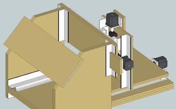
I went to a fixed gantry design for the second iteration, and tried to use Al extrusions throughout, in order to save time and hopefully design a machine that would be easier to get square during assembly. In the end, even with a really good deal on extrusions I was a few hundred dollars over budget because of the large amount of extrusions and hardware that would be required.
So I went back to a MDF-based machine design, and have ended up here:

One part that I am still really in the dark on is the spindle. I realize how backwards that is--in some ways I'm sure it's helpful to think about the part doing the actual material removal first, and then build the design around that piece.
I've only looked briefly, but does anyone have experience with something along these lines: DC 12 48V CNC 300W Spindle Motor Mount Bracket 24V 36V 48V for Engraving Carving | eBay
Or what should I be looking for? I'm hoping to cut wood and foam up through Al, and I'm fine with cutting the Al at a low feed rate on this machine. Any advice is appreciated.
Thanks again,
Daniel
-
01-01-2013, 05:39 PM #18
Registered
- Join Date
- Oct 2004
- Posts
- 590
I think you're going to want to close off the back of your uprights. You've created a giant lever arm back there that currently serves no constructive purpose. Close it off though and the whole structure will stiffen up considerably.
Chris
-
01-01-2013, 06:33 PM #19
Registered
- Join Date
- Jul 2008
- Posts
- 390
I think the whole design could also be improved if the X axis (horizontal one) was recessed back into the fixed gantry and the motor stuck out through a cutout in the side.
The back of the gantry also needs reinforced as OCNC mentioned.
-
01-01-2013, 10:44 PM #20
Registered
- Join Date
- Dec 2012
- Posts
- 0
Thanks Chris -- I made a quick modification to add a piece across the back. Not sure if I'll put it on an angle like this or just something flat across the back and/or top, but I'm guessing this is the idea? Originally Posted by OCNC

Daniel

 Reply With Quote
Similar Threads
-
Burny 5 guidance needed.
By peterro in forum Waterjet General TopicsReplies: 13Last Post: 06-27-2014, 10:37 PM -
Need some guidance on starting out
By AlanDv in forum DIY CNC Router Table MachinesReplies: 2Last Post: 08-20-2011, 05:13 AM -
New to solidworks - Guidance needed please
By -= Keith =- in forum SolidworksReplies: 4Last Post: 08-08-2011, 02:54 AM -
Need a Bit of Guidance on New Build
By adt2 in forum DIY CNC Router Table MachinesReplies: 14Last Post: 06-02-2011, 07:33 PM -
Need Some Guidance in Choosing Components for a 251 Build
By Mr.Chips in forum Gecko DrivesReplies: 1Last Post: 02-27-2009, 07:16 AM
