


Every once in a while, Mach3 will stop and display a "limit" alarm, even though no limits have been tripped. I'm getting some sort of radio interference (RF) but don't know how to solve the problem.
I'm able to duplicate the problem by turning on my TIG welder to try and diagnose the issue.
A bit about my machine;
-Old Hurco converted to Mach3
-using prox switches for limits that activate relays
-Campbell Break-out board
-Larken Viper servo drivers
What I've already tried;
- Set debounce to "0" in Mach
-drove an 8 ft ground rod beside machine and grounded various parts of the mill
-When activating my TIG, the BOB goes nuts and turns my spindle on because it pusates the VFD output relay.
I won't be using my TIG when the machine is on, but I'm just trying to get rid of the annoying "tripping" of the machine in the middle of a program.
Thanks for any help
Results 1 to 20 of 33
-
12-26-2012, 10:41 PM #1
 Registered
- Join Date
- Aug 2008
- Posts
- 303
RF making my machine trip into reset issue !!
The one that dies with the most tools, WINS !!
www.dantechfabricating.com
-
12-28-2012, 06:11 PM #2
Registered


- Join Date
- Oct 2008
- Posts
- 2100
Do you have shielded wire going to your prox switches? Originally Posted by Danno

Is the shield grounded at one central shield grounding point for the machine?
Are your prox switches in an independent cable or do you continue to use the shared cable originally installed in the machine
Does your electrical service entrance and/or remote breaker panel have a good ground?
Now that you have a ground rod according to Hurco you should have your ground strap attached to it from the body of the machine. I'll have to check my manual, but I am pretty sure they specify that the frame of the machine is attached to a ground rod, and not just the electrical ground.
The only other thing I can think of is to see if you can determine which prox/limit switch it is and replace it. Check for any debris that might have gotten into the covers and be resting on a switch possibly making it over sensitive. Check distance and alignment for the same thing. Check for worn or damaged wire that might be causing and intermittent or high resistance short to ground or possibly to a flex conduit that is causing an antenna affect.
Sorry, that's about all I have to suggest, and I am sure you already checked all of that.
At the risk of damaging your machine in the case of a run-a-way you could turn off safe limits.
P.S. I like your assortment of tool holders. I am jealous.Bob La Londe
http://www.YumaBassMan.com
-
12-28-2012, 09:25 PM #3
Gold Member
- Join Date
- Jul 2005
- Posts
- 2415
The debounce number needs to be increased no set to zero. The higher the number the more forgiving of noise it is. All the things listedd can help with noise. The limits and home inputs on the campbell card are isolated so make sure neither wire from the prox sensor is referenced to the local ground. If the prox switches use external power make sure it too is "floating" and it's ground only goes tot he input common on the Campbell card. In short the inputs should NOT share a common ground with the machine ground or you just put any noise there onto the inputs
that circuit when hooked up right is very noise immune and works around plasam , TIG and other nasty sources.
-
12-28-2012, 10:41 PM #4
Registered
- Join Date
- Oct 2008
- Posts
- 2100
I didn't suggest the circuit of the prox should be grounded. I said the shield should be grounded to a single common ground with all other shields and earth ground. The reason I specified single common ground point for shields is to reduce the liklihood of creating a ground loop. Good info about the debounce. I did not know that. Originally Posted by Torchhead
Bob La Londe
http://www.YumaBassMan.com
-
12-28-2012, 10:53 PM #5
Community Moderator
- Join Date
- Dec 2003
- Posts
- 24220
Keep in mind your PC M.B. Power Supply common is at ground potential, on a TIG/Plasma it is important to make sure everything is at Earth ground potential.
If everything is earth ground bonded back to a central star point, it eliminates the condition every body quotes, 'ground loops'.
The technique is called equi-potential bonding, I have posted a Siemens PDF on it many times.
With Isolating any supplies from earth ground, they are still prone to inductive or capacitive coupling from noise inducing equipment.
Al.CNC, Mechatronics Integration and Custom Machine Design
“Logic will get you from A to B. Imagination will take you everywhere.”
Albert E.
-
12-29-2012, 06:37 AM #6
Registered
- Join Date
- Aug 2008
- Posts
- 303
Thanks for the tips;
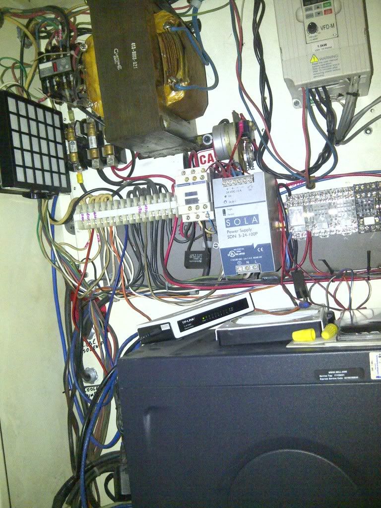
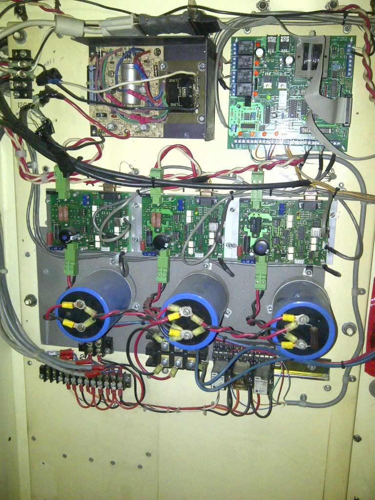
I've enclose a couple of pictures of my electronic enclosures in case you see something that is not right. My prox switches activate relays, and the relays give the BOB the signals. When my machine trips, the relays do not activate, even though it says "LIMIT TRIPPED" on my Mach screen.
I disconnected the 25 pin from the BOB, and activated my TIG. The BOB went nuts by violently switching the VFD output relay. It kept on doing it even after I stopped the TIG, and the only way I could get the BOB to get back to normal was by switching power.
It's very difficult to explain what is happening by typing, so in the next few days I will make a short video and post the link. I would really like to get rid of this glitch. This is really the only issue I've had, and other than that, it's been an excellent machine.
The top picture is a metal cabinet which sit directly above the cabinet that houses my servo drives and BOB ( 2nd picture )
I always thought that if the debounce number was set to zero, that it would be less prone to noise. Hmmm..
I'm sort of confused about "floating ground" , "ground loops" etc.. I was told that I should try grounding the negative output of my DC power supplies ( I have 2, one 12v, and one 24). I think that short video may clarify things.
Thanks guys, I really appreciate your input.
Dan
 The one that dies with the most tools, WINS !!
www.dantechfabricating.com
-
12-29-2012, 07:54 AM #7
Gold Member
- Join Date
- May 2005
- Posts
- 3920
Some prox switches are very sensitive.
At work we have one prox that can be tripped by a cell phone or two way radio. That is one prox out of maybe a hundred. With cell phones you need to realize they are always on maintaining a connection to the local cell tower. So you don't even need to be using the cell, all the cell phone has to do is a maintenance transmission to that local tower. I'd try leaving the cell phone outside of the shop and see what happens.
As far as the welder goes, I'm not surprised at all that, that would cause you issues. Welders put out a lot of energy both conducted and radiated. If you can avoid running the welder while running the CNC that would be the easy solution. If not and your shielding and termination techniques are good then you may have to look for prox switches with higher immunity to RF and weld fields. There isn't a lot that can be done about excessive sensitive prox switches other than to replace them with something less sensitive.
As has already been mentioned grounding and shielding techniques play an important part in enhancing a machines immunity to RF noise. Right now we aren't certain what is tripping your machine. That is is the prox switch toggling due to RF interference or is the energy getting to the electronics some other way. RF interference isn't likely to pull in a relay on its own, so it it isn't a prox then the interference is getting to the electronics via another path.
-
12-29-2012, 08:21 AM #8
Gold Member
- Join Date
- May 2005
- Posts
- 3920
How certain are you that the relays have not activated? All you really need is a fast glitch. As such you may not see the relay activate. Originally Posted by Danno
That really isn't a surprise, welders can mess up otherwise stable electronic systems from a considerable distance. Since you have indicated that the problem occurs without the welder running then we can discount this behavior.
I disconnected the 25 pin from the BOB, and activated my TIG. The BOB went nuts by violently switching the VFD output relay. It kept on doing it even after I stopped the TIG, and the only way I could get the BOB to get back to normal was by switching power.
These things can be extremely frustrating and sometimes it is hard to determine sources of interference. One thing to do is to make sure every DC relay in the machine has a snubbing diode across the coil, AC relays should have a metal Oxide varistor and a high voltage RC circuit across the coil. Your panel layout bothers me a bit as it appears that there is some signaling/control wiring running along with power wiring which MAY be a problem.It's very difficult to explain what is happening by typing, so in the next few days I will make a short video and post the link. I would really like to get rid of this glitch. This is really the only issue I've had, and other than that, it's been an excellent machine.
I will try to take a shot at ground loops. If you buy the idea that current will flow in shield wires and the like you can imagine that if you have a cable with a shield grounded at both ends then you have created a loop half of which is the shield in the cable and the rest the structure that you are grounded to. You literally can have currents flow in that loop instead of going to ground. You break the loop by leaving the shield disconnected at one end.The top picture is a metal cabinet which sit directly above the cabinet that houses my servo drives and BOB ( 2nd picture )
I always thought that if the debounce number was set to zero, that it would be less prone to noise. Hmmm..
I'm sort of confused about "floating ground" , "ground loops" etc.. I was told that I should try grounding the negative output of my DC power supplies ( I have 2, one 12v, and one 24). I think that short video may clarify things.
Thanks guys, I really appreciate your input.
Dan
Now to take this a step further you have a mass of cables with shields that can also create loops. To avoid this what is recommend end is what is called a star ground arrangement. Here all shield or ground connections terminate at one place in the machines panel box. Often this is a copper or brass plate with a bunch of holes drilled in it. This prevents the accidental creation of ground loops in the process of wiring the machine. The term star comes from all the ground and shield wires coming back to that common point creating a bunch of arms for the star.
Running out of battery power, hope this is enough to get you started.
-
12-29-2012, 09:19 AM #9
Registered
- Join Date
- Jan 2011
- Posts
- 188
if the bob senses a limit signal from an open relay
and it goes crazy with the db25 unplugged
make sure the inputs are not left floating, they should be pulled high or low, or else they can fluctuate between high and low in response to environmental electromagnetic interferance (emi) and 'go crazy'
false emi input signals are usually short duration (microseconds), so having a debounce delay of a few milliseconds filters out signals with shorter duration such as emi
with no debounce delay there is nothing stopping mach from responding to every emi induced voltage shift which can be thousands per second
just unhook the limit signal relay to rule it out, and if you still get false limit signals on the open wire then it must be a floating input (needs to be pulled high or low) or the bob or something further upstream is faulty
along with having proper grounding and shielding, you must also avoid having floating inputs, and do use debounce delay,www.signtorch.com
-
12-29-2012, 05:56 PM #10
Member
- Join Date
- Jun 2007
- Posts
- 3757

Have the relay contacts OPEN when a limit is hit.
1. The NC position of relay stop floating inputs picking up stuff. Nice antennas when open?
2. If a limit wire breaks during operation, it will just continue like nothing happened, and not trip on limit.
3. Debounce value around 1000-2000. Wants to be about 1 mains cycle or more.
4. Your ribbon cable is running parallel to the red/white twisted cable. It is also right on top of a power transformer!
Try to separate them and see if that makes a difference.
5. Where is your common star ground point? I see various cables under multiple bolts.
Temporarily disconnect ALL of them and tie them to a common point and to ONE ground point. IMPORTANT!!
There should ideally only be ONE ground point to the chassis for the whole machine.
6. What are the two yellow wires going to middle lower edge of the BOB? Might be a nice antenna.
If after converting to NC operation you still have a problem then disconnect limit wires at BOB and bridge them with links and see if it still trips.
If so it is getting into the BOB elsewhere. Does the BOB have a micro?
The wire to the relays should have a shield, only connected at the BOB end.Super X3. 3600rpm. Sheridan 6"x24" Lathe + more. Three ways to fix things: The right way, the other way, and maybe your way, which is possibly a faster wrong way.
-
12-29-2012, 06:19 PM #11
Registered
- Join Date
- Aug 2008
- Posts
- 303
Thanks Originally Posted by neilw20
The one that dies with the most tools, WINS !!
www.dantechfabricating.com
-
12-29-2012, 06:30 PM #12
Member
- Join Date
- Jun 2007
- Posts
- 3757
2. don't worry. 1 explains you have it correct.
5. I looked inside an OKUMA lathe and there was 1 2" bundle of greens coming from multiple places and enclosures going to a single point ground.
A micro? It is possibly one of the chips on the BOB. What make and model is the BOB?
Before you bother shielding the wires, try the bridge connection test at the BOB.
If it is still no good then a shield might not be needed.Super X3. 3600rpm. Sheridan 6"x24" Lathe + more. Three ways to fix things: The right way, the other way, and maybe your way, which is possibly a faster wrong way.
-
12-29-2012, 06:34 PM #13
Community Moderator
- Join Date
- Dec 2003
- Posts
- 24220
I do not see a star point ground either?
If you have two cabinets, then they should be bonded from star point to second cabinet back plate ground point.
A Ground loop is where there exists a potential difference between any given motor frame, enclosure, metallic machine frame etc.
It explains it in depth in the PDF.
Now there a preference to equi-potential bonding technique and this allows the grounding of both ends of the shielded cable.
See Ch6.
http://www.automation.siemens.com/do.../emv_r.pdf?p=1
Al.CNC, Mechatronics Integration and Custom Machine Design
“Logic will get you from A to B. Imagination will take you everywhere.”
Albert E.
-
12-29-2012, 06:34 PM #14
Registered
- Join Date
- Aug 2008
- Posts
- 303
I appreciate the help Originally Posted by wizard
The one that dies with the most tools, WINS !!
www.dantechfabricating.com
-
12-29-2012, 10:35 PM #15
Gold Member
- Join Date
- May 2005
- Posts
- 3920
There are many possibilities here.
No problem. Originally Posted by Danno
This was years ago but I worked in a place that implemented some really old Bandit controllers and other hardware to make custom diamond turning lathes. Great little machines but we had one problem that seemed to take forever to resolve. One or more axis would loose position over time, this wasn't thermal growth or any of the other things that can send you down the wrong track. Eventually, many weeks in fact, we found out that relays inside the packaged spindle drive where causing the problem. One of the lathes was put in a loop to cycle the spindle on and off, after x number of cycles you could see a position error. The point of this is that even if you are a team of engineers and technicians sometimes the root cause is elusive.
As for relays and noise control I'm linking here because others can explain it better. One document: http://www.sprecherschuh.com/library...ession_109.pdf another document here is better written: http://relays.te.com/appnotes/app_pdfs/13c3311.pdf this one touches upon grounding: http://www.ctc-control.com/customer/...TechNote26.pdf. There are probably hundreds of such documents on the Internet because it is a problem that never goes away. Even established machine builders run into problems in the field after taking the established techniques into account. As the one document above highlights there are a few methods that allow one to control the noise generated by a relay turning off. For DC relays I often use the reverse biased diode technique. As noted this can drastically impact switching time. The diode + Zener combo suggested can in all likely hood be replaced with a special purpose suppression diode these days.
Here is the sticky ball of wax, even though transient suppression is needed on the relays in your system they may or may not be the source of your issues. So you could properly install the transient protection and still have the same issue after you are done. The other thing to realize is that the relays generally can't cause a problem if they aren't switching states. So if this happens when nothing is changing states on the machine then you likely have more hunting to do. Close observation of what happens can help you zero in on the cause, especially if the failure happens in conjunction with a specific operation.
I'm not familiar with the BOB you are using, but many of these are not as robustly made as their industrial counter parts. Someone has already indicated that you may need pull up resistors to clamp inputs to a reliable state. That may be an issue that would allow RF interference to mess with an input. Having not used the board I can't help beyond suggesting following manufactures instructions for installation.
This brings us to another reality, electronics can be sensitive to conducted interference such as transients conducted on wires and RF or radiated interference. A TIG welder can generate both in very energy intensive ways. As such you may be triggering an entirely different method of failure with the welder as opposed to the failure you get normally running the nachine. Focusing on trying to fix the issue caused by the welder may or may not lead to the run time issue.
One thing to do here is to make sure RF radiating devices are no where near your machine when it is operating. That means cell phones, cordless phones, WiFi equipment or ports, HAM gear, old radios and anything else that transmits. All it takes is one prox, a loose input or an un shielded wire acting as an antenna, to cause a false trigger. Since these devices can and often do transmit independent of anything you are doing it makes debug a problem. If you remove them from the area or turn them off and the problem goes away then you at least somewhat know the problem is RF activated.
There is always the possibility of a flakey BOB right out of the box. I don't believe this is the issue yet as you have to resolve the wiring issues first. As to resolving those issues don't be surprised to find yourself remounting some components to better control the runs of control and power wiring.
I hope this helps a bit. These problems are difficult to deal with in person much less remotely. Often you end up scratching your head until a correlation is found.
-
12-29-2012, 11:31 PM #16
Registered
- Join Date
- Aug 2008
- Posts
- 303
Thanks Wizard !!
I totally agree that using my TIG to trigger a fault may be sending me down the wrong path. Unfortunatelly, the machine tripping on it's own is not a common occurance which makes it all that more difficult to track down the root cause. You, as well as others here have given me a lot to work with, and hopefully (time permitting) I will have a clearer idea of the issue in a week or so.
The reason I built this machine was to take me out of my comfort zone which is machining, and to teach myself something I knew nothing about. It has definitely done that !! :-)
DanThe one that dies with the most tools, WINS !!
www.dantechfabricating.com
-
12-29-2012, 11:38 PM #17
Member
- Join Date
- Jun 2007
- Posts
- 3757
Some time back I remember I had a problem turning on a flouro light and my machine coming to an instant stop.
After much careful checking it was found to be marginal level to the parallel port.
Not all ports are the same.
I made a buffer card to correct the levels as a quick fix.
Replacing the parallel port (on the PC card) with a PCI card fixed the problem.
The driven signal from the CNC was marginal and need a well defined high AND well defined LOW state.
If I used small enough pullup resistor, the CNC circuit drive level became marginal and could not pull low enough.
Typical of an input on a small micro (on the motherboard) that requires a well defined state for one machine cycle of the micro to be recognized correctly.
The port just not match the standards for a parallel port.Super X3. 3600rpm. Sheridan 6"x24" Lathe + more. Three ways to fix things: The right way, the other way, and maybe your way, which is possibly a faster wrong way.
-
12-30-2012, 12:46 AM #18
Community Moderator
- Join Date
- Dec 2003
- Posts
- 24220
The method of choice as to common ground or total isolation is one of personal preferential choice. Originally Posted by Danno
Just as a point of reference, for what it is worth.
In the 20+ years of integrating Commercial CNC as well as designing PC based systems (includes pre-Mach), I have always used the common earth ground method for all supplies, using opto-isolation has just been for voltage transition from one level or type to another, or used 2n7000 or ULN2803 to go from 5v to 24vdc.
As previously mentioned, your PC P.S. is at ground reference already.
Over this period I have never had an issue with noise problems, and this is in some of the harshest industrial environments.
Al.CNC, Mechatronics Integration and Custom Machine Design
“Logic will get you from A to B. Imagination will take you everywhere.”
Albert E.
-
12-30-2012, 06:34 PM #19
Registered
- Join Date
- Aug 2008
- Posts
- 303
This morning I changed the debounce values (debouce interval and index debouce) both to 1500.
I activated my TIG and Mach did not go into reset, but my BOB still did not like it because I could hear it's relays clicking and my spindle started to turn.
There's something else I forgot to mention !! I use a mouse as well as a "touch monitor". When Mach goes into "reset" after I turn on the TIG, the touch screen will still work, but my mouse will be dead. The only way to be able to use my mouse again is by re-booting the computer(PC)
Someone asked what kind of BOB I use, and it's the Campbell All-In-One board.The one that dies with the most tools, WINS !!
www.dantechfabricating.com
-
12-30-2012, 07:01 PM #20
Community Moderator
- Join Date
- Dec 2003
- Posts
- 24220
Do you have your PC fed off of a separate socket, or is the AC coming from the enclosure source?
Al.CNC, Mechatronics Integration and Custom Machine Design
“Logic will get you from A to B. Imagination will take you everywhere.”
Albert E.

 Reply With Quote
Similar Threads
-
ERROR 449 Cant reset machine
By stringer in forum Uncategorised MetalWorking MachinesReplies: 1Last Post: 05-03-2012, 11:48 PM -
Fanuc 3T machine alarm reset
By TDCMS in forum FanucReplies: 0Last Post: 04-10-2012, 04:33 PM -
Machine Hours Reset???
By WGJ in forum Haas MillsReplies: 17Last Post: 01-26-2012, 05:38 PM -
Reset offset after turning machine off?
By behindpropeller in forum Haas MillsReplies: 1Last Post: 11-23-2010, 10:33 PM -
machine reset parameter
By priyo in forum Mazak, Mitsubishi, MazatrolReplies: 1Last Post: 11-28-2007, 07:45 AM
