


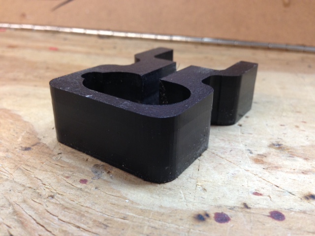
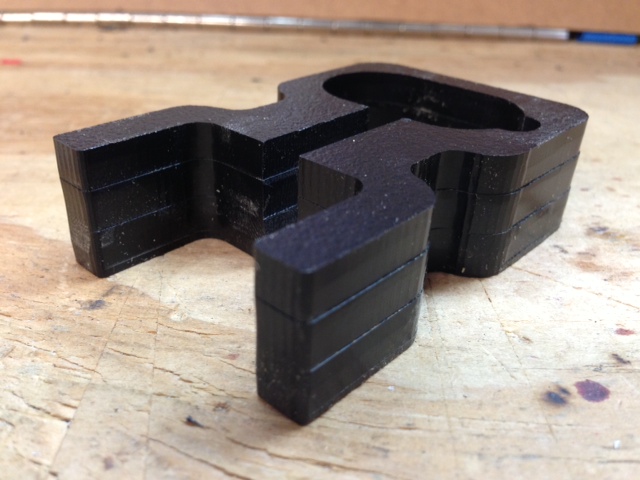
So I cant figure out why my router is cutting my pieces like this everytime... on happens on the Right and Bottom sides. You can see each pass decently well. My machines seems very tight. But still you can see the depth cuts. im not even sure what this "problem" is called. check out the pics and let me know what you think. One side is the clean side, one is the messed up side. Please help!!!
Results 1 to 20 of 21
-
02-02-2013, 05:19 AM #1
 Registered
- Join Date
- Apr 2011
- Posts
- 63
 See if you can figure this one out!
-
02-02-2013, 06:47 AM #2
Registered
- Join Date
- Jul 2009
- Posts
- 690
If two sides are at 90º relative to the surface of the material and the other two are in an angle (which would cause offset edges like in the pictures) it might be bad tramming, check that both the Z rails and the bit are perfectly perpendicular to the X/Y plane.
http://www.build.cl
-
02-02-2013, 07:28 AM #3
Registered
- Join Date
- Aug 2011
- Posts
- 999
I can not see what the size of the part may be. But it looks like the pass depth is rather deep and from the little scallops the feed rate may be rather high. What are your machining parameters?
If machining deep with high speed, especially with a slim bit, that may just be flexing of the bit or the machine.
If you can not reduce the speed due to melting you may try the following:
- reduce pass depth
- machine first in climb mode (leaves more material) then run the same path in conventional mode to clean it up.
-
02-02-2013, 01:56 PM #4
Community Moderator
- Join Date
- Mar 2003
- Posts
- 35538
I vote for the out of tram spindle.
Gerry
UCCNC 2017 Screenset
http://www.thecncwoodworker.com/2017.html
Mach3 2010 Screenset
http://www.thecncwoodworker.com/2010.html
JointCAM - CNC Dovetails & Box Joints
http://www.g-forcecnc.com/jointcam.html
(Note: The opinions expressed in this post are my own and are not necessarily those of CNCzone and its management)
-
02-02-2013, 02:26 PM #5
Registered
- Join Date
- Sep 2010
- Posts
- 528
It is almost definitely spindle tram. I was having the same problem.
Build yourself a tram indicator like the in the picture. Surface a piece of plastic with a large bit. You'll notice scallops or ridges on the surface. Then swing the indicator in a circle. You might be surprised at the results.
I have seen an unbelievable improvement in my surface finish since I have trammed my spindle.James Harvey
Harvey Development Corp.
www.Harvey-Development.com
36" x 52" CNC Router
ULS-25E 12" x 24" Laser Engraver
-
02-02-2013, 02:32 PM #6
Member
- Join Date
- May 2012
- Posts
- 231
Use a square on the sides of the part to check the steps of the cut. See if they are beveled cut. If so then you have your answer. Like the others said tram setting looks like the answer.
-
02-02-2013, 03:06 PM #7
Registered
- Join Date
- Apr 2011
- Posts
- 63
And I almost bought a dial indicator yesterday! I'll go back and pick one up tommorow. Did you make the mount to go in the spindle?
-
02-02-2013, 03:07 PM #8
Registered
- Join Date
- Apr 2011
- Posts
- 63
Also what exactly do I need to do to "tram" my spindle?
-
02-02-2013, 03:13 PM #9
Member
- Join Date
- Jan 2007
- Posts
- 1795
ed
harvey posted a picture
that picture says everything
mount any way an indicator on your spindle
as you turn spindle around by hand, and indicator shows difference, that difference need to be eliminated..
-
02-02-2013, 03:24 PM #10
Gold Member
- Join Date
- Apr 2009
- Posts
- 5516
Before you tram the spindle, you need to make sure your Z axis is also trammed; meaning it moves up and down perfectly square in both directions. Then and only then can you tram the spindle itself.
-
02-02-2013, 08:41 PM #11
Registered
- Join Date
- Feb 2004
- Posts
- 304
^ What he said. That's just as important as having your spindle trammed.
-
02-02-2013, 08:57 PM #12
Registered
- Join Date
- Apr 2011
- Posts
- 63
And the correct way to do this? Originally Posted by louieatienza

-
02-02-2013, 10:24 PM #13
Registered
- Join Date
- Jun 2011
- Posts
- 72
Ed3XP
When you have an out of tram spindle, you will get the stepped edges on one side only, because the end mill is not vertical.
One side (the stepped side) has the tip of the end mill closer to the material than the top of the cutting edge.
On the other side, the top of the cutting edge is closer than the tip, and keeps cutting the full edge on the way down and keeps it smooth.
Given that you have this piece stepped edge on 2 sides, it indicates that you are out of tram in both the x and y directions.
You have stepped edges on the right and bottom edges, so your spindle needs to be moved
1. anti clockwise when viewed from the bottom side (to remove the steps on the right edge)
2.clockwise when viewed from the right side (to remove the steps on the bottom edge).
I can't tell by looking at your photo whether the z-axis or the spindle mount is out, so you will need to check/adjust both.
To tram the z axis you can do the following (there are other ways too).
1. surface your spoilboard
2. put your indicator in the spindle (or otherwise mounted to the moving part of your z-axis), with the indicator shaft horizontal.
3. mount a square to the spoilboard in the x+/x- direction
4. with the dial indicator facing one way only, run the z axis up and down.
5. shim/adjust the z axis mounts until any difference between the top and bottom is removed.
6. turn the dial indicator 90 degrees in the spindle & turn the square 90 degrees on the spoilboard in the y+/y- direction.
7. repeat 4 and 5.
Once you have trammed the z-axis, then you can tram your spindle by adjusting the spindle mounts.
1. lower the spindle to any given level such that your indicator (with the indicator shaft vertical) is giving you a reading on the spoilboard (or a flat sheet placed on the spoilboard). Position on the x+ side of the spindle. zero
2. turn the spindle 180 degrees (x- side of spindle) and read.
3. shim/adjust your mount so that the difference between the 2 readings is reduced to zero (or as close as possible).
4. repeat 1,2&3 in the other orientation (y+/y-).
You'll have to work out what you can adjust and/or shim. This depends on your machine.
Hope that helps.
Paul
-
02-02-2013, 11:39 PM #14
Registered
- Join Date
- Sep 2010
- Posts
- 528
It depends on how your Z axis is constructed. The idea is that the rails that guide your Z up and down are exactly perpendicular to your X axis and Y axis travel. This allows the endmill to move up and down instead of an angle. Originally Posted by Ed3XP
I used shims under the V-bearings that guide my Z.
If you post a picture of your Z we can give you some ideas.James Harvey
Harvey Development Corp.
www.Harvey-Development.com
36" x 52" CNC Router
ULS-25E 12" x 24" Laser Engraver
-
02-02-2013, 11:49 PM #15
Registered
- Join Date
- Apr 2011
- Posts
- 63
Thanks guys! Love this! Will try it tommorow!
-
02-04-2013, 12:57 PM #16
Registered
- Join Date
- Oct 2012
- Posts
- 28
Excellent information. I am just about to setup my first machine for PCB milling and knowing the right way to get everything square is so important. Originally Posted by bushwakka
-
02-05-2013, 03:23 AM #17
Registered
- Join Date
- Apr 2011
- Posts
- 63
So here is what I got....
On the X axis.. Zero'd on the Left side, and got like .18" on the right...
On the Y axis.. Zero'd on the back side, and got like .08" on the front.
Closest I could get was on the X.. Left 0 - right 0.016" and Y axis was back-0 front was -0.009
and the Z axis was 0 lifted and 0.012 all the way down.
Are these numbers tolerable? I ran the pieces again and got the same results though... how close are you guys getting?
-
02-05-2013, 04:42 PM #18
Registered
- Join Date
- Apr 2007
- Posts
- 74
You really want everything less than 0.001"
If you were at 0.003 - that should be fine (machine might flex that much).
When you tram, ideal is a smooth aluminum plate. Sand down any fuzzy on your waste board to get the plate flat. Measure off the plate.
Looks like you have have 4" between spindle and dial indicator. 0.016" error is sin-1 0.016/4 = 1/4 of a degree.
You might need to elongate the holes on the Z to get more adjustment, and shim to get the for/aft resolved. Spending an afternoon doing this will pay off in the long run.
-
02-05-2013, 05:46 PM #19
Member
- Join Date
- Jan 2007
- Posts
- 1795
the 3rd and 4th picture , you measure nothing..
that way you cant measure if the cariiage in an angle..
your cariiage is on 4 roller.. very possible they are not on position somehow..
-
02-06-2013, 08:48 AM #20
Registered
- Join Date
- Jun 2011
- Posts
- 72
As Victor said, in photos 3 and 4 it doesn't appear that you are actually measuring anything of value. All you are checking is that the side of the aluminium plate is parallel to the moving part of the linear slide of the z-axis.
To measure something of value, you need to have the dial indicator mounted to the z-axis carriage so that it moves up and down, and then you need to indicate off a surface that is square to the baseboard.
I can see in your spoilboard that things are not quite right. You should be able to tell with you fingernail which way you are out (depending on which direction catches your nail)
Surface your spoilboard before your start. The lumps in the mdf from screwholes are probably enough to cause issues. Then put a piece of flat sheet (aluminium plate or some 3/4" mdf) down and indicate of that. If you indicate directly off the spoilboard, the uneven surface could influence your readings.
RoundRockTom, the error is half your calculation because there is 0.016 difference on the diameter (not the radius), so over 8 inches of circle.
Paul.

 Reply With Quote
Similar Threads
-
I Still Can't Figure It Out
By MetalShavings in forum SprutCAMReplies: 9Last Post: 11-22-2011, 04:01 PM -
Help me figure out if this is possible.
By Joezx10r in forum Benchtop MachinesReplies: 2Last Post: 09-23-2009, 12:29 PM -
trying to figure out what i want.
By smooth72 in forum SmithyReplies: 21Last Post: 08-25-2009, 06:26 PM -
Can't seem to figure this out.
By cjdavis618 in forum Uncategorised CAD DiscussionReplies: 10Last Post: 05-16-2009, 03:16 PM -
Can't figure something out???
By BTC 111 in forum MastercamReplies: 6Last Post: 02-03-2009, 12:42 AM
