


I sent you the phase 3 update, these questions are covered in detail in the update along with cad drawings for a nut removal tool and how to use it.Originally Posted by redpiperbob

Hoss
Thread: Andrew's G07040 build
Results 141 to 160 of 241
-
07-21-2014, 08:04 PM #141
 Member
- Join Date
- Apr 2006
- Posts
- 8159
Re: Andrew's G07040 build
http://www.hossmachine.info - Gosh, you've... really got some nice toys here. - Roy Batty -- http://www.g0704.com - http://www.bf20.com - http://www.g0602.com
-
07-22-2014, 06:19 AM #142
Registered
- Join Date
- Sep 2006
- Posts
- 37
Re: Andrew's G07040 build
Hi Hos
thanks for that
Bob
-
07-24-2014, 02:30 PM #143
Registered
- Join Date
- Sep 2012
- Posts
- 323
Re: Andrew's G07040 build
Making some progress on the power draw bar.
following LacL design with a few changes, thanks again for the free plans!!!!:cheers:
Andrew
-
08-14-2014, 09:57 AM #144
Registered
- Join Date
- Sep 2012
- Posts
- 323
Re: Andrew's G07040 build
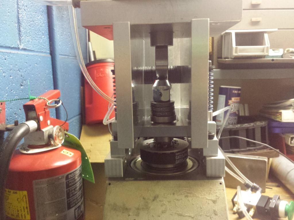
got the PDB done but then had to change the design to keep the pressure off the quill
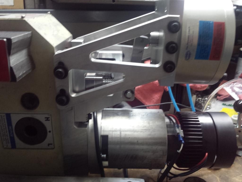
redesign
Not the best but works and I'm going to run with it for a while.
Ordered some TTS style tool holders the China via Ebay. 6 x ER 20, 2 x ER 25 and 2 X ER32. They will have the grove for ans ATC if I ever decide to go the route. $218 total shipped. Also ordered a manual oil pump and 5 way push button valve for the PDB.
Just pulled apart my make shift electronics board to start laying out my control box.
First mock up:
I have to remove all the brackets so I can make a main board to mount everything to
Need to keep this moving! :wee:
Andrew
-
08-24-2014, 12:37 PM #145
Registered
- Join Date
- Sep 2012
- Posts
- 323
Re: Andrew's G07040 build
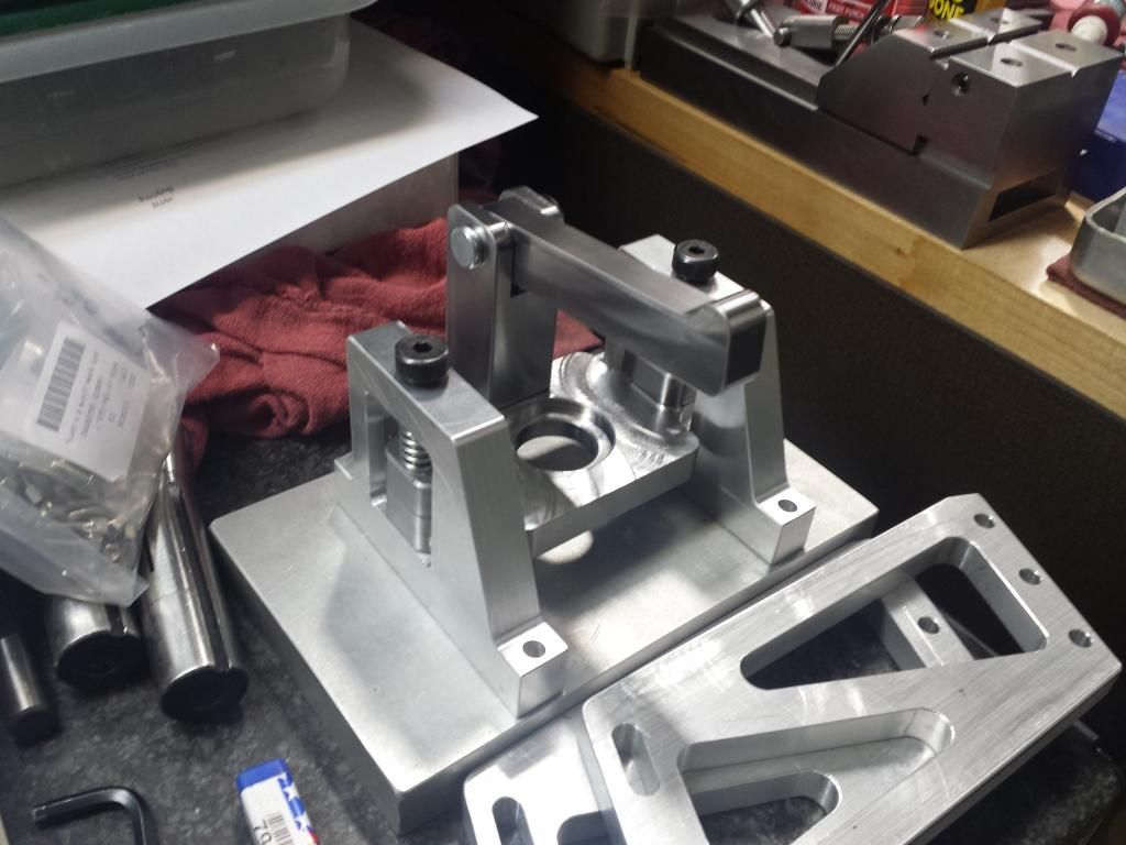
Well I redesigned my redesign of the redesign of LacL PDB. Now it puts no pressure on the spindle bearing, like the last redesign, but is also balanced!
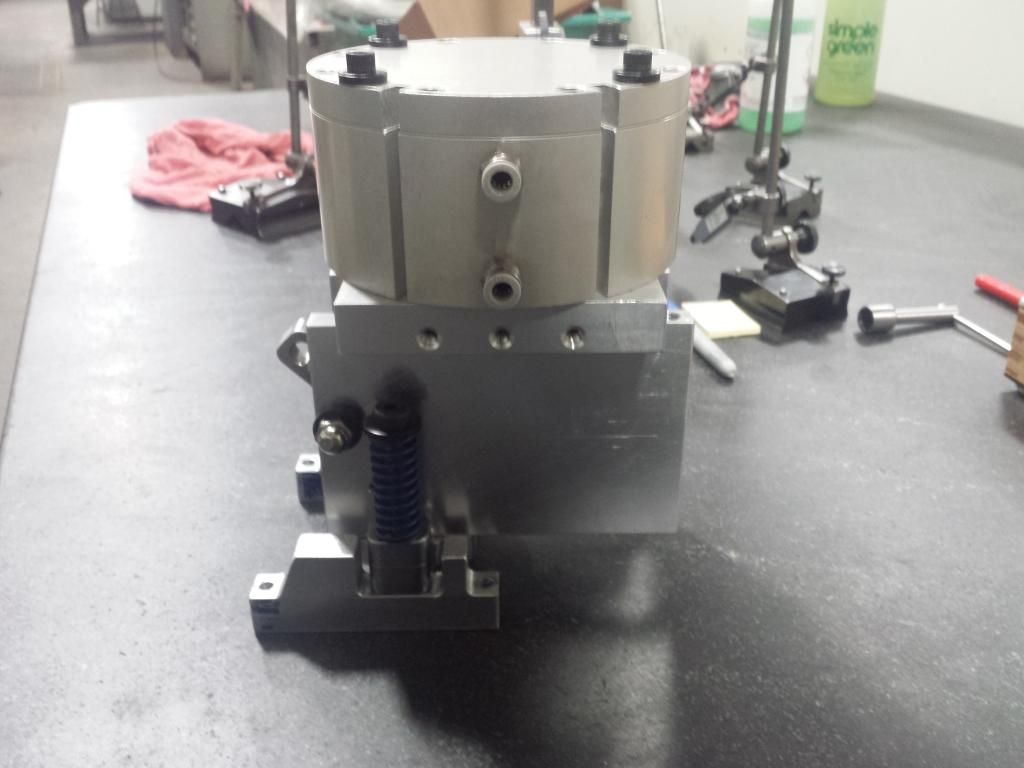
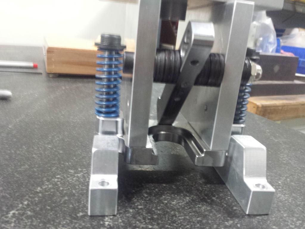
So I moved the cylinder closer to the spindle, put the pivot point in the up rights like Hoss' new PDB 3. I kept the same 2.85:1 ration.
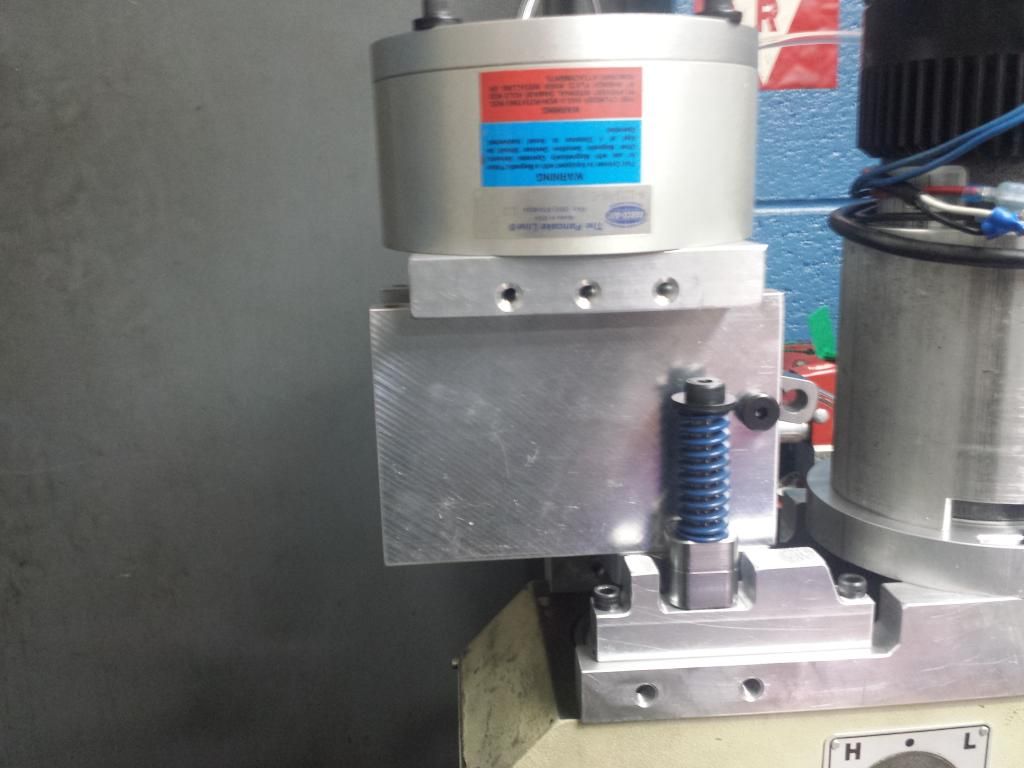
Its not the prettiest but it works as I want it to. I may put some spacers under the lift plate to increase the gap between the lever and the drawbar.
Also got my tts style holders from China
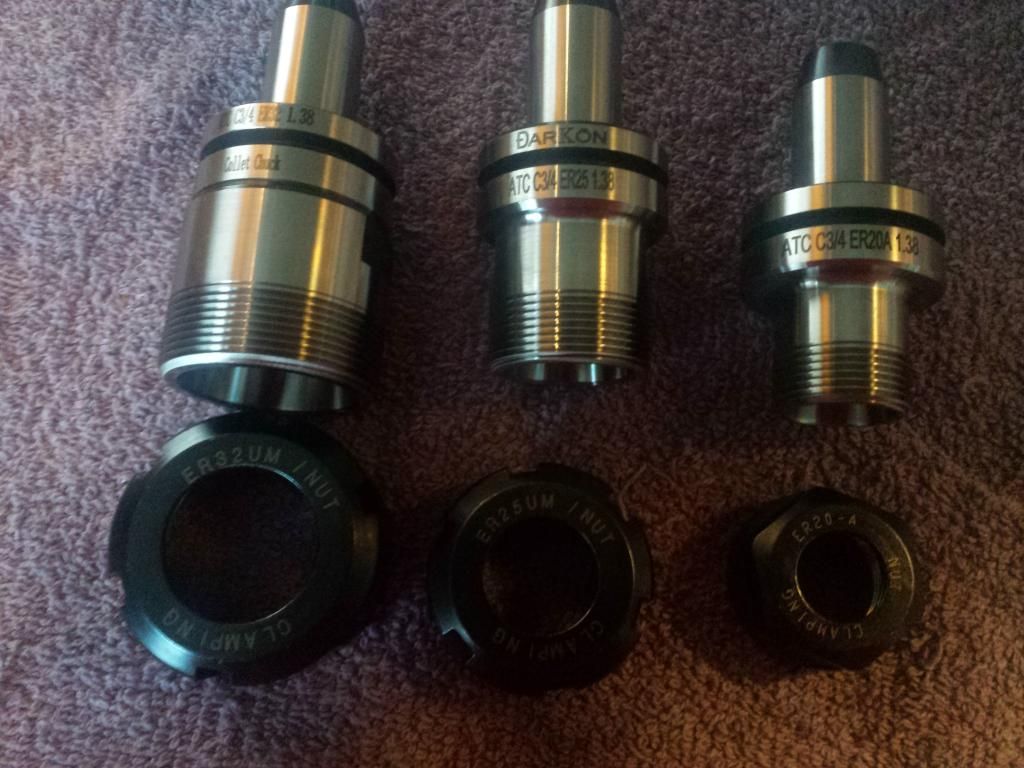
Andrew
-
08-25-2014, 04:29 AM #146
Registered
- Join Date
- Jan 2008
- Posts
- 1529
Re: Andrew's G07040 build
Andrew,
Nice work.
Do you have drawings?
I'm thinking of trying a manual version - lever operated.
Cheers,
Nick7xCNC.com - CNC info for the minilathe (7x10, 7x12, 7x14, 7x16)
-
08-25-2014, 07:26 AM #147
Registered
- Join Date
- Sep 2012
- Posts
- 323
Re: Andrew's G07040 build
I have some very confusing drawings I made on the fly for this. If I were to post them as is most would look at it like Originally Posted by pippin88

If you want to do a manual one with a lever, I would just follow LacL's original design. You would need the guide brackets, lift plate, top hat, clevis base and a lever for your hand. Along with the needed purchased items.
I think a manual version would put any extra force on the spindle bearings thought?
Andrew
-
08-25-2014, 12:59 PM #148
Registered
- Join Date
- Jan 2008
- Posts
- 1529
Re: Andrew's G07040 build
A manual one can work just the same as yours, but just extend the lever a long way in front instead of having an air cylinder.
7xCNC.com - CNC info for the minilathe (7x10, 7x12, 7x14, 7x16)
-
08-25-2014, 02:46 PM #149
Registered
- Join Date
- Sep 2012
- Posts
- 323
Re: Andrew's G07040 build
I get what you are saying. But you will be anchored to the ground (you being the mechanical device applying the force) . So just like any other PDB that is attached directly to the machine, any extra force will be applied to the spindle bearings.
in my case it was pushing the quill out of the head.
I'm not saying it won't work, just saying what will more than likely happen.
Andrew
-
08-26-2014, 02:58 PM #150
Registered
- Join Date
- Sep 2012
- Posts
- 323
 Grounding shielded cables?
So I have shielded cables for my steppers. I am thinking of using the GX-16 style connectors on my control box. Can I ground the shielding to these metal plugs?
Here is the cable I am using and here are the 4 pin connectors I want to use.
Or maybe I should go for 5 pin connectors and use the 5th pin for grounding?
Please chime in o great forum co-members, I need someone with know on wiring. Still very much a noob on this topic!
Thanks,
Andrew
-
09-05-2014, 08:14 AM #151
Registered
- Join Date
- Sep 2012
- Posts
- 323
Re: Andrew's G07040 build
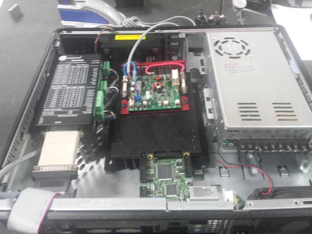
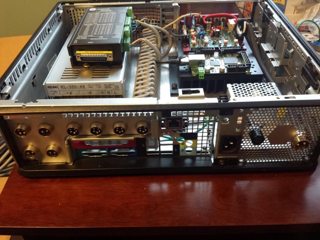
Got the electronics fastened down to the base plate tonight.
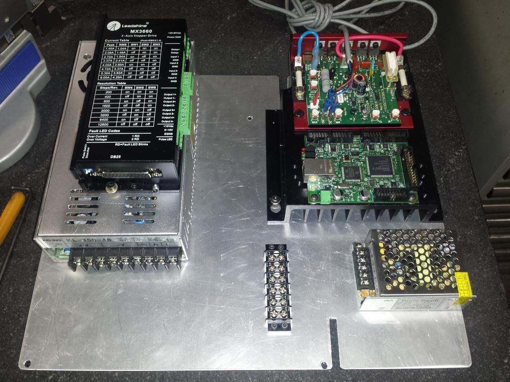
And it in the computer case I sourced from work.
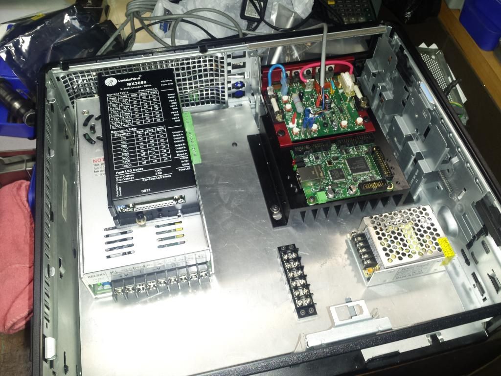
It's kind of a snug fit but it all clears.
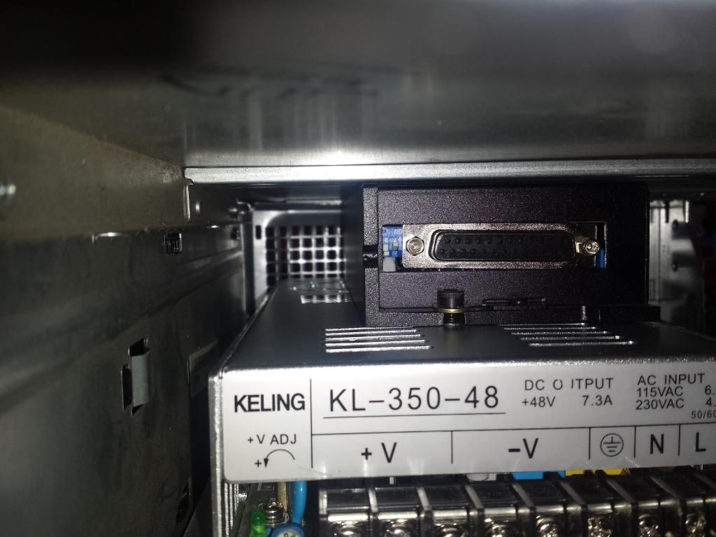
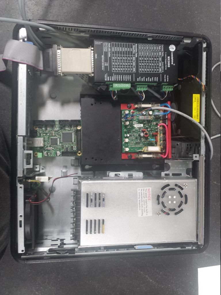
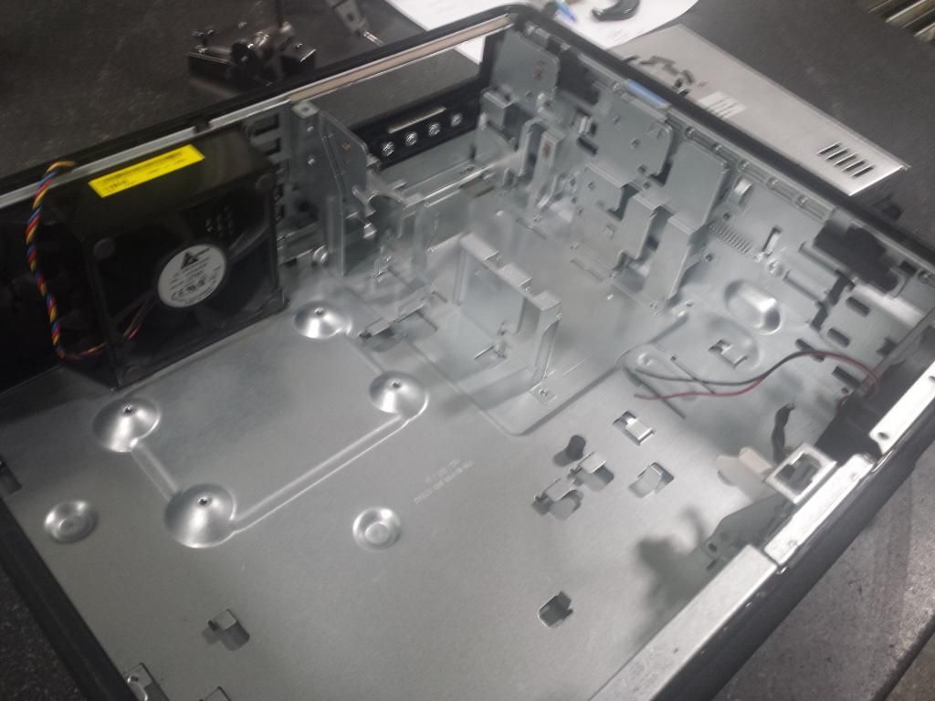
I plan to run a cable duct between the big PSU and kbmm heat sink toward the terminal bar and then a run in front of the big PSU. in front of the big PSU is where all the motor and limit connectors will be. Power coming into the box by the small PSU. I took the computers PSU apart to reuse the back portion .
Speaking of which, why is very prong connected to each other in the pic below? I can just rip all this stuff of right?
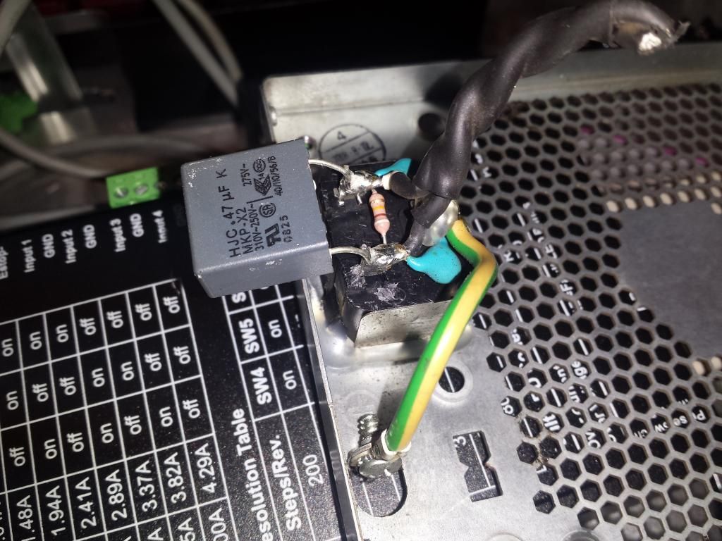
Andrew
-
09-06-2014, 12:25 AM #152
Registered

- Join Date
- Aug 2005
- Posts
- 1091
Re: Andrew's G07040 build
Hi,
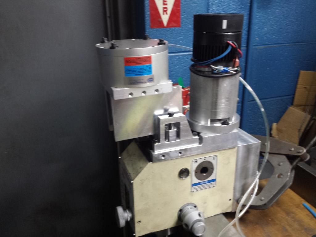
A couple of issues you may (or may not) experience with your setup.
1. You have your stepper drive mounted to the top of the power supply, obscuring half of the vent holes for the fan directly below it. This may cause overheating of the power supply, cause the fan to run continuously. Also the heatsink of the stepper drive will be heating up the power supply case exacerbating the problem.
2. The Smoothstepper is mounted adjacent to the KBIC motor controller.The KBIC emits EMI which may interfere with the SmoothStepper as it is so close.
Cheers,
Peter-------------------------------------------------
Homann Designs - http://www.homanndesigns.com/store
-
10-19-2014, 01:46 PM #153
Registered
- Join Date
- Sep 2012
- Posts
- 323
Re: Andrew's G07040 build
Making some progress on my control box.

Soldering to the 5 pin is a pain in the ass! May replace then with the 4 pin ones if I keep having issues with them
Andrew
-
10-20-2014, 03:35 AM #154
Registered
- Join Date
- Nov 2012
- Posts
- 220
Re: Andrew's G07040 build
I know this has already been mentioned, but I don't think it is a good idea to mount your stepper drive on top of your power supply, or mount your controller right next to your DC drive for your spindle motor. I would buy a larger computer case off of ebay and play it safe.
-
10-20-2014, 04:06 AM #155
Gold Member
- Join Date
- Nov 2009
- Posts
- 4415
Re: Andrew's G07040 build
phomann is pretty experienced in electronics. Check out his products if in doubt. Noise problems are hard to find. If he is giving you a warning, there is probably a reason why.
Btw I run one of his speed control interfaces. He has helped me in times of despair.
On another note, if you think that 5 pin is difficult wait til you pop the fuse in that MX3660, it runs an SMD fuse. Can you say small? Dont ask me how I know.A lazy man does it twice.
-
10-20-2014, 05:20 AM #156
Registered
- Join Date
- Sep 2012
- Posts
- 323
Re: Andrew's G07040 build
Originally Posted by gcofieldd
Thanks for the input. Given where I'm at with wiring this thing up, I'm just going to give it a go and do some testing, it only needs power leads from the PSU's to the ESS \ MX3660 and the 0-10V from the MX3660 to KBMM. Originally Posted by Fastest1
Who knows how long it will take before that happens though
If there are issues it should show right away right? What would you guys expect to see? Jumpy steppers? False limit signals?
Andrew
-
10-20-2014, 12:30 PM #157
Gold Member
- Join Date
- Nov 2009
- Posts
- 4415
Re: Andrew's G07040 build
I would suspect false limit triggering.
A lazy man does it twice.
-
10-21-2014, 07:21 PM #158
Gold Member
- Join Date
- Aug 2010
- Posts
- 630
Re: Andrew's G07040 build
What is the thread size on the elbo's that go into the ballscrews and the saddle? I need to order my fittings and I don't want very large ones.. I've found metric 4mm and 6mm, and 10-32, 1/4 NPT.. and a few 1/8 NPT.
Thanks, ConnorInner Vision Development Corp. - http://www.ivdc.com
Website Design & Development. Shopping Carts, SEO and more!
-
10-21-2014, 07:55 PM #159
Registered
- Join Date
- Sep 2012
- Posts
- 323
Re: Andrew's G07040 build
The china c7 ball nuts have a m6x1 thread in them, not the easiest fitting to find. For the Y nut I used a 5/32 elbow with a 10-32 thread on it and made an extension \ adapter that has a 10-32 female and a M6x1 male. for the X I used a 5/32 elbow plugin reducer. I cut off the straight part and made an threaded part that was m6x1 on one side and 10-32 on the other. Y? because I like to make things difficult!
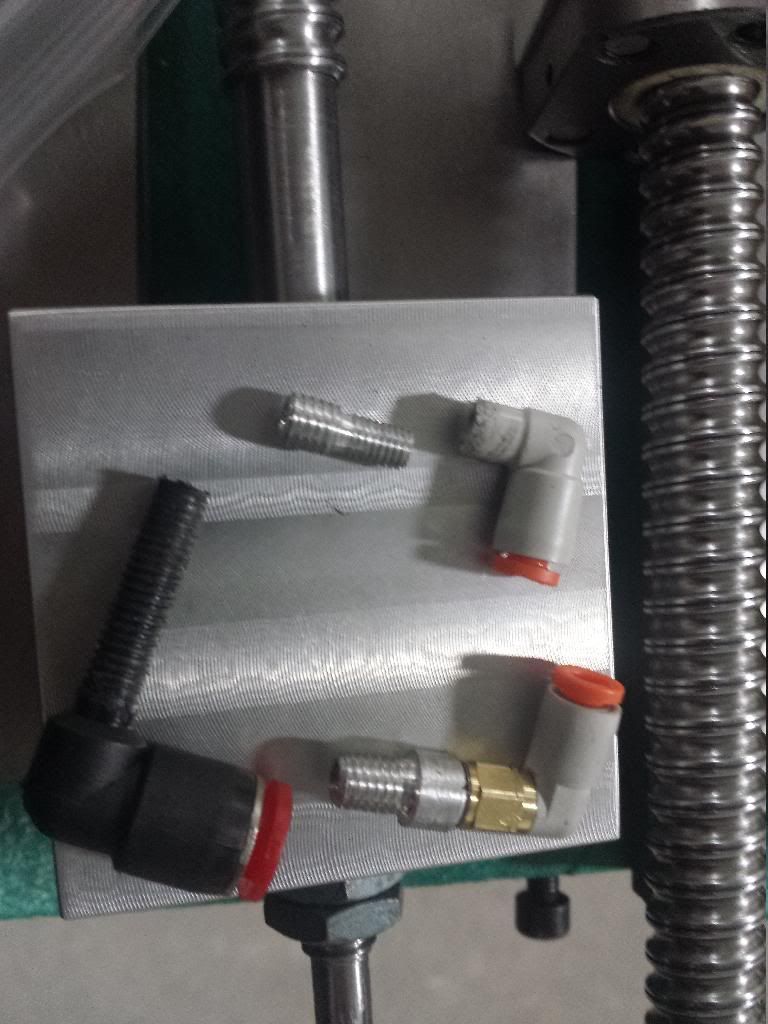
On the saddle I used 1/16 NPT fittings Link Link
For the Z I used some fitting from Arc Euro Trade
If I were to do it again, I would try to use fittings from Arc Euro Trade for the X and Y ball nuts.
Hope it helps,
Andrew
-
10-21-2014, 10:24 PM #160
Gold Member
- Join Date
- Aug 2010
- Posts
- 630
Re: Andrew's G07040 build
Looking at what they have..
Looks like they have a 90degree elbow going to M6x1.0 male to M8x1.0 Female.. The M6x1 part will work.. but.. I wonder if the elbow would fit. Trying to come up with a bill of goods for my setup. I've not done any machining yet. Will work for the Z-Ball screw cause that's what your using. I don't see any T's Just junction bars.. Which I guess a 3 Way bar IS a T.. Hmm..
Looking at 20140714_113729_zpsqohfqnoq.jpg Photo by wiggles84 | Photobucket Were do you go into the saddle on the NEAR side.. I see where you go into it on the far side. Looks like you eliminated T's and went with all direct connections to the manifold. I'll have to think about this...Inner Vision Development Corp. - http://www.ivdc.com
Website Design & Development. Shopping Carts, SEO and more!

 Reply With Quote


Similar Threads
-
Andrew's G0704 CNC Conversion
By andrew2085 in forum Benchtop MachinesReplies: 12Last Post: 01-21-2013, 06:04 PM -
Mint's Build Aluminum/Steel Build thread.
By FreshMint in forum Maintenance DIY DiscussionReplies: 0Last Post: 10-31-2011, 04:18 AM -
Newbie - To build or not to build Router/Plasma Table
By dfranks in forum Waterjet General TopicsReplies: 10Last Post: 04-08-2011, 05:16 AM
