


It's been some time since I posted anything on these forums. Heck, it's been sometime since anybody has posted. Anyway, after reading Mechie's post, I figured I might as well jump in. Maybe revive these forums
I made a few changes to the mill and more are coming. One of the changes was the cooling system....it had to go. I was sick and tired of the tiny little drain getting clogged up and the pan filling with coolant. So I drilled a 4 inch drain hole on the opposite side of the original drain. I also upgraded the coolant pump and tank.
Here are some pics...
I re-purposed my grand kids toy boxRight now , it has 20 gallons in it. I think I can do 25
I don't have a picture of it, but after cutting the hole and removing the old drain setup. I epoxied in two pieces of 4" diameter, about 2" long tubing (one for each drain). Without this, the coolant would travel through molecular adhesion, beyond the tray area and you'll get coolant everywhere....Oh and thanks to the coolant issue, I also removed the power supply from under the mill and installed it in its own enclosure, mounted on the rear wall of the mill.
I also installed new plumbing for the coolant..using 1/2" pvc. Where the original setup came up from the drain area, it now comes in through the rear.
I also installed a wash down hose....
So much better than blasting chips with air.
I had some neoprene laying around and figured I put it to some good use....
So what's up for the near future... I mentioned it in mechie's post. I'll be installing these.....
They are... a 1200 oz.in and two 940 oz.in steppers. I been having some issues with the Z loosing steps and instead of chasing my tail looking for the reason, I'll just install all new steppers and digital drivers.
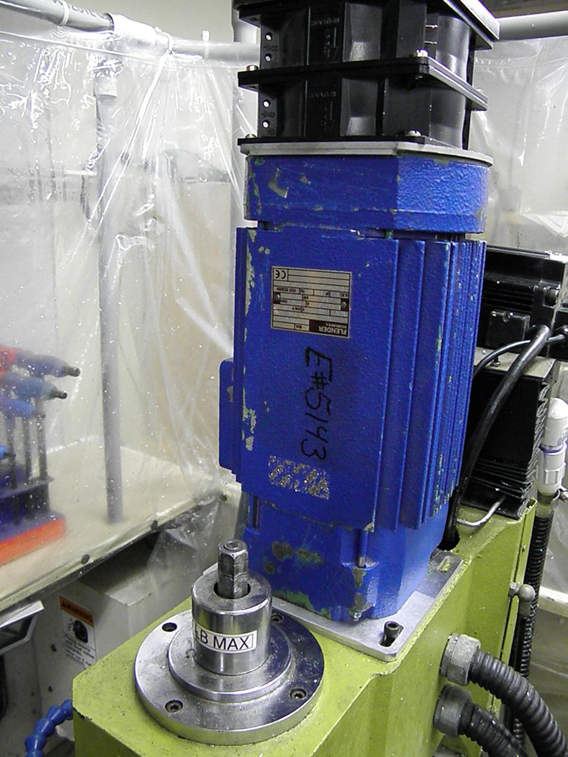
Lastly, I have some choices for the spindle motor. I have a 4 pole motor setup, very similar to Allen's setup. I also have a Kollmorgen 3KW servo, it has a resolver attached to it and I found a driver for it that may work. But, this servo stuff is kind of a new to me and I don't want to have the mill in limbo learning this stuff.......I also have this bad boy... A FLENDER HIMMEL 3KW (4hp) AC motor.
The beauty about this thing is that it has a 4 1/2" mounting base.. The frame is aluminum, but the front bracket is cast iron. Total weight is about 40 lbs.
When i got it home, I took it apart to make sure things were ok and found that the fan was missing. I was kinda of upset, but, I figured I can come up with a solution and here it is....
I had a couple 220 volt case fans taking up space and put them to use..... I gutted out one fan to act as a spacer to clear the shaft.
I hooked the motor up to a vfd and gave it a test run. It ran great at 4000 rpm, so i took it to 6000 rpm, then to 8000 rpm, I went to 10,000 rpm and it purred like a kitten. I chickened out going further, but, it sounded like it could take more.
I'm really leaning towards this motor as all my machining is with aluminum. I've also been looking at maybe a second mill and it won't be a Mikini .....
That's it for the updates... and sorry for the long post ...was kinda bored and hopefully we can revive these forums
Thread: More Mikini Modifications
Results 1 to 20 of 50
-
05-14-2013, 03:23 AM #1
 Registered
- Join Date
- Jul 2006
- Posts
- 367
More Mikini Modifications
pete
-
05-14-2013, 02:24 PM #2
Gold Member
- Join Date
- Feb 2009
- Posts
- 2143
I totally fried my coolant pump last week. I hadn't used coolant in forever, so it had all evaporated. The V25 version of BobCAD defaults to "coolant on". I was cutting wood, and didn't need coolant. After 15 minutes of running it started to smell, but I thought it was due to the treated wood I was using. A bit later I saw a waft of smoke, and reacted - finding some flame down in the coolant "pit"! Needless to say, I am pretty sure the pump is toast... Glad to see your Harbor Freight option, will be getting one of those. I also lost all the accessories (coolant pump, lights, oiler), so I suspect it did finally pop a fuse/circuit breaker. I haven't looked in to where to reset that yet as I had to hit the road on a business trip...
I'll post some pix and video of what I made in a few days...CAD, CAM, Scanning, Modelling, Machining and more. http://www.mcpii.com/3dservices.html
-
05-14-2013, 05:54 PM #3
Registered
- Join Date
- Sep 2009
- Posts
- 45
"They are... a 1200 oz.in and two 940 oz.in steppers. I been having some issues with the Z loosing steps and instead of chasing my tail looking for the reason, I'll just install all new steppers and digital drivers."
Slowtwitch, make sure your stepper motor will fit in the z-axis location; it can't be any longer than the current stepper motor unless you plan on putting spacers under the z-axis column. If you want to reduce the load on the z-axis, you could replace those gas springs on the column with pneumatic cylinders (link toMcMaster-Carr )and increase the air pressure in them until the current running the z-axis stepper (measured with a current clamp) is the same when the z-axis goes up as when it goes down. I assume the z-axis is loosing steps when it is going up, but there could be a lot of force going down if you are drilling / plunging. I've considered using the air cylinders and a dedicated air reservoir myself to reduce the wear on the z-axis, since the current air springs don't provide a constant lifting force. There are also magnetic springs, but they are buko bucks link:LinMot - Products - Magnetic Spring
-
05-14-2013, 06:28 PM #4
Registered
- Join Date
- Jul 2006
- Posts
- 367
Thanks for the info. I'm already looking into replacements gas springs. I figured I would need something different if I go with any one of the AC motors.
pete
-
05-17-2013, 12:04 PM #5
Registered
- Join Date
- Jul 2006
- Posts
- 367
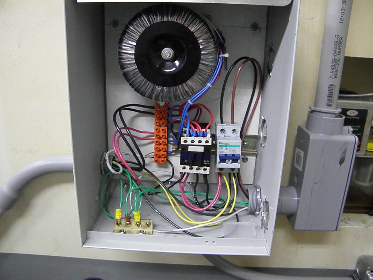
I mentioned in an earlier post that I moved the power supply from underneath the mill to the rear. Here are some pictures....
I re-purposed this control box that was being thrown out were I work
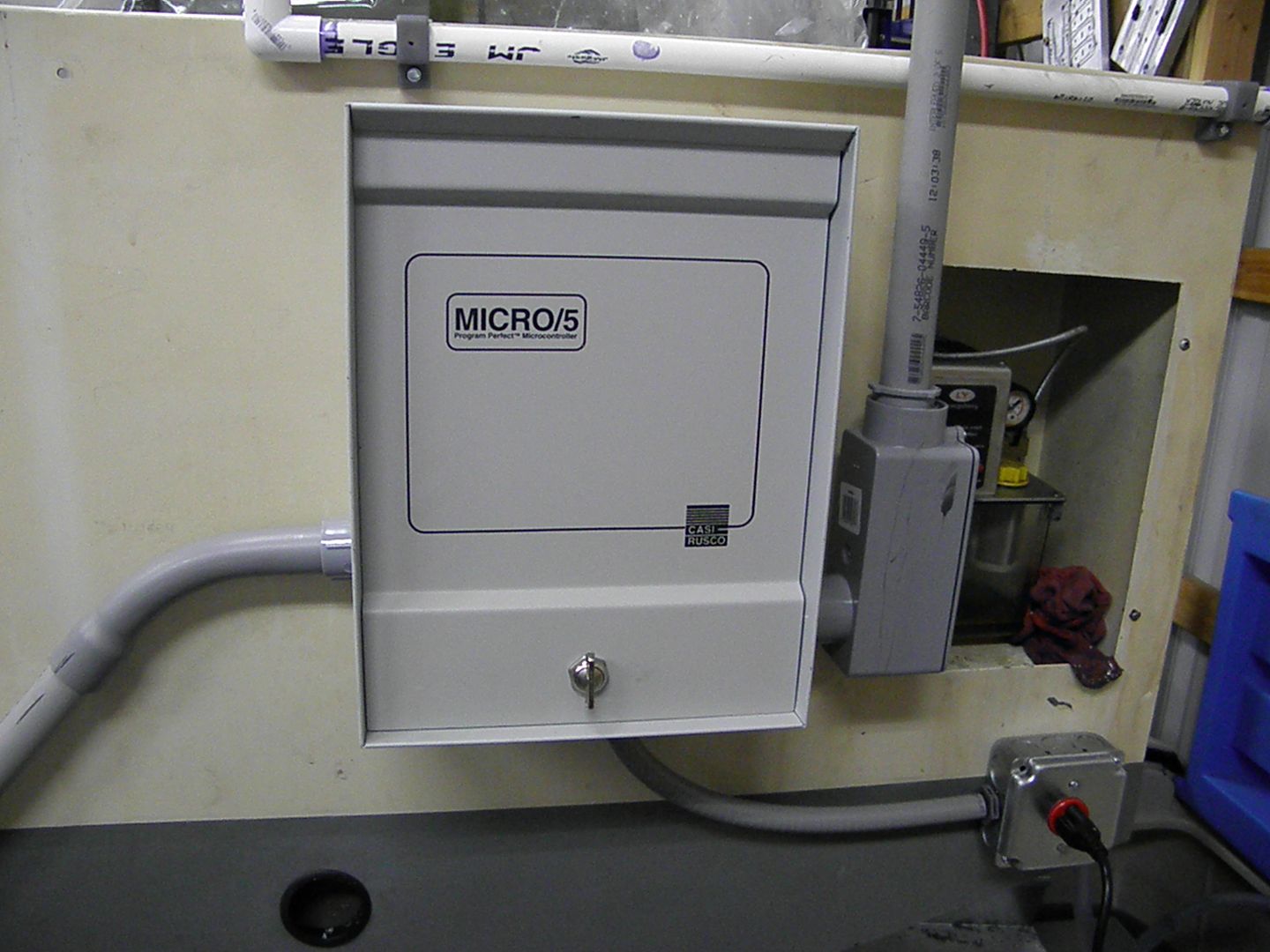
Made up a new mounting plate out of some scrap aluminum and bolted all the components to it.
I ran a temporary conduit to access the soon to be replaced electronics...
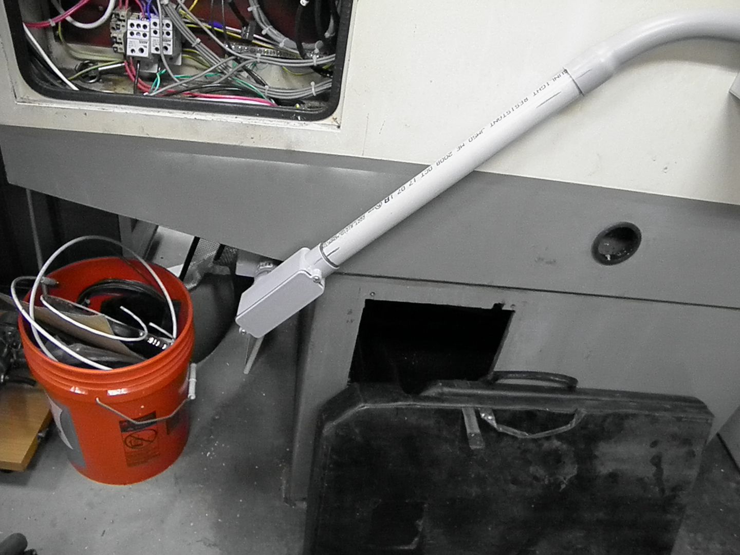
The new electronics will be installed in metal boxes mounted to the rear panel, next to the power supply. I'm just waiting for the company to replace the control boxes at work and scrap them
Lastly, I decided on a different breakout board. I initially was going to use a CNC4PC C23 board, but, have switched to a PMDX 126, with their 107 speed control. Will see how that all goes
pete
-
05-22-2013, 04:09 AM #6
Registered
- Join Date
- Feb 2011
- Posts
- 605
PMDX 126 +107 + Ethernet Smoothstepper is a nice setup.
PM-45 CNC conversion built/run/sold.
-
05-23-2013, 02:55 PM #7
Registered
- Join Date
- Aug 2010
- Posts
- 599
Hey Pete,
Good to see you back in the saddle. It was sad to see this forum die for so long but understandable. Great Mods and I hope to be able to use my machine soon as well. I'm currently setting up my garage to move it into so I can get it out of the house. I've been thinking of doing a youtube series ala John Grimsmo when I can get my life and family back together. I've been out of the CNC game for some time, first marginally so due to this ridiculously buggy and dodgy Mikini, then I had some major unexpected health issues that I'm still trying to work through, then found out my 1yo baby has cancer and have been virtually living in the hospital with him since December, only to return to work to be told I'm being laid off this fall from massive budget cuts at the NIH. So yeah life's hard sometimes. My gears are now shifting into providing an income source for my family through my currently stagnant business, and I will choke every ounce of life left out of this flaky machine to make that happen. Learning from your mods and the mods of others like Allen and Phil will help me do that.
I've been soundproofing, smellproofing, waterproofing, climate controlling, wiring, and lighting my garage to make the move sometime within the next month or so. Then my number one problem will be the *&%$&&^%)&%&^%$&% spindle. I'll tackle that when I get to it though. I just don't know enough about it to do the conversion yet or even what parts I will need or which direction will be the best way to go with that, but I'll have to make do for awhile until I can raise enough money. I light duty machining kickstarter project may be in my future we'll see. I would love to sell this thing and replace it with a Tormach or UMC 10 something but I have to make this Mikini turd work for now.
My next purchase will need to be the smallest quietest air compressor I can find that will be enough to run a small sandblasting cabinet. Something with no bigger than a 30gal. tank because my garage is tiny. I don't know much about compressors other than the 6 gal 3.4CFM@90 one I have absolutely sucks for anything but a brad nailer and is louder than a freight train.
-
05-23-2013, 04:29 PM #8
Registered
- Join Date
- Jul 2006
- Posts
- 367
Swath, It's great to see you posting again. I hope all goes well for you and your family. I think as a group we can overcome the issues with this mill. I too thought of selling, but, I just couldn't bring myself to pass this mill on to some unsuspecting soul. As Allen, Mechie and others have said, the mechanics of this mill are sound...it's just the friggen electronics that suck.
Hang in there... if I can help you... I will.
As for an air compressor...there are some really quiet ones out there (search ultra quiet air compressor). The only thing is that most are for nailers and such. If you can't find one of the silent types to suit your needs, look for an older reciprocating unit that requires oil. I had an old 2hp Kellogg with a 60 gallon tank, that was rather quiet...bought it on Craigslist for $80.
I'm getting very close in doing my conversion. I found a company in England ( Beltingonline.com, Supplier of power transmission and conveying products ). I had a hard time finding a pulley to fit the Mikini's belt size in the states. They made up a pulley for my new motor. It cost $72.00. They bored it for my shaft size...which is 30mm and cut in a keyway. I was going to make a new mounting base, but, it looks like I can reuse the old one.
All the components are on my workbench and I'm going to wire everything up and give it a test run...hopefully this weekend.pete
-
05-23-2013, 04:57 PM #9
Registered
- Join Date
- Sep 2009
- Posts
- 45
Hi Swath,
First off, sorry to hear about your son's condition. As for the Mikini, my wife is always chiding me about how I spend so much time on my mill, and so little comes out of it, hence the Flashcut / Electrocraft mods.
For the smells, you may consider getting an activated charcoal filter (see Mcmaster-Carr 4043T45). I put one near my dehumidifier's exhaust fan so it cleans the air almost continuously. Also, I found making a plastic enclosure like the one found somewhere on CNCzone or youtube really cuts down the odors. My 4th axis leaks hypoid gear oil...umm such a nice fragrance...and that odor is almost eliminated by the cover. I've found that 1/8" polycarbonate works well; it's relatively inexpensive, tough. easy to saw without cracking / chipping, and it bows a little in the middle, so coolant drips into the enclosure instead of pooling on the edges. I did have to reinforce it with some aluminum 'L' shaped bar though, because it sagged a little too much.
For the spindle mod, I'm trying to post what I hope others will find useful. I've had to do tons and tons of research on motors, motor controllers, steppers, wiring practices, et cetera, and I'm a mechanical engineer whose worked alongside electrical engineers. I can't imagine what the average Joe Mikini-owner would have to wade through to make this happen. Best of luck, and let me know if you have any mod-related questions.
-
05-23-2013, 06:30 PM #10
Registered
- Join Date
- Aug 2010
- Posts
- 599
Thanks guys,
My son took a major beating from surgery and chemo but thankfully he survived and is in remission now and is expected to be fine for the most part. He lost some hearing, bone marrow, his hair, most of his liver and his gallbladder, but is a smiley little baby again now. About 100 cases of this particularly rare and aggressive type of cancer a year in the US...jackpot.
After reading Phill's links about Flashcut I've become highly intrigued. Of course I can't justify the price right now, but it looks like a great option. It made me wonder if upgrading to servos at the same time would be a good idea if for nothing else than the positional feedback, I don't know. I guess right now I'm 90% concerned with the hinky spindle, and 10% concerned with the other electronics. Anyone thought of using a torquey servo for a spindle? I assume it would be really expensive. I'm at the point where I don't want to run this machine enough just to make money, I want to run it enough so I can replace it with something else and then use that one for the business. So maybe upgrading things on it has a diminishing return but I need it to run at some capacity right now to get to that point. All I want is for it to work as advertised for the time being.
The other thing that bothers me a little about the machine is the R8 spindle. I hate to invest in a whole bunch of R8 collet chucks when I would like to use a machine with an ATC in the future whether it be the TTC with a Tormach, or a BT30 with a UMC10. I know I can adapt it to use TTC but to me it's kind of pointless without even a power drawbar.
I checked out the really quiet compressors but they have way too little CFM to use for sandblasting. I've read you need at least 10CFM@90PSI for that. I would really like a 2 stage oil lubricated 30 gal for under $500 but it is not a critical tool at the moment.
The smell and sound of the machine won't be an issue after it's moved into the garage. It is currently IN my house in the basement, bad idea. I just didn't realize Vactra #1 way oil stunk so bad.
The guy at Lowes tells me they are having a sale on shop vacs this weekend so I think I might pick up one the little 5gal stainless steel Blue Hawk vacs and dedicate it to vacuuming chips out of the machine. I think that would be much easier than trying to scoop them out with turkey forks and keep aluminum and steel separated for the scrap yard. I actually bought a big magnet to get the steel chips out but it is messy and tedious too.
I've got to do something like your coolant drain setup Pete. It kinda sucks a little the way it comes. My pump still works though so I may just wait until it breaks too, which judging by the sound of won't be long.
-
05-23-2013, 08:47 PM #11
Registered
- Join Date
- Jul 2006
- Posts
- 367
 Originally Posted by SWATH

I thought about using this Kollmorgen.....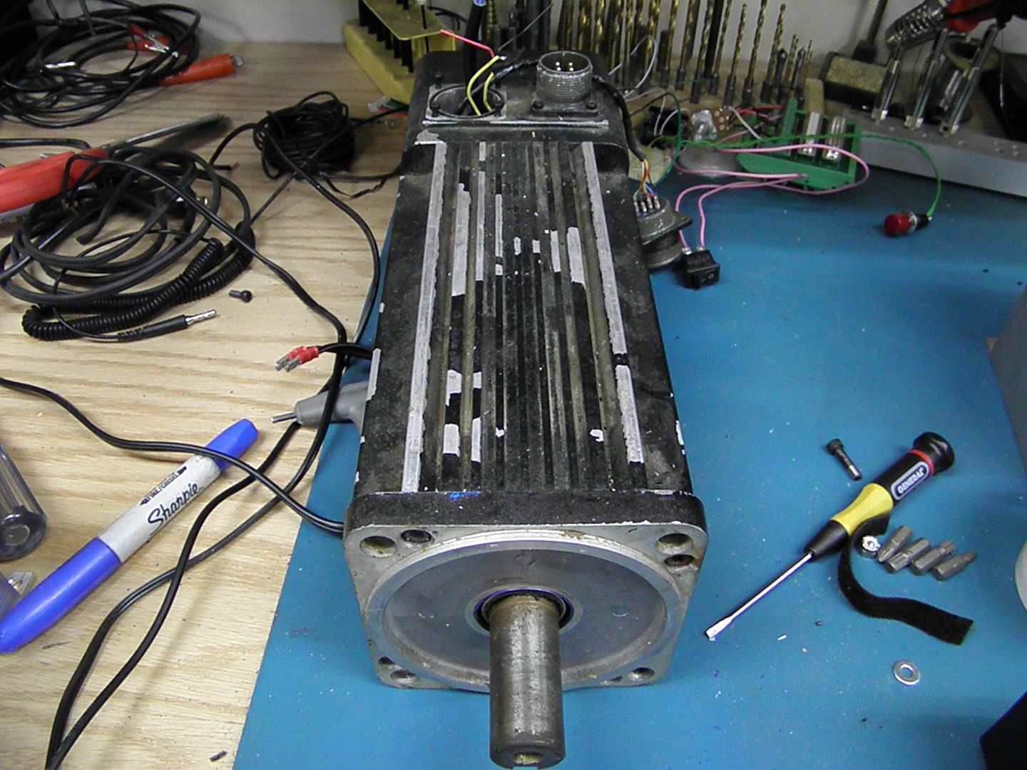
It's rated at 3KW and 6000 rpm...has a resolver for feedback. I am still learning about servos, so it's sitting on the bench till i can figure things out. There seems to be limited info out there about these things and folks that do know about them are very cryptic in their answers.
I may have mentioned it in another post that I'm also going to see about deciphering the pinout on the servo controller and bypass Mikini's BoB and use a CNC4PC board or the PMDX, to see if it would make any difference with the spindle. I keep thinking about the quality of the PWM signal and such that is produced with the Mikini board. Also, I want the capability to override the limit switches from Mach when a limit switch is activated. Currently, when a limit switch is activated, I shutdown the machine, move the stepper/ball screw by hand and turn the machine back on.... thanks to my non working front panel.
One thing I will do this weekend...is trial fit the 3kw A.C. motor. I installed the pulley and I want to check the fit. I may hot wire the motor to the VFD and see how the Mikini likes 10,000 rpm pete
pete
-
05-23-2013, 09:36 PM #12
Registered
- Join Date
- Aug 2010
- Posts
- 599
I would love to see the honker on there. Since it is 3KW would you have to upgrade the amp rating of anything to handle it? Wouldn't that be jumping from ~10A to ~13A? I don't know what the Mikini electronics are rated for in reality but Phil told me something like the 20A circuitry is actually rated for up to 30A.
I would just love to see some kind of motor work correctly without too much hassle especially an AC servo.
-
05-24-2013, 02:25 AM #13
Registered
- Join Date
- Jul 2006
- Posts
- 367
I mentioned that I installed a second drain hole....here it is...
I centered it with the webbing in the castings that are underneath the base. I didn't have a hole saw that would cut the casting, so I did it the old fashion way....a bunch of holes close together and then filing it smooth. It really relieved the back log of coolant that i use to get. Especially when the narrow portion of the front and back of the tray would clog up. I am really pleased with the way the coolant mods have worked.
Now for the fun stuff.. I removed the Mikini servo to see how things would fit with the AC motor. I thought I could reuse the original flat metal bracket, but, the center hole was to big. so I decided to make a new bracket....Here it is with my new pulley...Btw, these are HTD5 36 tooth pulleys, 25mm wide. It's wider than the original, which is 20mm, but, I figured the front pulley will keep the belt in place. The belts are HTD 5m-450 20 mm wide.
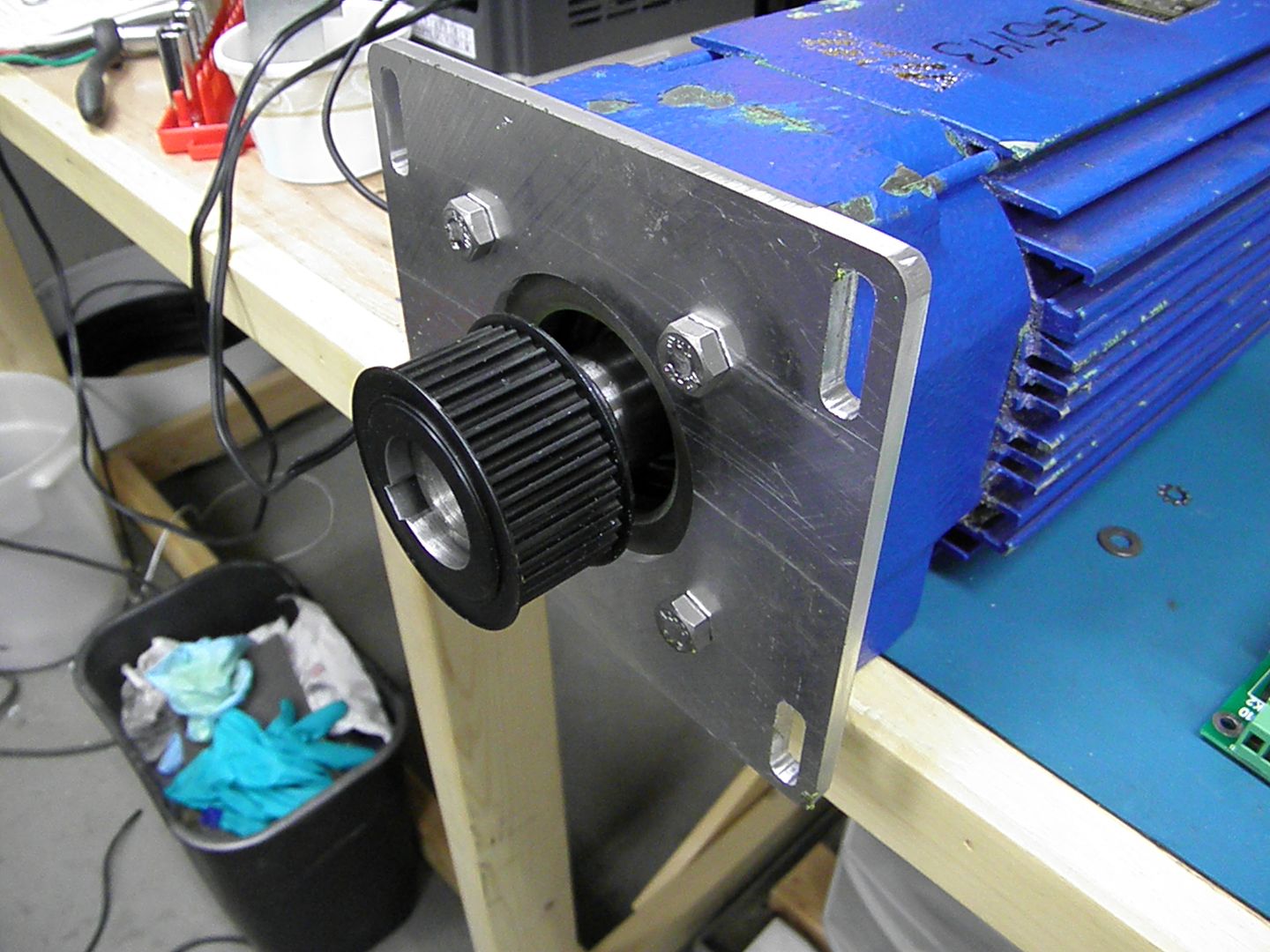
and here it is mounted.....The belt fit great.
another perspective...
I also turned on the mill to see how the Z would react to the new motors weight. I was pleasantly surprised that it responded like the original motor was still mounted. It moved nicely pressing just the up/down buttons. Pressing shift and up/down for full speed also sounded good. Over the weekend, I'll put it through some workouts using an indicator, to see if it's losing any steps.
As mentioned in my prior post, I'll install the motor and do a temporary hook it up to the VFD and see what happens. Maybe cut some aluminum.
pete
-
05-28-2013, 12:11 AM #14
Registered
- Join Date
- Jul 2006
- Posts
- 367
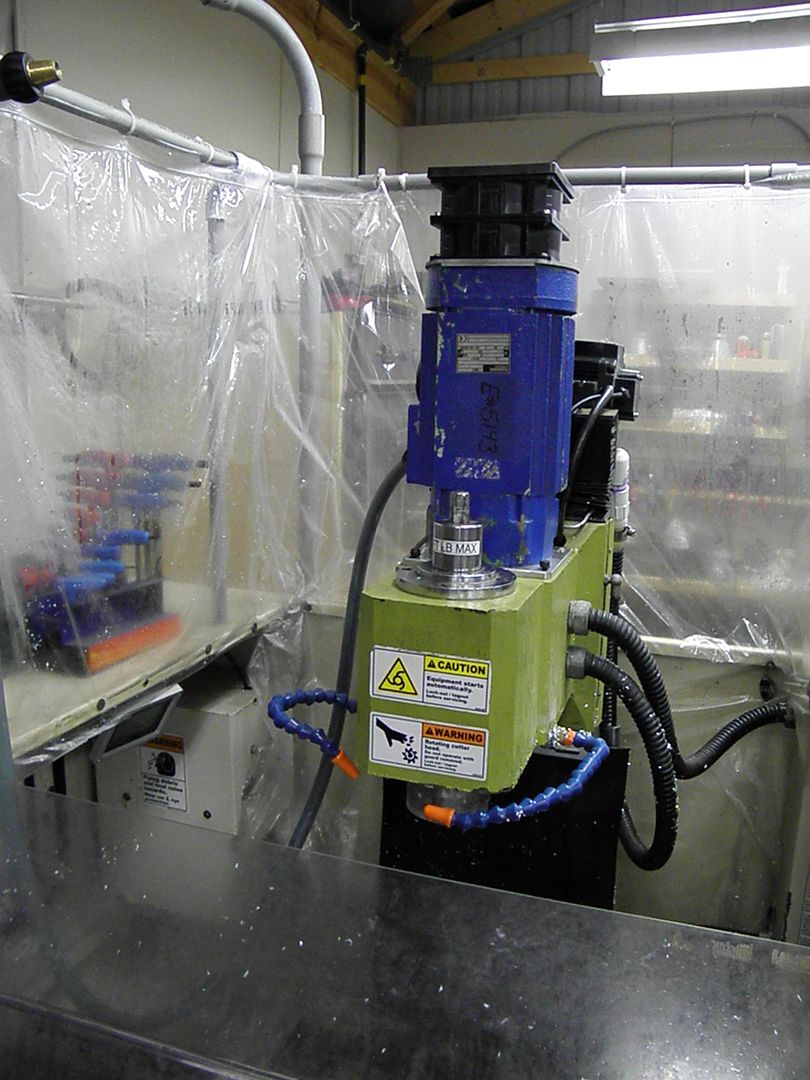
Well I had a chance to try out the AC motor on the mill. All I can say right now is WOW!!!!!! Why did i wait so long???????????? But, let's back up a bit......
I installed the motor and hooked it up to the VFD. It's the famous Huanyang unit that has been written about a thousand times on the forums. It's a 4kw unit. I bought it on Ebay for $150.00 shipped. I have one on my lathe and it's been running for close to two years. I initially had a problem with getting up to speed, but, it turned out to be a parameter issue. I forget which one it was right now, but, I had 60 typed in and changed it to 350 and all was good. Anyway, this is still a temporary setup, as I'm still running Mikini's BOB.
As I have mentioned in a prior post, the gas struts seem to be doing their job with the added weight of the motor. I'm installing all the electronics on the back of the machine...trying to eliminate as much of the cabling in the interior of the mill as I can. So I added a cable chain to keep things in order.
That's enough of the writing stuff, here's a video .......This is the mill cutting at 7600 rpm. I had it up to 10,000 rpm...but just cutting air
I'm still running a program made for the Mikini...hence the slow feed and dept of cut. I also turned down the coolant nozzles for filming purposes.
Some initial thoughts... I think Allen experienced it...the machine sounds so much more solid when cutting. Someone mentioned something about having mass and I have to agree with them. The code written in the video was a conventional cut, but, i was really happy with the finish after everything was cut. With the Mikini servo, you can see some marks on the angled sides of the parts. They just about disappeared with the new motor.
Next up, install the new drivers and the PMDX 126 with the Ethernet SmoothStepper. Then the steppers
more to come........pete
-
05-29-2013, 10:49 AM #15
Gold Member
- Join Date
- Feb 2009
- Posts
- 2143
Can you elaborate on the wiring needed for just this? I think I have one of those servo motors and a controller... "All" you need to do is wire up power and give it the PWM signal going to the current spindle motor driver? Can you link the post that describes that if it exists, or provide a little more detail here? Does it work in both manual and Mach modes, and for FWD and REV directions?
CAD, CAM, Scanning, Modelling, Machining and more. http://www.mcpii.com/3dservices.html
-
05-29-2013, 11:05 AM #16
Registered
- Join Date
- Jul 2006
- Posts
- 367
mcphill, The motor i'm using is not a servo. It's a 4hp ac 2 pole motor. I using a Huanyang VFD to run it. I'm also eliminating all remnants of Mikini's electronics. Thus, there will be no manual mode. Originally Posted by mcphill
Right now the motor is "cobbled in" wire wise...by that it's not connected to a breakout board. It's controlled directly from the VFD with a potentiometer. When i start the transformation to the new electronics, i'll try to have detailed wiring info
pete
-
05-29-2013, 11:20 AM #17
Gold Member
- Join Date
- Feb 2009
- Posts
- 2143
Ah, I see. Thanks!
CAD, CAM, Scanning, Modelling, Machining and more. http://www.mcpii.com/3dservices.html
-
06-01-2013, 08:21 PM #18
Registered
- Join Date
- Jul 2006
- Posts
- 367
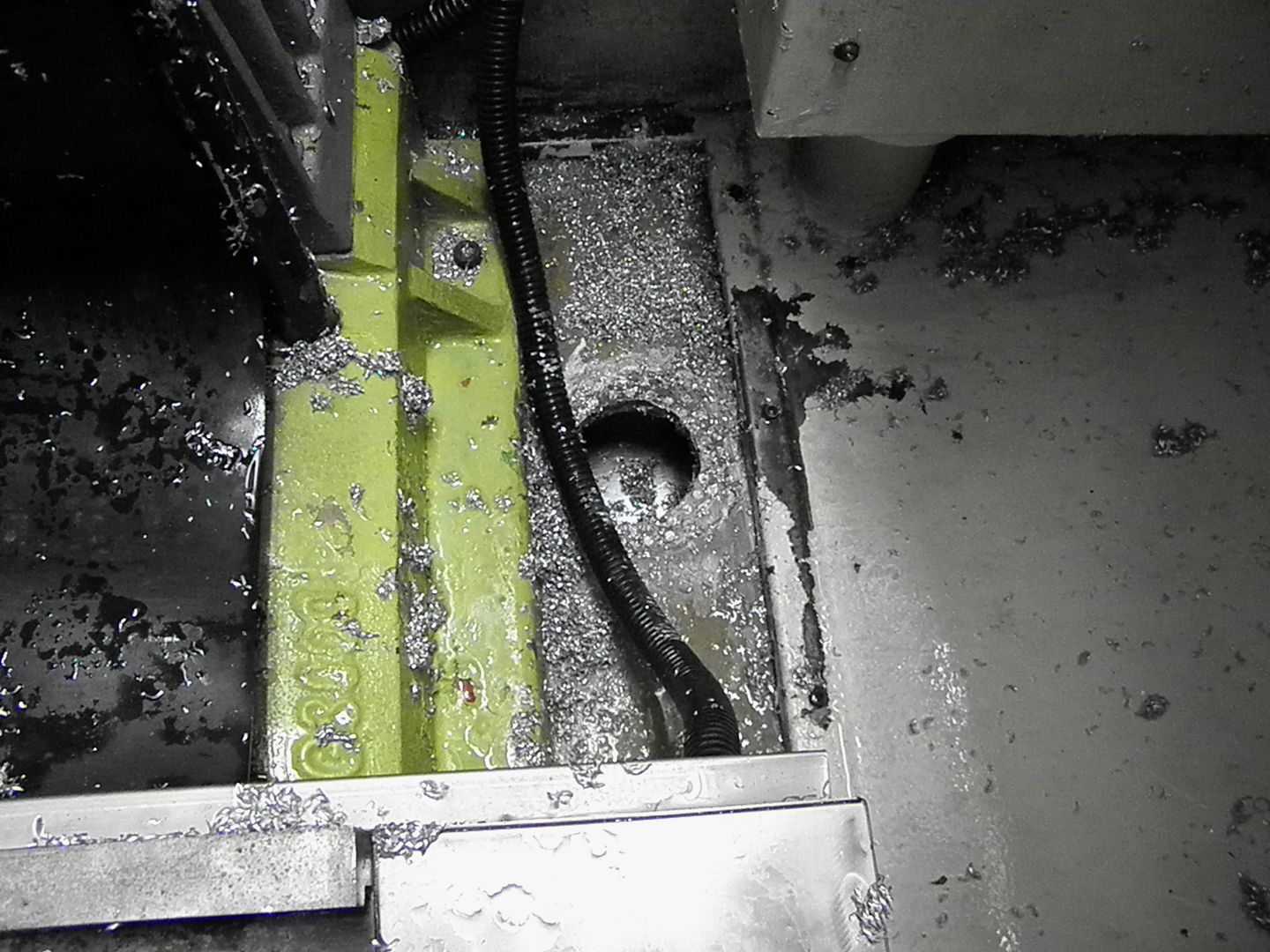
Hello folks, This morning, I removed the spindle column in my quest to replace the Z stepper. I was kinda of shocked at what I saw
 ,
,
This is what welcomed me...... This is where the Z stepper is located. It's amazing how the swarf finds it way.....
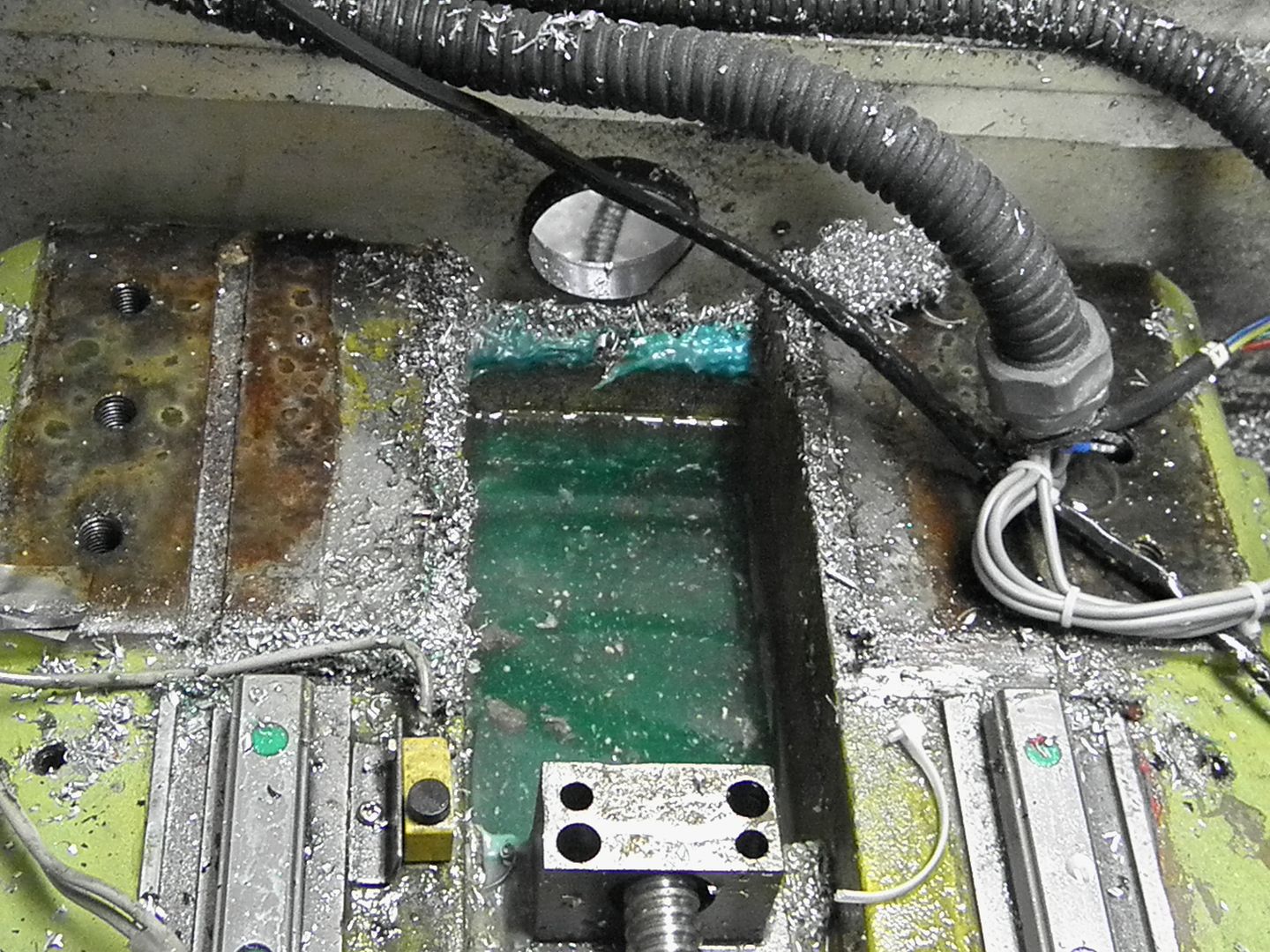
How deep is it......
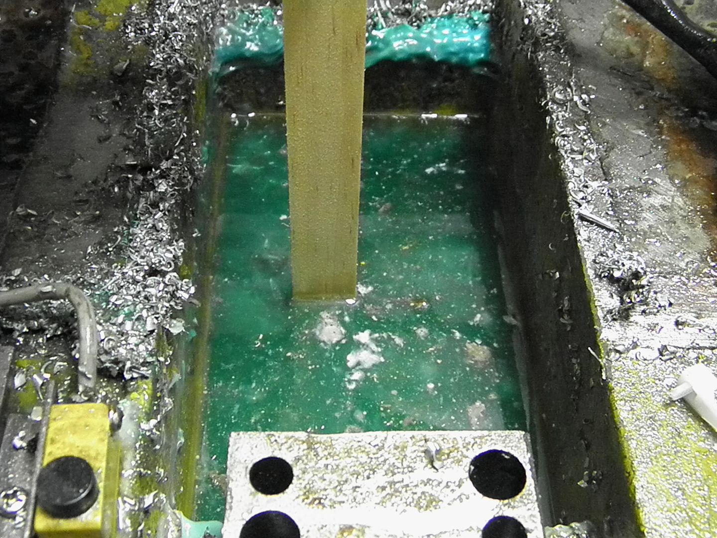
The stepper was immersed by about an inch....It's a wonder the bearings didn't fail or the motor's rotor rusting up or even shorting out.
There is a drain hole in the rear, but, it's only about 4 mm in diameter. It easily clogged up.
I was also surprised to see that the column was not pinned or keyed. I also didn't like the fact the conduit (for the wiring that goes in the rear of the column ) was not connected to anything...it just lays there with the wires going into to it
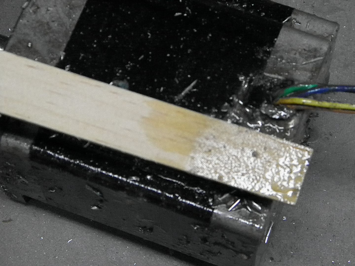
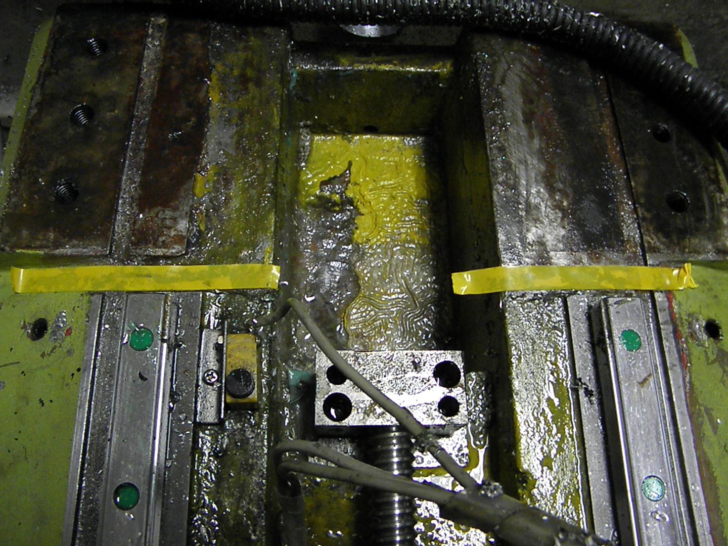
Anyway, as Mechi has stated, using the 1200 oz stepper will require spacers, as it's a tad longer. I'm machining a pair of 1 inch spacers. I took measurements and I don't see any issues with using my smallest tooling and collets reaching my work pieces. I'm also going to drill a nice size drain hole. That's what the tape is indicating...the location of my drain pan.
I plan to reroute all the wiring differently. Probably exiting at the top of the column.
I'm also going to test something different for limit and home switches. I have proximity switches, but, I seriously thinking of something like this....
http://www.youtube.com/playlistlist=PLme8A5tJEaiar3NSxiq8SknNxUCEWXpaa
They don't seem to be effected by swarf or coolant. We'll see
more to come....pete
-
06-01-2013, 09:58 PM #19
Registered
- Join Date
- Mar 2009
- Posts
- 199
I am actually in the process of pocketing out that area and building a cover with a drain for that same area.
-
06-02-2013, 12:04 AM #20
Registered
- Join Date
- Jul 2006
- Posts
- 367
I drilled a .750" hole in that pocket and epoxied in a piece of pvc tubing about 1.5" long. The pvc will prevent fluid from clinging to to the underside of the casting and dripping elsewhere. Btw, the casting is close to 1" thick in this area. Originally Posted by howecnc
Another thing I noticed when dismantling the column.....
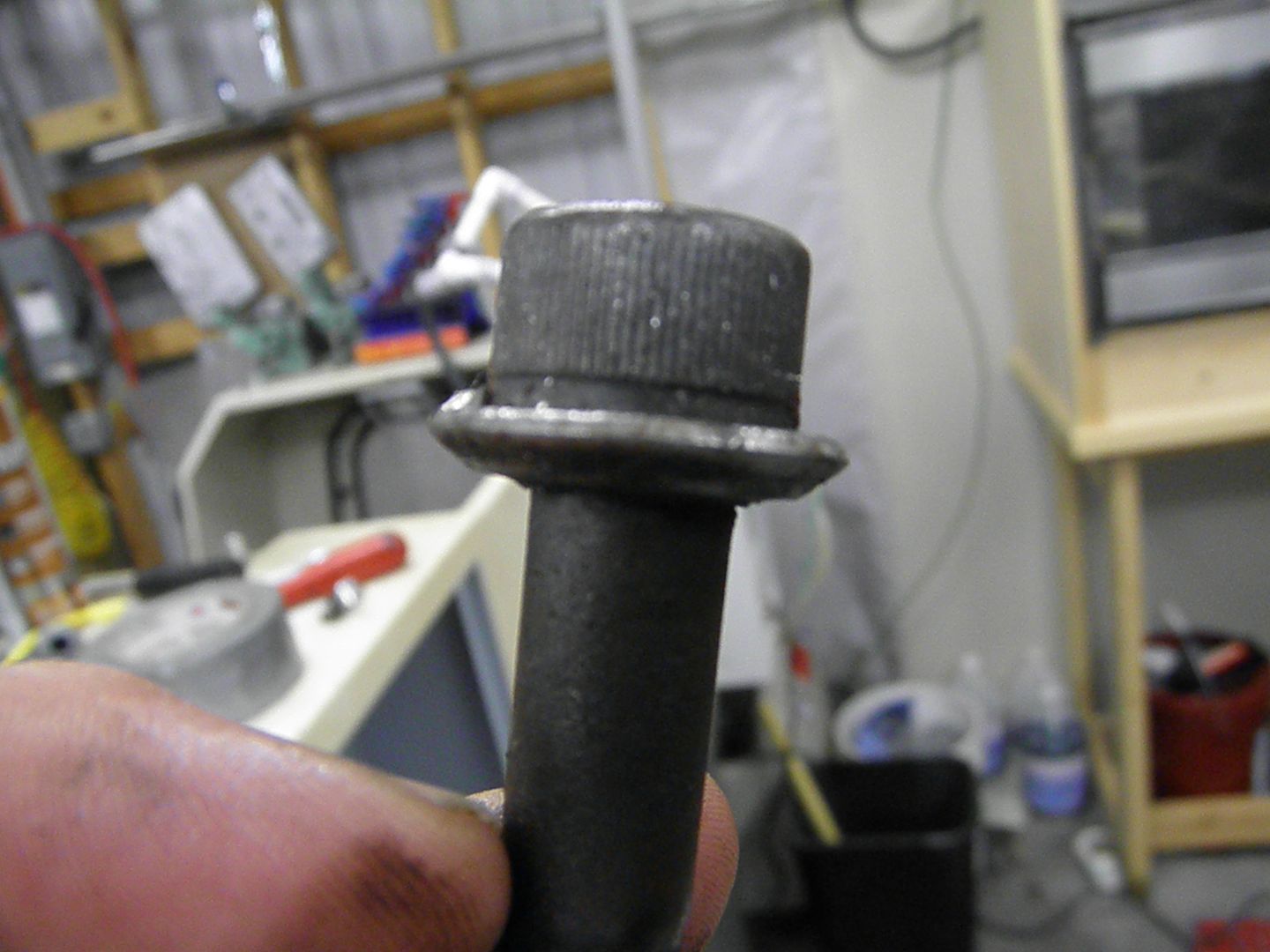
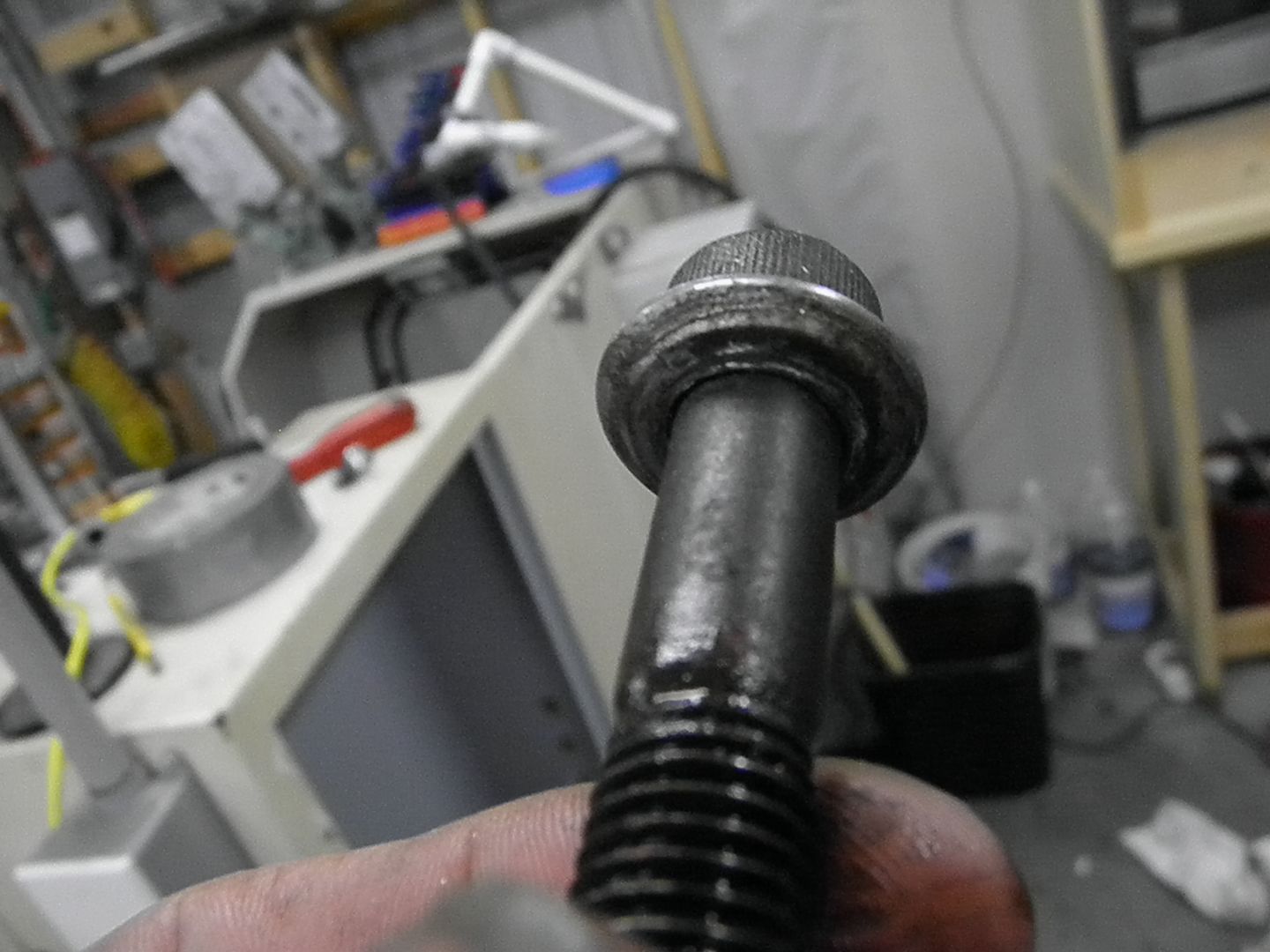
These are the bolts that hold the column to the base. As you can see the thin washers that were used where not doing their job. I wondered why my indicator detected movement when I pushed the column. I test fitted a hex bolt and there is clearance for a socket. I'll be ordering some grade 8 bolts to replace these.
more to come.....pete


 Reply With Quote


Similar Threads
-
SYIL X4 - Modifications
By mikie in forum Syil ProductsReplies: 23Last Post: 08-16-2011, 04:41 PM -
Modifications to my CNC Machine
By patchwork in forum Shopmaster/ShoptaskReplies: 3Last Post: 03-29-2011, 12:51 AM -
Cnc Modifications Links
By plasidboyy in forum DIY CNC Router Table MachinesReplies: 1Last Post: 01-08-2010, 06:29 AM -
Rockcliff Modifications
By alien_X in forum Uncategorised WoodWorking MachinesReplies: 5Last Post: 01-11-2009, 01:09 AM -
BOSS 8 modifications
By jonny in forum Bridgeport / Hardinge MillsReplies: 10Last Post: 02-17-2006, 06:13 PM
