


Hi everyone,
I'm designing a bearing support for a vertical shaft, but being more electronics / electric background I lack the mechanical knowledge, so I thought I'd ask on the most mechanical oriented forum on the web
The shaft is 25mm dia with two bearings, angular contact double row on the top - preloaded with a lock nut from the top, resting on a circlip - and a ball bearing 90mm lower as the 'floating' non-locating bearing. The fit for both bearings will be K5 or K6 (found different info from different sources), which is an interference fit. I was planning to mount a taperlock bush and puller in between the bearings (closer to the bottom ball bearing), but only just realised (duh) that due to the interference fit that might be rather tricky, especially as I was planning to keep the shaft at 25mm throughout to limit the amount of machining and it's effect on run-out. Assuming I keep the design as it is, with 25mm on the whole shaft, is it possible to use interference fit for the bearings and still fit the 25mm bore bush / pulley in between, after freezing the shaft and heating up the taperlock bush?
Regards,
Tom
Results 1 to 17 of 17
-
06-22-2013, 09:22 PM #1
 Registered
- Join Date
- May 2009
- Posts
- 16
fitting a pulley between bearings - same diameter along the shaft
-
06-23-2013, 03:06 PM #2
Registered
- Join Date
- Apr 2010
- Posts
- 294
I'm confused with your question - the bearings are a slight interference fit, but the taperlock bush shouldn't be, so why the need to heat it?
-
06-23-2013, 03:51 PM #3
Member
- Join Date
- Jan 2005
- Posts
- 15362
dsc
A drawing of what you want to do would explain things better, the top bearings, if they are preloaded together, should not be a interference fit, a just slide fit is what is needed, this is, you have the shaft around .0002 smaller max than the ID of the bearing, the pulley taper-lock should be a slide fit on the shaft, the bottom bearing, it depends on how you plan to fix the ID to the shaft as to what kind of fit it should beMactec54
-
06-23-2013, 04:25 PM #4
Registered
- Join Date
- May 2009
- Posts
- 16
Thanks for the replies, here's a what I'm trying to do:

the bottom bearing is suppose to be a floating bearing, but I didn't design it correctly as the outside ring should be allowed to move up / down, not the internal ring on the shaft (I was planning to have a slide fit on the internal ring, but I don't think that's correct). The top bearing is a double row angular, not sure what fit these need, I was under the impression that interference would be fine.
In between the bearings there's a taperlock bush and pulley, as I described above, I was planning to go with an interference fit on both bearings, so a slide fit bush would have to be heated in order to go down the shaft, past the interference sections for the bearings.
Regards,
dsc.
-
06-23-2013, 04:38 PM #5
Registered
- Join Date
- Apr 2010
- Posts
- 294
It may be you are over-analysing the situation. Unless this is some hyper-critical precision tolerance installation, with a precision-ground-finshed 25mm shaft and your bearings and taper-lock all for 25mm, you'll find the whole thing goes together just fine - the bearings should just be a gentle tap-on fit. You won't need an intererence fit on the upper bearing(s) as the circlip and top nut provide a positive location. The bottom bearing will probably float enough for normal expansion/contraction as drawn - and it would probably be easier to have it unsecured to the shaft rather than trying to allow the outer ring to move. If you were determined to have the outer ring floating then you could fix the bearing to the shaft with Loctite.
-
06-23-2013, 04:57 PM #6
Member
- Join Date
- Jan 2005
- Posts
- 15362
dsc
Your shaft in the front should be like this, a circlip is no good to do a preload up against, to preload the front AC bearings, they need to be able to move on the shaft, the bearing against the shoulder can be tight on the shaft, but the other one has to be able to move/slideMactec54
-
06-23-2013, 05:08 PM #7
Member
- Join Date
- Jan 2005
- Posts
- 15362
dsc
Is that a one piece AC bearing you have on the front, if so you can not preload them they are already set at the factory & are not adjustable, in this case it can be a interference fit, & the circlip would be ok, no need for a thread on the end, just a cap on the end of the shaft 6mm shcs to hold it in placeMactec54
-
06-23-2013, 06:02 PM #8
Registered
- Join Date
- May 2009
- Posts
- 16
Thanks again for the replies. It is indeed a single piece, double row angular contact bearing, I went with a thread and nut as I thought it would be a better idea than a cap and bolt (didn't want to 'crush' the bearing with the cap and bolt, with the nut I can simply secure it in place as it has a small grub screw on the side). Can I still use a slide fit with the top bearing? with the shaft being 25mm all over, it would make the taperlock bush go down easily without having to force it through the interference section for the top bearing.
The only other thing I'm not sure about is the bottom bearing and what fitting to use, interference or slide? I'd like this to be the non-locating / floating bearing. I think I have two solutions:
1. leave as is, with possibly slide fit?
2. change so that the outer ring can slide up/down and do interference fit on the shaft, with the bearing pushed against a circlip. In that case do I need another circlip or some other way to hold the bearing on the shaft? here's what it would look like:

and here's where the idea came from (SKF):
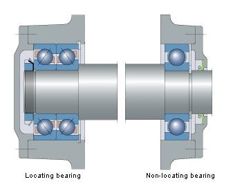
SKF shows the non-locating bearing pressed against a shoulder, secured with a circlip. In my case it would be pressed against a circlip, secured with nothing or a circlip? ease of assembly is something I'm looking at as well.
The idea is for this to be as precise as possible, with as little axial / radial play as possible. Shaft orientation is as per the drawing, vertical, there's a small load on the end of the shaft (downwards, not shown). Shaft will be in a steady temperature.
Regards,
dsc.
-
06-23-2013, 06:27 PM #9
Member
- Join Date
- Jan 2005
- Posts
- 15362
dsc
The thread is a waste in your case, a end cap will not crush the bearing in any way, the end cap would be pushing against the inner bearing race, which is one piece
so nothing you can crush
Yes all your bearings can be a slide fit, a little loctite would help if there is to much clearance, but you have not said what you want this for, it most likely can be designed different, than what you have it, which may be even simpler than what you haveMactec54
-
06-23-2013, 08:22 PM #10
Registered
- Join Date
- May 2009
- Posts
- 16
Thanks for the info, appreciate taking the time to reply. Here's a revised version:

Top double row angular contact bearing with a cap + bolt (not shown), resting on a circlip, bottom one pushed against a circlip with the outside ring floating. Shown a taperlock bush with a pulley in the middle. Still not sure how the bottom bearing is mounted, I'd like minimal runout, so I'd prefer a interference fit with a H6 fit on the outer ring. Still if that's too loose I'll get radial play which is not something I want.
The main reason why the bottom bearing is floating is that I'm not sure how precise the distance between the two mounting plates will be (to which the housings are attached). I know that a floating bearing is normally used when the shaft can expand due to temperature, but this is not going to happen here.
You've mentioned a simpler design Mactec54, care to expand on that?
Regards,
dsc.
-
06-23-2013, 08:40 PM #11
Member
- Join Date
- Jan 2005
- Posts
- 15362
dsc
The top looks good, the bottom as you have it would need to have a wavy washer under the out side edge of the bearing for expansion
You can't get much simpler than what you have at the top now, but the bottom, were & what is the shaft doing, How long is itMactec54
-
06-23-2013, 08:57 PM #12
Registered
- Join Date
- May 2009
- Posts
- 16
Cheers Mactec, appreciate the help.
I don't like the bottom as it is myself. The shaft extends around 100mm below the bottom bearing, the end will be subject to low forces (50N max maybe), both radial and axial whilst it's rotating at low speed (200-250RPM), but it needs to maintain it's position ie. axial play must be minimal. The shaft is belt driven and should not be affected by changes in temperature, so dimensions changes should be zero or close to zero. This is why I've used an AC bearing (mixed load) and a lower bearing for radial support and to stop any flexing. I've chosen a ball bearing, but maybe should've used a cylindrical roller bearing? just realised that will give me enough axial clearance when assembling, as this is really the only reason why I'm using a floating bearing in the first place.
Regards,
dsc.
-
06-23-2013, 10:14 PM #13
Member
- Join Date
- Jan 2005
- Posts
- 15362
dsc
In that case don't use the circlip on the bottom bearing, the shaft is all contained with the top bearing Etc
A roller bearing is always the best choice for a setup like this, the part with the roller bearing is to keep the grease in it, a seal in the bottom housing may be best for that, if you go with a roller bearingMactec54
-
06-23-2013, 10:49 PM #14
Registered
- Join Date
- May 2009
- Posts
- 16
To be honest I've used the circlip only as a point of reference, something to press the bearing against. If I decide on an interference fit, I will need some way of placing the bearing in the right point on the shaft. If it was a slide fit, I would simply slide the bearing on the shaft and bolt the housing into place and be done with it, but with an interference fit, the bearing won't move on the shaft easily, so it will have to be pushed into the right place. With nothing to push against, it will be a nightmare to get the right position.
As you say with a cylindrical roller bearing, grease retention will be something to think off. Also, I think the inside ring of a CRB should be an interference fit, so again I need a way to locate the ring on the shaft. Only other difference I think with the CRBs is that I can lock the outside ring down in the housing as the axial displacement is all contained in the bearing.
Here's an updated drawing, ball bearing vs CRB:

Regards,
dsc.
-
06-24-2013, 12:28 AM #15
Member
- Join Date
- Jan 2005
- Posts
- 15362
dcs
The roller bearing you have drawn is not the right type, either the inner or the outside needs to have a straight bore, in your case it is better to get the inner, which is straight, that way location on the shaft is not so criticalMactec54
-
06-24-2013, 12:46 AM #16
Registered
- Join Date
- May 2009
- Posts
- 16
Indeed it is the wrong type, I've just drawn it quickly to show that it's a CBR. To be honest I'd rather use a sealed bearing, which is why I'm leaning towards the ball bearing, it's also 1/4 of the price of the CBR. Here's a shaft shoulder approach, where the ball bearing is pressed against a shoulder and secured with a circlip, I've allowed for axial movement of the outer ring:

I can probably pull this off with circlips instead of the machined shoulder, although I'm not sure which is easier to machine, two circlip grooves or turning down the shaft from 30mm to 25mm. I'm also not sure what effect it would have on overall run-out of the shaft.
Regards,
dsc.
-
07-05-2013, 12:21 PM #17
Banned
- Join Date
- Jul 2013
- Posts
- 0
Barrel and Screw is an important part to establish a machine. Genca ensures a high quality and product increased durability of the screw and barrel that reduces your production cost. Visit us to find other services.


 Reply With Quote
Similar Threads
-
How to grind shaft of 2.0 mm diameter
By Ashish B in forum Uncategorised MetalWorking MachinesReplies: 32Last Post: 01-02-2011, 08:06 PM -
Fitting to Taper shaft
By Al_The_Man in forum MetalWork DiscussionReplies: 14Last Post: 03-27-2008, 06:18 AM -
X3 Motor Shaft Diameter
By pzzamakr1980 in forum Benchtop MachinesReplies: 3Last Post: 12-26-2007, 10:55 PM -
Shaft Diameter, LeadScrew Diameter, Motor Torque?
By cnc-newb in forum DIY CNC Router Table MachinesReplies: 8Last Post: 12-24-2007, 09:51 PM -
Shaft Diameter, LeadScrew Diameter, Motor Torque?
By cnc-newb in forum Uncategorised MetalWorking MachinesReplies: 0Last Post: 12-15-2007, 04:25 AM
