


OK, one more question for the pile (I'm starting separate threads for each to make them more "findable" by other chumps like me in the future)
I do a lot of parts that involve cutting a 2D profile all the way around the part. Right now, I'm either making soft jaws or drilling holes through the part so it can be screwed down to a fixture. Both add a lot of overhead for making one or two parts. I'd like to try making more use of holding tabs. What is the best way to accomplish this in BCC? (I have V25)
Results 1 to 10 of 10
-
07-31-2013, 08:48 PM #1
 Registered
- Join Date
- May 2007
- Posts
- 1026
Creating holding tabs for profile cutting
-
07-31-2013, 08:54 PM #2
Ghost
- Join Date
- Dec 2008
- Posts
- 4548
Nesting does tabs, or, you need to create your breaks for the tabs, and a profile op will jump there....
-
07-31-2013, 09:00 PM #3
Registered
- Join Date
- May 2007
- Posts
- 1026
I don't have the nesting option, unless it's included in the base package. Can you explain what you mean by creating breaks so a profile op will jump? I understand the basic principle but don't have the slightest idea how to do that in BCC. Originally Posted by BurrMan

-
07-31-2013, 09:05 PM #4
Ghost
- Join Date
- Dec 2008
- Posts
- 4548
Trim the section you would call a tab out of the geometry. The profile op will jump the gap to the retract plane.
-
07-31-2013, 10:05 PM #5
Member
- Join Date
- Sep 2012
- Posts
- 1195
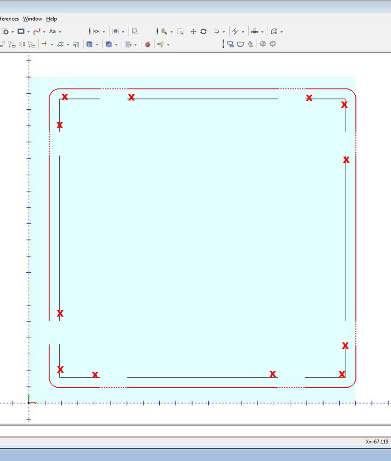
There is a bit of a caveat to doing tabs this way. You will probably not be able to use select all or a selection box to run a tool path like this. If you do, you'll find that the profile will jump to opposite sides of the lines and you won't be able to control which side it's on by using the left/right option. What you need to do, is select each line at the same end in a clockwise or counter-clockwise manner. If I'm profiling the outside of a part, I click in a counter clockwise pattern as shown in the image below. If I'm profiling the inside of an object, I do it in a clockwise manner. I also choose "left" typically for the offset side setting. You'll see in the image that the tool will rapid over the part between lines, essentially leaving the tab. If you are cutting a lot of parts and need the tabs to be thin (I often onionskin the tabs so the part breaks out easy), you can find the rapids in the program and hand-edit the G00 into a G01 move at a lower Z-value. That way, instead of pulling the bit out of the part entirely, it can be lifted only 1mm and by editing it to G01 it will continue at the previous feedrate. It's a bit more work than just doing a full onion skin at perhaps .5mm, so kind of your choice if you want to cut through most of the part with a little extra effort or maybe it's just easier to skin the entire bottom.
The "X" in the image below shows where I click on the lines as I go around the part edge in order to be certain that the tool path stays on the correct side of all of the lines. The red line is the toolpath, just easier to see that way than it is when it's green.
-
07-31-2013, 11:24 PM #6
Member
- Join Date
- Mar 2012
- Posts
- 1570
This video shows how the nesting software in V24 handles tabs. I agree that we should offer a tab feature for our standard profile feature and in the future I am sure we'll at this... Until then you need to change your part layout like described above or add the nesting option to your software.
Al DePoalo
Partner Product Manager BobCAD CAM, Inc. 866-408-3226 X147
-
08-01-2013, 03:32 AM #7
Registered
- Join Date
- Jul 2013
- Posts
- 32
I do tabs all the time with wood or solid surface material. First I profile the outside geometry down to a partial depth, for instance on 3/4" thick wood, I will do a full profile to a depth of 1/2". Next, I create a tabed profile. I make another layer with the same geometry but then draw 3/8" or 1/2" squares where I want the tabs. I then do a quick trim to remove the line segment representing the tab along with the square geometry remnants. I then create another profile cut on this tab geometry to full depth in one pass. This will leave tabs of just less than 3/8 or 1/2" wide and 1/4" thickness.
mmoe is correct that you will likely have problems with the direction of the profile selecting separate line segments representing the profile minus the tab line segments. I've solved this by selecting one line segment, compute toolpath, then Reselect and add the next segement and Compute toolpath after every selection to make sure the cut is on the proper side. It is a bit tedious to effectively select one line segment at a time but it works. You want to Reselect geometry that is adjacent to already selected geometry. Occasionally I had to add yet another tool path to select a set of geometries. Worse case would be creating a tool path for each line segement but I haven't had to do that.
Here are the two example geometry examples, one is full profile and the other is the tabbed profile.
Attachment 194214Attachment 194216
-
08-01-2013, 04:02 AM #8
Gold Member
- Join Date
- Apr 2009
- Posts
- 3376
Contours are usefull
-
08-01-2013, 08:53 AM #9
Member
- Join Date
- Sep 2012
- Posts
- 1195
If you select each line segment as I marked with a red X in my example image and do it sequentially in a clockwise or counter clockwise manner (counter clockwise in teh example), it will always come out correctly and is 100% predictable. You won't have to recompute the toolpath at all and should save some time since it is a lot less tedious than verifying each line segment individually. If you happen to end up with it on the wrong side of the line, it will be that way for all the line segments and you can fix it by choosing the opposite compensation in the profile operation settings. The key seems to be that you must select in a way that is clearly favoring one end of the line, and all the following selections need to favor the same end of the line as you work around the part. Originally Posted by rfenn
I do like your idea of doing basically an onion skin profile first (or last), combined with doing a tabbed version of the same profile. While it would take a bit more time to cut, it would be a lot easier to program than hand editing code as I've been doing it. I'm sure I'll be doing it that way from now on, thanks for the tip!
You should experiment with a thinner tab though. I've had excellent luck in most materials with a tab in the .5-1mm thick range, or around 1/32 inch. It's amazing what that little bit of material will do for holding a part still. Then you can easily cut it with a utility knife, if you even need a knife at all.
-
08-02-2013, 12:56 PM #10
Registered
- Join Date
- Jul 2013
- Posts
- 32
For simple geometries you can normally just select them in order and do more than one or all at a time but I have had issues doing the same thing with something more complex such as a moose profile. This will have a reverse in the line/curve segment direction which causes issues. Once I successfully build the toolpath for one object, I can generally manually nest these on a sheet and reselect the additional items one at a time and toolpath successfully. I don't recall if I was able to select multiple objects (only had 8 of them) and keep the profile cut outside.

 Reply With Quote
Similar Threads
-
Creating tabs in Mastercam x6
By Stevetotheo in forum MastercamReplies: 10Last Post: 09-17-2013, 03:40 PM -
Holding tabs?
By LessPaul in forum Dolphin CAD/CAMReplies: 5Last Post: 03-29-2010, 11:50 PM -
Holding Tabs
By webgeek in forum EdgeCamReplies: 0Last Post: 01-26-2010, 08:22 PM -
holding tabs in X3
By Sparky_NY in forum MastercamReplies: 4Last Post: 03-10-2009, 12:10 AM -
G-Code for holding tabs
By mikemill in forum Uncategorised CAM DiscussionReplies: 6Last Post: 06-05-2007, 12:38 PM
