


Hi all,
Ok finally taking the plunge and getting into doing toolpaths on solid models. (Therefore expect a lot of stupid questions) I've attached a part i'm working on. I got BobCAD to do what I want except for one problem. You'll see when running simulation on the toolpaths, ball endmill always leaves a radius on the edge of bore. Same when I cut a test part. I created a 2D boundary just above the bore on Z0, but mill still goes past it and puts a radius on the corner. Am I missing something or doing it wrong? How to keep a sharp corner on bore so that I can add the 45 degree chamfer after cutting the bore?
Thanks much
Thread: 3D Toolpath Boundary
Results 1 to 20 of 39
-
08-22-2013, 11:38 PM #1
 Registered
- Join Date
- Jan 2011
- Posts
- 380
3D Toolpath Boundary
-
08-22-2013, 11:45 PM #2
Member
- Join Date
- Sep 2012
- Posts
- 1195
I find that for some operations, the boundary is used for the center of the bit, not the edge. Just offset the boundary half the cutter diameter toward the middle, then use that for the new boundary. I can't say for sure because I use V24 and can't open your file, but I'm mostly certain that you are just using one of those features that the boundary is relative to the center of the bit.
Edit: Another trick that I employ A LOT, is to set the "top of job" to just below the top surface surrounding the area you are machining. In this case, the boundary is then set by the fact that it can't cut past the part wall and it will work essentially like using a tool offset. A combination of "top of job" and a boundary are also useful in other situations, so you just have to get some experience using those features to know when a particular one or combo or the two are going to do the job. Top of job and bottom of job are very powerful features and you'll use them a lot in solids machining to compliment boundaries since they are essentially top and bottom boundaries.
Here's an example of using Flatlands with a boundary in the first feature, and then without a boundary but with top of job set 1mm below the top surface in the second Flatlands feature. You'll see that the first method would result in some paths at the top of the part that are not really what was desired, while the second method (top of job) limits the cut to exactly what was needed. In other cases, where they may be more than one flatland below the top of job spec, you'd then need to also use a boundary to keep the feature within just that one individual area.
https://files.secureserver.net/0sEYMUXbyOi4qA
-
08-23-2013, 12:13 AM #3
Gold Member
- Join Date
- Feb 2009
- Posts
- 2143
The Z height of the boundary "artwork" has NO effect on how deep the toolpath goes. Sounds like you "intend" the tool not to go "deeper" than the boundary - but you can not specify it that way. Set your depth in the tool parameters for that operation instead. Think of the boundary as an "infinitely high wall" rather than a line... As stated, though, I agree that "sometimes" the boundary affects the diameter of the tool, and sometimes the center of it - I have not looked in to which applies when... If it simulates "wrong" I edit the boundary to make it "right".
That said, does your model have a sharp corner on that edge? If so, it should not be "gouging" in to that corner. If you have the chamfer in the model, I suggest you edit it out and use the "full size" for cutting the part, and add the chamfer as a CAM operation only...CAD, CAM, Scanning, Modelling, Machining and more. http://www.mcpii.com/3dservices.html
-
08-23-2013, 02:09 AM #4
Gold Member
- Join Date
- Apr 2009
- Posts
- 3376
TONY,
If I am understanding right,let me clear up a few things.First off,it doesn't matter where in Z your drawn boundary is.In your file,extract edge,get the boundary,good to go at height it is.When you select Geometry,select the whole model.Use a top of job setting that is 1/2 the diameter of the ball EM you are using,and have that in the negative.For your file,that would be -.3125 for top of job.
This is Ass umming that you already have Hogged the bulk of the metal out with a prior feature (that is not in your file)other than Equal Distance.Equal Distance is used for semi-finish and/or finish strategy.
-
08-23-2013, 05:19 PM #5
Registered
- Join Date
- Jan 2011
- Posts
- 380
mmoe: Thanks, that did the trick. Seems a bit silly to me that the software is compensating for the tool diameter in the cut, but wants to use the center of tool for boundary? Well ok, it works so I will remember it.
mcphill: Ok, thank you I will remember about the Z boundary. I was actually not trying to control Z height, just the diameter. But yes, thought it would also stop the height
JR: Will experiment a bit with the things you said. All a little new to me. hehe.. I was using the equidistant cut for roughing because I'm cutting Delrin not metal and it worked great for how I wanted to rough it out.
THANKS EVERYONE!
-
08-23-2013, 05:26 PM #6
Gold Member
- Join Date
- Apr 2009
- Posts
- 3376
If you are using Equal Distance for roughing,Your Top of Job should be set to zero then.Otherwise it will not give expected results (crash).
-
08-23-2013, 05:35 PM #7
Registered
- Join Date
- Jan 2011
- Posts
- 380
Yep. Luckily that's how I had set it up
-
08-23-2013, 08:25 PM #8
Member
- Join Date
- Sep 2012
- Posts
- 1195
There are times when you will see why it makes sense. For example, if you're using a ball end mill and you have a cylindrical hole with a radius on the top edge, using the boundary where the outside of the radius meets the top surface would not produce enough cut if the ball end stopped where the outside tool diameter hits the boundary. By following through until the ball end mill centers on the boundary, you get a full cut of the top radius.
I would agree that there could be more intelligence applied to the boundary feature and that would be pretty cool, but I'm not sure that's in Bobcad's hands. The software uses an engine for generating tool paths which is licensed from others, so for all I know the boundary behaviour is part of what the module applies. To make it better, it would have to recognize the tool tip that is actually cutting the surface, which would be quite difficult when you get to some of the more complicated tapered radius bits. In actuality, machining to the center of the boundary is the most easy to adjust from for those cases where it needs to be different, at least IMHO. It's very predictable and easy to do the math in your head as to what offset might be needed. As you get to know the system better, you won't even have to think about it to get the results you want. It just becomes automatic that you know what to do in each instance, so it's really not even a productivity issue when you are fluent with the software.
I've got my share of thoughts about how I'd like things to work in Bobcad the same as everyone else, but this case is really more a familiarity issue and less of a software issue. It's not the sort of thing were you're having to do a work around to get the job done because something isn't working right, which is the sort of thing that really does drive a person nuts. In this case, there is a system that doesn't require working around bugs and it will eventually make sense for you.
-
08-23-2013, 08:46 PM #9
Ghost
- Join Date
- Dec 2008
- Posts
- 4548
Using the tool center option will cut the top rim correctly, but then you would need to offset the bottom of the surface, or make 2 toolpaths. One for the rim and one for the rest of the cup.
Seems like normal ball tooling results.
We just stop the top of job, like mentioned, so the tip of the tool doesnt go over to the boundry.
-
08-23-2013, 09:02 PM #10
Gold Member
- Join Date
- Apr 2009
- Posts
- 3376
Yes mmoe,you probably nailed it ,,,Familiarity.
All I know is BoB
As a result,that is how I think,most of the time.Of course I have my ideas too.
As far as the Boundary issue,no problems here,way it always has been since I have used BoB.
-
08-26-2013, 04:26 PM #11
Registered
- Join Date
- Jan 2011
- Posts
- 380
Another Boundary Question
Ok Guys, I was doing good and starting to understand all the hints you were giving me. Got most features done. Now I am on bottom of part and can't get a finish pass to do what I want. If you look at model I have the step roughed out. It's a curved cut, but does not have a square bottom. The step is tapered. I want to do finish passes back and forth on just the step with a .010" step over. I cannot get it to do what I am trying to do. I've watched the training videos, but didn't see what I wanted. I think it is another boundary issue and I am probably just not selecting/creating the right boundary. I'm using a .500" endmill with a .030" corner radius to maintain the radius shown in corner of part. Anyone want to take a peek for me? Thanks again
Edit: Ok, found part of the problem. The step is not just tapered, but also has a radius in it. Good grief, something that can't be machined?
-
08-26-2013, 05:36 PM #12
Gold Member
- Join Date
- Apr 2009
- Posts
- 3376
Tony,I glanced at your file.I really do not have time to try and tool path it.But a couple things are striking out at me.First off you cannot use a 1/2 tool with .03 radius to clean bottom.You will"Scallop" the surface if the software were to allow it.That means it would violate the surface and scrap part.Visualize what the bottom of your tool is going to do to the bottom surface.There is no way it can follow the surface.You would need a much ,much smaller tool.Then the problem will become how long the tool will have to be vs. the diameter of tool.Probably bad results.Maybe you can rotate part and machine differently ?I think I am thinking right.Hoprfully you get it figured,but I have to go to shop now.
-
08-26-2013, 05:40 PM #13
Registered
- Join Date
- Jan 2011
- Posts
- 380
Yep, thanks JR. Was just looking a rotating the part 90 deg and coming at it different. I missed the 24" radius that was on the taper. Just have to see how I can use something other than a .063" ball mill to machine the entire feature
HELP!!
-
08-26-2013, 06:46 PM #14
Member
- Join Date
- Sep 2012
- Posts
- 1195
I was able to get a toolpath off of it the way it is, but the bit would have to have a long enough cutting length to cut the entire vertical wall. If that endmill with the corner radius has a 1.5" cutting length and perhaps another half an inch of clearance, I think it would work out just fine.
There were two things that I think you should change. First, you will often get undesirable results when you only select a surface or two of the part because the unselected surfaces of the solid will not be taken into account during the toolpath generation. This can cause toolpaths that go beyond the selected surface and into the unselected surfaces. I pretty much always select the entire object when making the selection unless there is a very specific reason not to.
The other thing is that the boundary in this case needs to be a window from the top and it needs to use the arc line that is at the top of the radius on the bottom surface (where your toolpath will start basically). It also needs to use a line which I would draw connecting the two corners of the outside of the geometry, with lines connecting the arcs to the outer line at each end. Once you have the window, you need to translate it to the X+ direction by .250" to account for your tool diameter. (edit I used the top arcs, so that's why my window is located where it is. If you use the arcs I suggest at the top of the fillet/radius, the window will be lower, but that's just fine as well.
I can't post a file since I only have V25 in demo mode (I use V24 Mill Pro), but I've taken a screen capture of what you could consider a rough draft. I used the top arcs and found they don't work quite right, but were pretty close which is why I'd say use the lower arcs at the top of the radius/fillet instead, which I think will prevent the motions to the top edge that you see here. Otherwise, this is just a standard Slice Planar feature with a .005" stepover and the Arc Fit box checked, otherwise there wasn't anything extra done in the settings. Just select the entire part, create and use the appropriate boundary and you'll be set (again if your cutting edge is long enough). Same process would apply if you rotated the part and machined it the other way, but it would obviously take a lot longer because of the surface area in that direction. I would try not to get all the way to the vertical surface and then just run a profile or pencil feature on it to make a clean final pass.

-
08-26-2013, 07:35 PM #15
Gold Member
- Join Date
- Apr 2009
- Posts
- 3376
mmoe,Are you sure ? ? ?
One word comes to mind "Scallop"
Can you post the V24 file??
-
08-26-2013, 08:21 PM #16
Member
- Join Date
- Sep 2012
- Posts
- 1195
I can't open his original file in my V24 since it's in V25 format. The image above is exactly from his file, and I did it just the way I described. If I had a V24 file I'd be happy to share it. I also can't save anything useful out of V25 since it's 5 day trial period ended months ago. For the most part, it's now only useful to read files and play with them, but can't output anything readable on licensed products. If the OP would post the original geometry as an IGES or SAT file, I could do it.
When you say scallop, do you mean finish quality or problems with generating the code? While I can generate the code, the tool selection may or may not be ideal and is not really accounted for. That's more a matter or personal preference I think since nothing really cuts these shapes 100% perfect unless they are ground to match the profile. Since in this orientation the bit is cutting exclusively with the corner of the bit toward the vertical wall, I'd think a .030" radiused edge endmill would be OK, but would need a pretty fine stepover with that small of a radius (I set it at .005" rather than .010"). I only cut aluminum and plastics when doing operations like this though, so YMMV. In aluminum, with the spindle speed that I run at (usually around 8k-15k depending on bit and feedrate needed to maintain tolerances), I'd expect a smooth surface finish using that bit. If anything, I think that there would be more problems rotating the part and working with it that way because the concavity is not tapering down to allow for a radiused end mill, so in that case only a ball end mill could be used. I'm more of a fan of using a radiused edge endmills than a ball mill where possible since the surface speed of the cutting edge is more consistent from the outside of the radius to the inside of the radius. It would probably be my preference to cut it the way he showed it originally, provided I have enough cutting length to do a cleanup pass with a Pencil feature and can make that cleanup pass seamless to the Slice Planar feature, which I think might be a challenge unless the fillet radius matches the endmill radiused edge (if so it would blend beautifully). I'm also not entirely sure if the vertical wall is actually vertical or has a draft since using the top edge didn't really work well, but the draft would be so minimal that I'm assuming it's meant to be vertical.
That said, my focus is not on ultra high tolerance machining, but appearance grade and non-appearance grade rapid prototyping to minimum tolerances as my machine can only hold about +/-.002". It's meant for speed and multiple part manufacturing more so than precision. Our perception of what an acceptable finish is my be quite different, but I'm pretty sure I'd get a smooth to the touch finish as shown since the cutting edge should remain tangent to the surface at all times.
Edit, a quick drawing in 2d cad shows that a radius of .030" with a .005" stepover produces a peak to valley scallop of around .0001043", but would be slightly more due to the angle of the surface essentially expanding the step over by a thousandth or so. Even still, it would be less than .0002". I don't know exactly how much clearance there is for that middle section to see how the bit would fit there. I'd have to look into it later. That might be where you are expecting the scallop?
-
08-26-2013, 09:18 PM #17
Gold Member
- Join Date
- Apr 2009
- Posts
- 3376
""If anything, I think that there would be more problems rotating the part and working with it that way because the concavity is not tapering down to allow for a radiused end mill, so in that case only a ball end mill could be used.""
Same can be said for OP"s file,the way it is positioned.
"" I don't know exactly how much clearance there is for that middle section to see how the bit would fit there.""
Yup,as your EM is trying to cut the lowest part,,the trailing edge will be cutting what you just cut.BUT,the software will/should not allow that,,SO,you end up with a part that is not cut to what the surface of the model is dictating.
-
08-27-2013, 12:10 AM #18
Registered
- Join Date
- Jan 2011
- Posts
- 380
WOW! Thanks for all the info ALL of you. I appreciate the time it took you to reply. And I did read it all, and used a little from what everyone said. JR was right in that I can't used a flat bottom mill. In V25 it will not allow the tool to 'interfere' and create scallops. That's how I noticed the radius finally. But, using a .125 ball mill to rough, and semi-finish, and then a .063 mill to finish and blend the corner radius, I think it will work. Gonna take a long time to mill, but it's only one piece, (will make 2). Could only get Bobcad to mill the tapered radius if I cut in the Y direction. That will work. And this time the Z boundary did actually control the height of cut because its a taper, which means there's some Y and X movement along with it. I've attached the 'final' file, so you can take a look. If you find a more efficient way to do it im all ears. But like I said, only a 1 or 2 part order. Sorry if you can't see mmoe, but I can post it as a presentation file if you wanted to see the cuts. Or maybe your demo can look at it again.
THANKS again everyone! (GOD, can you tell i'm GREEEEN??)
-
08-27-2013, 02:12 AM #19
Member
- Join Date
- Sep 2012
- Posts
- 1195
Yes, I think it just went part way into that dip without issue (no gouges). If a person wanted to, I suppose you could use the radiused endmill followed up with a ball end to clean out that dip. I think that would probably be my approach, but would also usually depend on what bits I have handy.

-
08-27-2013, 02:46 AM #20
Member
- Join Date
- Sep 2012
- Posts
- 1195
I can have a look, I just can't send anything back really. I suppose it could send something back if you had another computer running the Demo version since demos can open both regular files and demo created files, but you couldn't make code from it or save it in any way to make it useful.
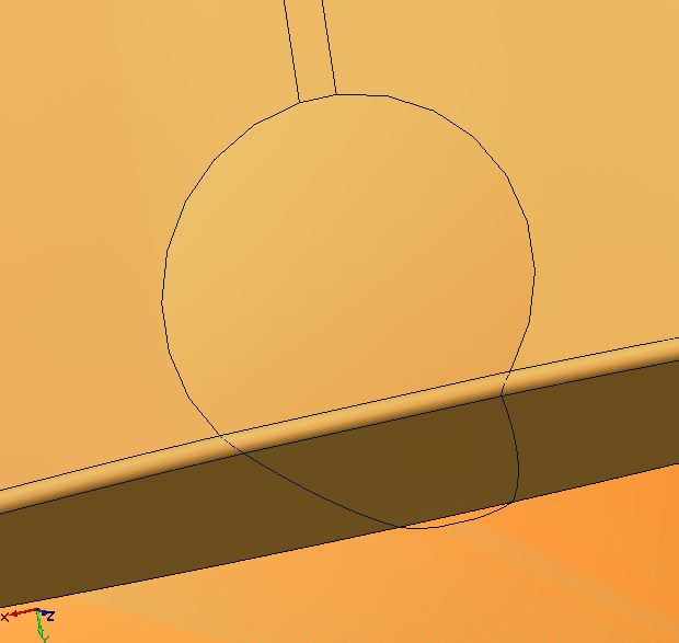
I opened the file and don't see any toolpaths, so not sure if you intended to include them or not. However, what I also see is that the geometry is how I thought. There is nowhere that the original tool should gouge in the original configuration. The area that looked (from a casual glance) like a cylinder subtracted from the tapered face is not actually subtracted, so there isn't anywhere that the tool would have to dip into. If you can post the file as a SAT (go to "save as" and select .sat), I can show you what I mean. Otherwise, to both jrmach and myself, it kinda looked like there was a dip in the taper which isn't actually there since I now see (on my desktop rather than laptop) that they are just surface lines as shown in the image below. There is enough taper to the face that the minor degree of concave-ness is not a factor for that radiused edge endmill.
Let me know if this is not how it's supposed to look, but if the geometry is like it is depicted in this screen capture of your file (which I didn't alter, it's how it came into my V25 demo), then my original suggestion would still work as long as the cutting length is long enough. I'd run the Planar Slice and follow up with the Pencil feature while the part is upright using the radiused endmill. I think it will take a fraction of the time it would take to do it the other way in terms of machining time. You might get three done in the same time as one.

 Reply With Quote
Similar Threads
-
2D Boundary
By Damien Gajda in forum SolidCAM for SolidWorks and SolidCAM for InventorReplies: 3Last Post: 09-03-2012, 09:44 AM -
Outside of boundary
By Hoverflyer.mk2 in forum MastercamReplies: 6Last Post: 01-27-2011, 06:16 PM -
Keep out / boundary for clamps
By monstrum in forum FeatureCAM CAD/CAMReplies: 2Last Post: 08-24-2010, 05:31 PM -
Boundary box from 9.1 to X?
By tt_raptor_90 in forum MastercamReplies: 3Last Post: 06-08-2006, 07:24 PM -
BobART (v20) 3D Machine to Boundary
By mc9design in forum BobCad-CamReplies: 0Last Post: 07-24-2005, 12:16 AM
