


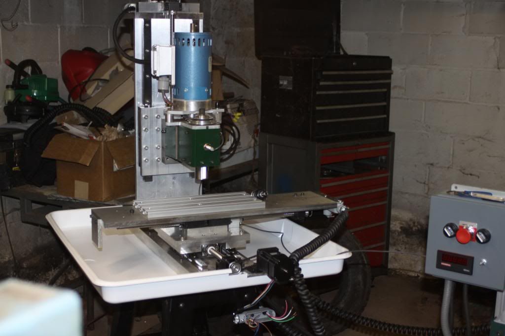
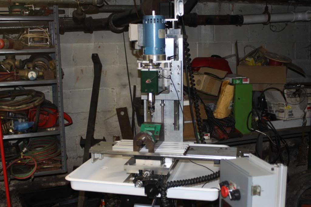
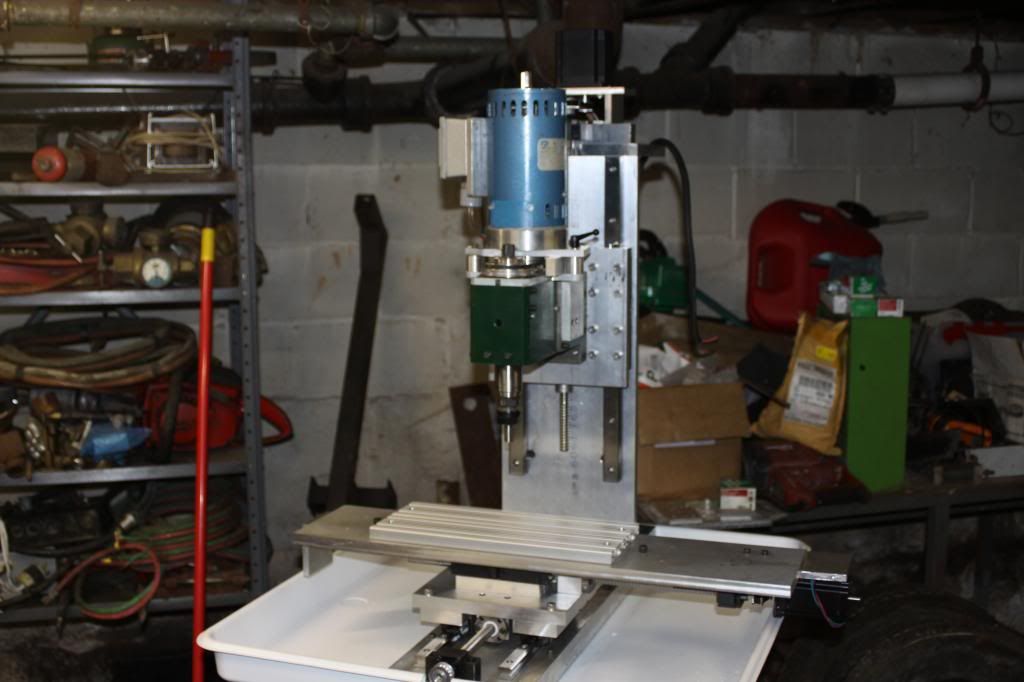
Hello I'm scratch building a small mill with X2 spindle hopefully this is a little more rigid than standard X2 here are a couple pics
Thread: Scratch build small mill
Results 1 to 20 of 52
Hybrid View
-
08-29-2013, 11:39 PM #1
 Registered
- Join Date
- Apr 2013
- Posts
- 97
Scratch build small mill
-
08-30-2013, 03:07 AM #2
Registered
- Join Date
- Aug 2008
- Posts
- 3
That looks pretty cool. What kind of travel are you going for and what are you going to be cutting with it?
-
08-30-2013, 04:47 AM #3
Registered
- Join Date
- Apr 2013
- Posts
- 97
14x7x9 aluminum and mild steel
-
09-10-2013, 10:34 PM #4
Registered
- Join Date
- Apr 2013
- Posts
- 97
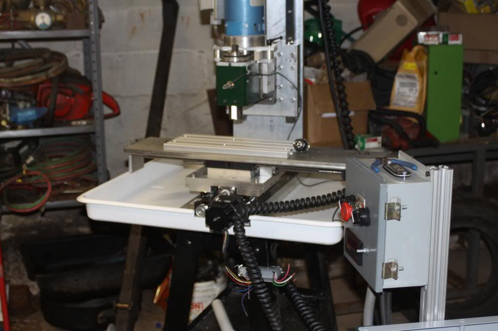
Here Is a couple more pictures I got the Y axis stepper mounted and started on the electrical
-
09-12-2013, 08:25 PM #5
Registered


- Join Date
- Mar 2007
- Posts
- 304
Nice build log, and you definitely are learning a lot by building your own.
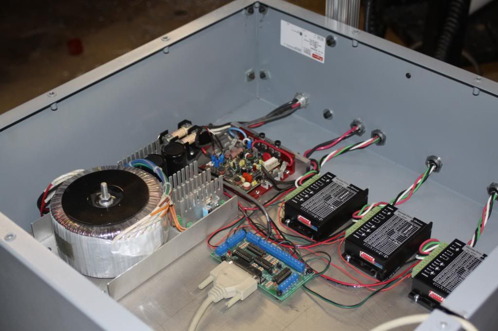
- What Driver Cards are you using?
- Power Supply ?
- Break Out Board ?
Keep up the great work, and please keep posting.
Joewww.CNC-Joe.com
CNC Is Not Just My Passion.. It's My Addiction !!!!
-
09-14-2013, 03:40 AM #6
Registered
- Join Date
- Apr 2013
- Posts
- 97
A little more progress here is a couple more pictures
-
08-30-2013, 12:03 PM #7
Registered
- Join Date
- Aug 2004
- Posts
- 780
Nice effort !
Some opinions ..
Get the spindle much closer the the z-axis.
The z-axis is almost a flat beam.
Make it a box, using the same thickness of metal as the vertical z axis base plate.
Seems to be about 25 mm (Good!).
Milling force (with a 0.5 Hp spindle, using approx 10 mm end mill) is about 50-60 kg (almost a bodyweight).
Put a di in the spindle, indicate against table in x and y, ie horizontally.
Lean on top of the spindle, horizontally, about 60 kg or 150 lbs.
Towards the z.
Does the needle move ? (Ill guess about 1 mm).
The needle movement needs (should) to be less than endmill deflection about 0.04 mm or 2 thousandths or 0.001".
This is for milling metal.
For routers, it looks good.
The section sizes should be proportinal of the third power of free length.
Ie a free length of spindle from z-axis of 100 mm equates to x/100x100x100.
So for 200 mm, its x(200x200x200) ==> 8 times more flexible.
So for every doubling of free length, its 8 time less flexible.
A good result is same free length as is the distance between spindle bearings (ie about 80-100 mm).
Let us know how it works !
-
08-30-2013, 02:18 PM #8
Registered
- Join Date
- Apr 2013
- Posts
- 97
I plan on putting plates on the z-axis and the base is 1 1/2 inch thick this is a hobby mill basically I am trying to do a little better than the standard X2 which the z-axis is a total weak point but I'm trying to get a little more in the Y if I get too much deflection I'll move it in basically the plates are not on on the Z yet because I want to try use the machine to drill them and make parts for mill it will be close to the table and totally engaged on the right angle plate supports the Z the right angle plate that supports the Z is a heavy machining plate 8 x 8 x 18 x 1 inch thick cast-iron I have seen massive amounts of force applied to these right angle plates like mine during machining with stock fastened to them I asked a friend of mine the had any right angle plates and I got this one for free from him the ballscrews are cheap Chinese junk but maybe in the future I will upgrade
-
08-30-2013, 04:00 PM #9
Gold Member
- Join Date
- Jun 2004
- Posts
- 6618
That looks pretty good. Almost the same travel I have on my 80/20 mill. It uses the X2 spindle as well.
Mine is a little beefier if you can call it that. Still aluminum, but extrusions for the base and column. I also used the first iteration of the mill to make parts to better itself.
What I wound up with was a little workhorse that ran almost all the time. I just bought a Novakon Torus to take some of that load off and to do rigid tapping for me.
I still run the 80/20 a couple days a week. It does special and odd jobs that it was already setup to do with tooling plates, etc.
I think you have a very good start on yours. Take a look at my build log. There is info in there about spindles and motor stuff that may be useful.
Good luck with it and keep updating with the upgrades you make. Lee
Lee
-
08-31-2013, 05:00 AM #10
Registered
- Join Date
- Nov 2007
- Posts
- 49
Well, I may be late since you've already done most of it but I must say that while I admire your effort, you're aiming pretty low when it comes about design and materials used.
Aluminium is not good material here. It neither has the strength and elasticity of steel nor the vibration dampening qualities of cast iron. Unless you aim to build just an engraver, in which pretty much anything works, for any real work that stresses the machine aluminium will give in and begin to warp. Tapped holes will begin to distort and bolts will get loose. Keep in mind that at room temperature aluminium is very near the melting point, that's why it is ductile.
In general, If I were to put the effort to make a mill from scratch I would use nothing but cast iron for the structure and steel for parts subject to friction and impact, such as the spindle. Did you know that you can get cast iron in bars, plate, pipe, etc? Search for Dura bar, Versa Bar, etc. Also, casting is not as expensive as people thinks and offers a good opportunity to design the parts very neatly. A quick suggestion would be to make the structure hollow from cast iron plate and use dry sand to fill it. Sand absorbs vibration a little and adds mass to the machine cheaply. This way you drive the resonant frequencies up and it is less prone to chatter.
In a machine tool only two things matter: stiffness and accuracy. Stiffness begins with keeping overhang low in all places. Say, in your design, you have several places in which there is nothing but a plate keeping stuff from flexing. One is the plate that connects the table with the column and the other is the plate you use as a column. Why you decided to keep that plate in the middle of the cast iron angle block and not simply touch the bottom plate and bolt from below is beyond me.
As hanermo said, get used to the idea of analyzing your designs with extreme force applied. Where would it break from if you applied extreme force to it? Reinforce there. Until you get the entire structure to break under force, you can always improve it.
-
08-31-2013, 05:15 AM #11
Gold Member
- Join Date
- Feb 2006
- Posts
- 7063
Only if you consider about 1100 degrees below the melting point to be "near".... Originally Posted by zhagoox

Regards,
Ray L.
-
08-31-2013, 06:21 AM #12
Registered
- Join Date
- Nov 2007
- Posts
- 49
1100 what? See, room temperature is about 300K. Aluminium melts at about 900K and iron at 1800K. 600K vs 1500K seems much closer to the melting point to me. Originally Posted by SCzEngrgGroup
-
09-05-2013, 12:43 AM #13
Member
- Join Date
- Dec 2007
- Posts
- 2134
This makes absolutely no sense to me. For starters, very obviously Ray was talking Fahrenheit, I'm in OZ and use metric but I still got that. Now if your talking Kelvin (which is what the K signifies so far as I'm aware), your statement that Aluminium melts at 900K means when you convert to Celsius, 900K is equal to 3.3 degrees Celcius. And if we're talking kelvin, the difference between 600K and 1500K is infinitesimal when comparing to metals. Originally Posted by zhagoox
As Ray pointed out, if the acknowledged standard for room temperature is ambient 25 degrees Celsius, aluminium melts at 660 degrees Celsius. Significantly above the 3.3 degrees Celsius equivalent of your 900K?
I'm not aware of any iron, or aluminium that melts at that range of temp? And I can't see any way to creatively inflate that figure an additional 656 degrees Celcius before the aluminium will start to melt?
Can you explain this statement of yours please to help us understand?
cheers, IanIt's rumoured that everytime someone buys a TB6560 based board, an engineer cries!
-
09-05-2013, 06:24 PM #14
Registered
- Join Date
- Nov 2007
- Posts
- 49
The melting point of a metal is usually a good indicator of its strength. Let's see: Originally Posted by aarggh
Metal (mohs hardness - melting point)
Lead (1.5 - 600K)
Aluminium (2.75 - 933K)
Iron (4 - 1811K)
Titanium (6 - 1941K)
Tungsten (7.5 - 3695K)
What I was trying to say is that from a physical perspective, all metals are annealed at room temperature to some degree but aluminium is beyond the useful point (for machine tool construction). Iron is nothing spectacular but we never use it pure. We usually use it combined with carbon, making it a cermet. A cermet is different from a regular alloy in that it contains particles of ceramic and not simply metals.
But to be honest, I avoid discussing with people with too much practical emphasis. Practicality revolves around an all or nothing mentality. It doesn't understand concepts such as efficiency. Take a look at this:
Knee mill or Bed Mill
Attachment 199264
Clearly, the person who wrote the article doesn't seem to notice a difference between machining something in line with the column and unsupported. It is equivalent to reduce a heavy (1000-1500 Kg) machine into the levels of rigidity of a small benchtop. If that is acceptable, why to use a Bridgeport style machine at all?
Building aluminium machines is the same. If all what matters to you is that it cuts, fine. But you could even make it out of wood in that place. Or concrete (look at the multimachine concrete lathe). If you want to cut with a decent level of efficiency, you make it of cast iron and design it properly. Such machine will weight the same and probably cost less, but it will remove more material and will do so more accurately.
-
08-31-2013, 11:20 AM #15
Gold Member
- Join Date
- Jun 2004
- Posts
- 6618
I gotta say I do not have any resonance issues in my aluminum based mill. Now to be fair, the entire Z axis is cast iron bolted to a 1" thick aluminum plate. That plate is bolted to the 80/20. It also has a cast iron angle plate backing it up. Then the table ways are also bolted to steel, then aluminum. I have been running it in a semi production mode for several years. I could not do that with a machine close to the melting point.
Granted everything else you say may be true right up to the point that aluminum will not work. It certainly can. Not quite optimal, but surely a valid material to use. My lathe is built using the very same material and technique. It turns fine too.
Lee
-
09-02-2013, 10:19 PM #16
Registered
- Join Date
- Apr 2013
- Posts
- 97
Leeway nice build log I like your machine if I can come close to your results in machining I will be happy I think the other people that commented are very knowledgeable engineers but I think they think this is going to be some high-end high rate of stock removal machine I am dealing with fairly low horsepower and RPM basically I'm just after a hobby machine that's a little stiffer than most and yes I left plenty of ways to strengthen it up whether it be flat stock or 8020 bolted to the sides of the bed and column if they ever looked at a standard x2 base and column I think they would have a heart attack or if the standard X2 was engineered correctly then there's something wrong with the figures the cast-iron that the the Chinese machines are made of is very malleable it actually bends I bought a twisted 7 x 10 lathe bed off eBay real cheap and actually over bent it straight without cracking it
-
09-03-2013, 01:04 AM #17
Gold Member
- Join Date
- May 2005
- Posts
- 3920
Nice machine. I wouldn't worry about the melting point being real close.
-
09-04-2013, 12:22 AM #18
Registered
- Join Date
- Apr 2013
- Posts
- 97
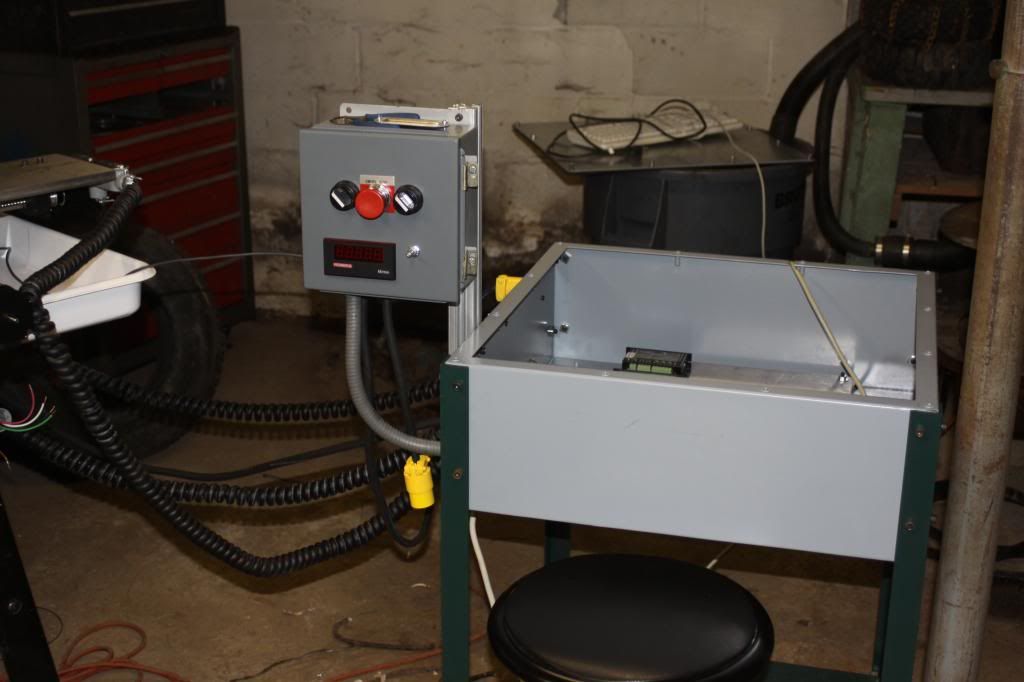
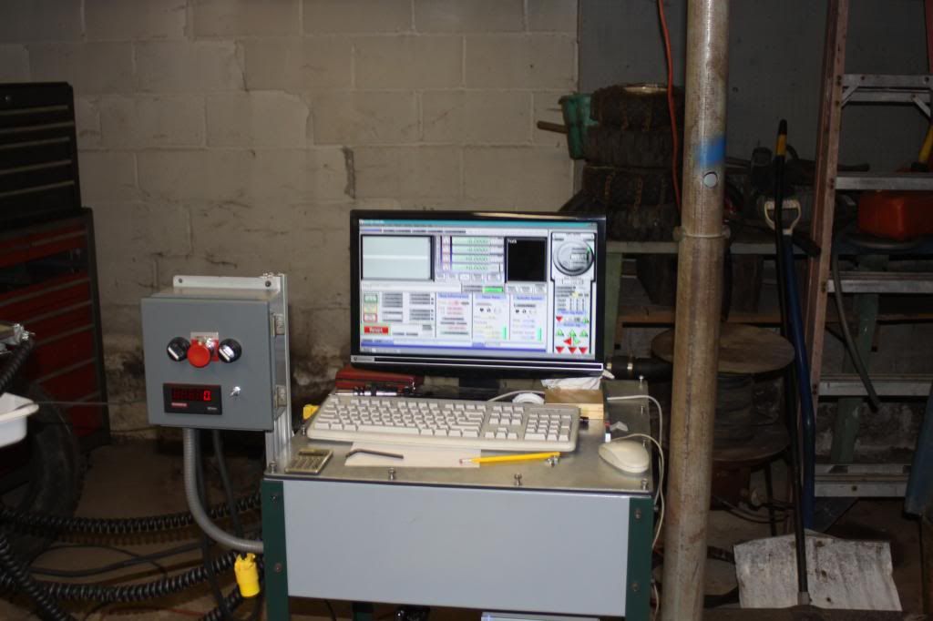
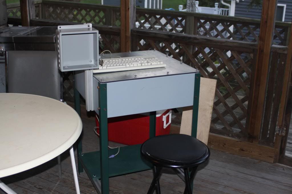
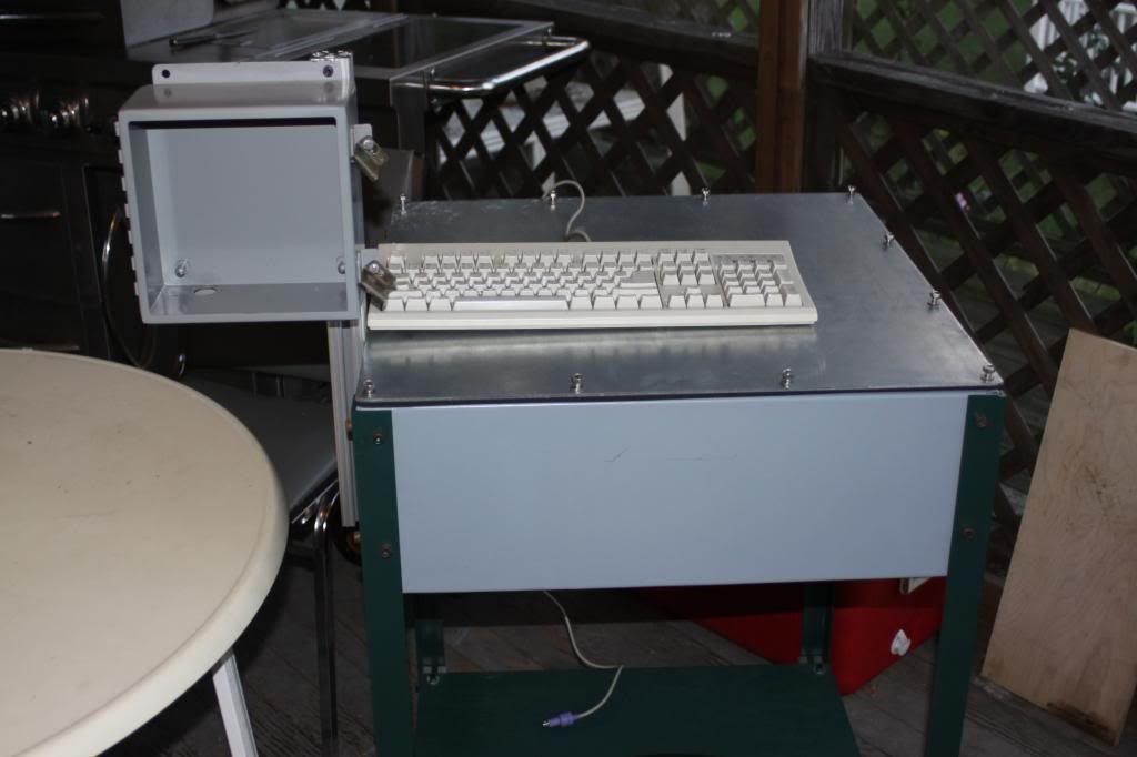
I've been building the electrical enclosure/combination operator station I decided to do it this way seemed to be pretty easy and seems nice and you sit down on a high stool so you can use it standing up or setting down is a couple of pictures Originally Posted by wizard
-
09-03-2013, 06:16 AM #19
Registered
- Join Date
- Nov 2007
- Posts
- 49
I really don't want to be negative, if I'm giving advice is because I really admire your effort. But you know the saying "Whatever is worth doing at all is worth doing well". Originally Posted by dick cnc
Right?
-
09-04-2013, 10:49 PM #20
Registered
- Join Date
- Jan 2010
- Posts
- 485
Did you use MIC-6 plate or just rolled stock aluminum on the mill? If rolled stock was there much warpping/distortion when you milled it to shape? Like when you cut the channel for lead screw clearance.
Nice looking job!!!


 Reply With Quote


Similar Threads
-
Small mill build X2 spindle
By dick cnc in forum Vertical Mill, Lathe Project LogReplies: 7Last Post: 10-23-2013, 12:42 AM -
Looking to build a small table-top CNC mill
By Particle in forum DIY CNC Router Table MachinesReplies: 9Last Post: 10-05-2011, 03:55 PM -
Considering a (first) machine build, a small desktop mill
By footloose in forum Open Source CNC Machine DesignsReplies: 6Last Post: 05-25-2010, 07:12 AM -
Advice on Small CNC Mill - From Scratch or Pre-Built?
By DrCNC in forum Benchtop MachinesReplies: 7Last Post: 11-30-2006, 01:29 PM
