


Goal achieved !!! Hollow spiral in oak , 60mm dia , 180mm length , 2 starts . Like ?
.................................................. ......
Results 61 to 80 of 111
-
10-15-2013, 05:32 PM #61
 Registered
- Join Date
- Feb 2009
- Posts
- 118
-
10-15-2013, 08:54 PM #62
Registered
- Join Date
- Apr 2005
- Posts
- 419
One thing I ran across when looking at timing belt based rotary tables was the servobelt system:
ServoBelt Rotary Stage

Its an incredibly simple and cheap modification that leaves only a few centimeters of belt unsupported. Correctly chosen timing belt profiles have genuinely zero backlash, I believe the AT series has teeth that are carefully oversized as it is designed for high precision linear positioning. The GT series supposedly has zero backlash as well.
-
10-15-2013, 11:11 PM #63
Member
- Join Date
- Jun 2010
- Posts
- 4256
Hi Katran
A couple of things do puzzle me though.
One photo of the big toothed belt pulley shows it as a straight pulley. Another photo shows a large boss on the outer side. What gives here?
Some of the photos and renderings of the driven chuck show three bearings. Given the tolerances associated with any machining, we usually only use two bearings on any shaft. What gives here?
Nice spiral oak, but where's all the sawdust???
Cheers
Roger
-
10-15-2013, 11:21 PM #64
Member
- Join Date
- Jun 2010
- Posts
- 4256
So where did you get that image? I could not find it on the URL you gave. It looks very good. Originally Posted by 691175002
Cheers
Roger
-
10-16-2013, 12:28 AM #65
Registered
- Join Date
- Feb 2009
- Posts
- 118
Man , I cleaned the machine before taking the picture ... that's all . As for that big boss , I have done some modifications to the design , that's Originally Posted by RCaffin

why you see some different things there ... I will make some new renderings , to see in detail what changed .
cheers.
-
10-16-2013, 01:01 AM #66
Member
- Join Date
- Jun 2010
- Posts
- 4256
Hi Katran
Yeah, my wife regularly suggests I clean up my workshop. I do, but then I do some more machining ... :-)
The boss - interested to see the new design. I am learning a lot from this.
Did you have any trouble putting three bearings on the shaft? I have not seen that before.
Cheers
Roger
-
10-16-2013, 01:36 AM #67
Member
- Join Date
- Sep 2006
- Posts
- 6463
Hi Dick, I went deeply into the theory of the involute gear form drive, that is the one with the 14 1/2 deg pressure angle, generated by a point on a circle rolling on a level plane, and one thing came to the fore.....if you have two gears meshed together in intimate contact, when the first gear is driving, both gear faces are in rolling contact for a distance along the pitch circle and above and below the pitch circle known as the addendum and the dedendum, and when the gear train is in the over run position, the second gear now becomes the driver, so having a rolling contact once more but with the back face. Originally Posted by RICHARD ZASTROW
That interprets as both faces have a rolling contact once more, either individually or simultaneously.....the contact area does not change it's strategy when it drives or is driven.
That is the principle I have to make a backlash free drive......that is 100% backlash free.
With zero clearance there can be no reversal of the gears when they are in intimate contact, therefore if no movement can happen in the reverse direction on the over run mode, there is no backlash experienced.....by either gear, or any gear in the train.
I would be the first one to say that precision in manufacture is of prime importance, both in the support for the shafts the gears run on and the profile accuracy of each gear.....the hardness of the material is also important to maintain the integrity of the rolling faces to prevent pitting and surface deterioration.
The meshing of the gears need not be with force, but closeness of contact is a prime factor for eliminating backlash.
If you go to the design of a ball race, you have practically metal to metal contact between the outer race, the balls and the inner race, separated by a film of lubricant, and at the same time, with that small running clearance the ball race is able to carry a heavy load and rotate at high speed without deviating from it's designated path of motion or producing large amounts of heat.
Angular contact, tapered roller and thrust bearings all run with a design factor of zero axial movement, and preloads for this phenomena can be quite high without placing the bearings under destructive stress.
If you cannot measure the end float on a spindle, for all practical purposes you do not have end float.
This would never work for a close meshed zero clearance gear train drive that carried even a light load, but at some speed.......the friction of squeezing the oil film away from the faces of the gear flanks would make the system too hot to handle, but for a 4th axis drive where the speed of rotation is relatively slow, this is not a problem.
Lubrication would have to be of the thinnest of oils, probably using straight Diesel fuel, which is still an oil, so that the accumulated contact faces did not add up the oil film and produce even the smallest amount of backlash when they are squeezed.
Using gears compounded to give 1:60 reduction would not only give a movement that was extremely and constantly accurate, had a high resolution capability, but was maintenance free too, IE no adjustment for wear.
That's how I envisage it, so if the proof is in the pudding, time to get baking.....with the coming event on my advent calendar, I'm gonna need you baby...LOL.
Ian.
-
10-16-2013, 02:02 AM #68
Member
- Join Date
- Sep 2006
- Posts
- 6463
Hi, this looks to be a very simple solution to the rotary table drive. Originally Posted by 691175002
Mike Everman did say that over a length of travel there was some migrating of the belt teeth in the pinion and driven gear when the tolerances for production produced belts varied and was not quite to drawing.
He did state that very good backlashless and positioning results were achieved when a prototype belt was being R&D'd initially, and applied with almost lab standards to get the drive to a high level of accuracy.
This is the same as saying that if you have two rollers rolling together in a friction drive you will have no backlash, but due to slippage the positioning will not be 100% accurate when you go forwards and backwards a number of times.
Ian.
-
10-16-2013, 03:13 AM #69
Member
- Join Date
- Jun 2010
- Posts
- 4256
Um ... I may be quite wrong here, but it sticks in my memory that there is always some sliding contact between the teeth. That may or may not apply to involute gears of course - does any one have any good text-book references?That interprets as both faces have a rolling contact once more, either individually or simultaneously
True, but what happens if there is 1 micron of interference? I worry.With zero clearance there can be no reversal of the gears when they are in intimate contact
Cheers
Roger
-
10-16-2013, 04:59 AM #70
Member
- Join Date
- Sep 2006
- Posts
- 6463
Hi Caff.....I Micron is nothing........that is practically a close encounter .....LOL.....but it is the type of fit you need to ensure the gears don't rattle back on each other with clearance.....there must be zero clearance on all the gears in the train,
Involute gears roll on a flat plane, as in a circle with a point that rolls to form the involute curve.
A circle of infinite radius is a straight line, as in a rack with an inc angle of 29 degrees,
You can generate this curve by rolling a cylinder on a flat surface and watch how a point on the cylinder starts at the bottom and describes a curve as it moves forward with the rotation.
The point I am pushing is that when the gears are closely meshed there will be a smooth motion due to the rolling but no slackness due to the close meshing.
You cannot get this with a worm and worm wheel.....maybe initially, but as the action is a sliding one you need a significant amount of clearance to prevent the two metal surfaces (bronze on steel) seizing to one another.
A hard roller on a hard surface is practically friction free.
Ian.
-
10-16-2013, 05:22 AM #71
Member
- Join Date
- Jun 2010
- Posts
- 4256
Hi Ian
Well, according to several vendors technical notes I consulted, an involute spur gear has both rolling AND sliding contact. EPI Inc have a nice paper on the subject, complete with animation. See for exampleInvolute gears roll on a flat plane, as in a circle with a point that rolls to form the involute curve.
Gear Design Intro, by EPI Inc.
So there has to be enough clearance for sliding.
Cheers
Roger
-
10-16-2013, 09:28 AM #72
Registered
- Join Date
- Feb 2009
- Posts
- 118
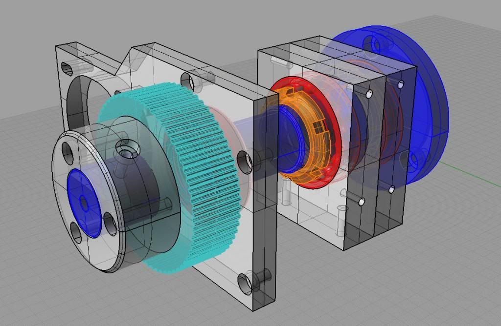
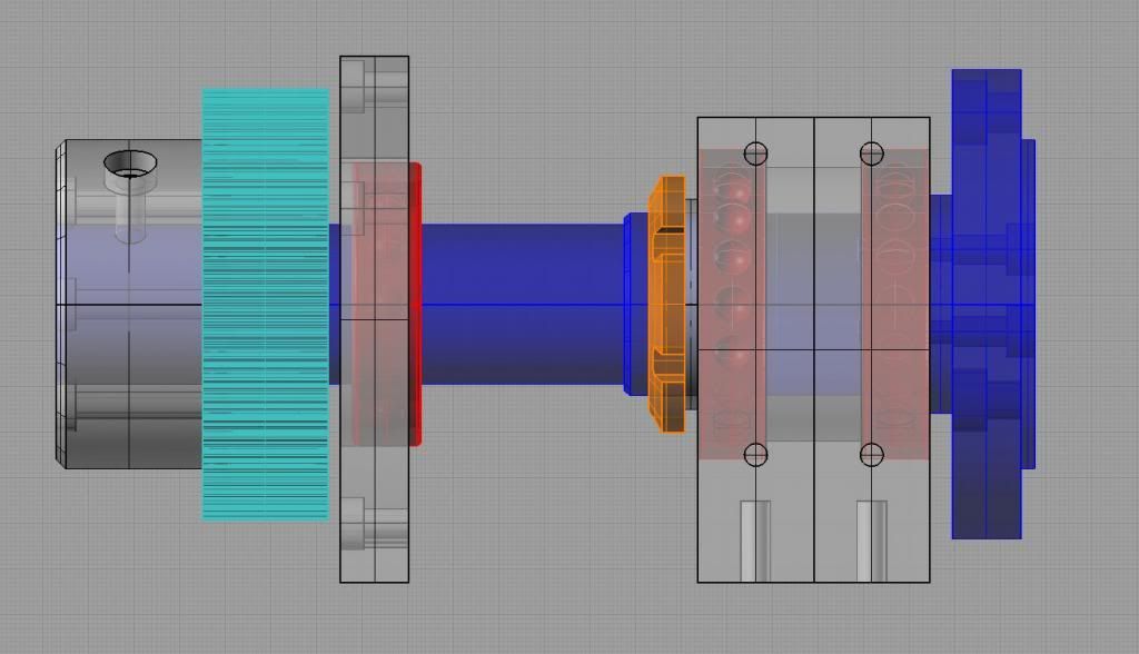
Here are some captures of the design made in Rhino3D ... That big boss is nothing else but a way to bolt that big timing wheel to the Originally Posted by RCaffin
shaft of the spindle ( if you see , there are 3 holes in there , with countersinks... plus a 4"th hole , perpendicular to the main axis , that is
for bolting the boss to the shaft ... ) . Is like this : the timing wheel is spinning freely on that shaft , with a minimum clearance ( about 0.1mm ) .
The wheel is bolted to the boss with three bolts , then the boss is bolted to the shaft ... )
Three bearings on the shaft ... well , it seems to me that this setup is far more rigid and sturdy than 2 bearings only setup ... The angular
bearing are there to eliminate any play ( axial and longitudinal ) , but is not a good idea to preload the bearings to much ... just enough so the
assembly turns fairly free ... Therefore , when you tension the timing belt , is possible to pull the shaft ... and that's bad news for
the TIR of the assembly . To correct that , I put a third bearing on the shaft , so all the force applied by the tensioning belt is much beter distributed ...
I hope that you can understand my explanation ... my english is not that good , is hard to explain technical stuff in a foreign language ...
P.S. You need to remember that the goal here is study only ... nothing fancy or expensive ( yet ... ) . I had to use whatever scrap material I had
in my shop , without spending too much ... I only paid for the timing components and stepper motor , everything else was scrap and salvage ...
In my next 4"th axis project , I will make a much more elaborate design , the budget will be around 1500USD , precision components and so on ...
cheers.
.................................................. .............
-
10-16-2013, 10:19 AM #73
Member
- Join Date
- Jun 2010
- Posts
- 4256
OK, understood.That big boss is nothing else but a way to bolt that big timing wheel to the shaft of the spindle
Oh, it probably is. Takes very good machining to make it work.Three bearings on the shaft ... well , it seems to me that this setup is far more rigid and sturdy than 2 bearings only setup
Did you think about just having one solid bearing at the chuck end?
Um - I have just worked out why you hqave 3: longitudonal play. Hum ... neat.
Your English and explanations are better than I get from some 'English as a FIRST language' speakers.I hope that you can understand my explanation ... my english is not that good
Wish I had that much 'scrap' aluminium to play with! :-)I had to use whatever scrap material I had in my shop , without spending too much
What alloy, if you know? We can buy 6061 easily enough, but it machines poorly. I have some 6082 plate which is nearly as good as 2011.
Meanwhile, my CNC has a jammed ball nut on the X axis. Sigh.
Cheers
Roger
-
10-16-2013, 11:17 AM #74
Registered
- Join Date
- Feb 2009
- Posts
- 118
Thanks Roger ,
I own a pretty good quality lathe ... SP165 Pinacho , made in Spain , toolroom precision ... so is not a very hard job to make a spindle
shaft at correct specs .
I do have a lot of aluminium scrap laying around my shop ... from my other projects . Mostly MIC-6 6061. My cnc router is capable to machine
this alloy very easily ( with a 12mm endmill I can cut at 2-3mm DOC with 30mm/sec feed , and stay in precision parameters -0.025mm/0,001inch ) .
By the way , this cnc router is also a DIY project of mine , finished last winter ... If you like , I can upload a series of pics of the machine ...
cheers.
-
10-16-2013, 11:30 AM #75
Registered
- Join Date
- Feb 2009
- Posts
- 118
I only work with 6061 T6 ... actually , is MIC-6 ( has the surfaces milled from the factory , the thickness is controlled and stable ) . I tried some 7075 also , Originally Posted by RCaffin
but my endmills were not very happy ... In Romania is hard to find good quality aluminium alloy , I had to buy all of my plates from ebay , at a very
high price ( shipping to Europe is expensive ... ) .
If you use a little WD-40 when machining 6061 , you will get a very nice finish ... try not to go too deep ( max. 0.8-1mm DOC ) , high feed speeds ( min.30mm.sec )
and around 8000-10.000 rpm . A good quality milling motor is essential ( HF motor , 18.000 rpm , min. 1,5Kw , controlled by a VFD , with a TIR of max. 0.01mm ) .
cheers.
-
10-16-2013, 04:39 PM #76
Member
- Join Date
- Sep 2006
- Posts
- 6463
Hi Caff, thanks for the very detailed explanation of the Involute gear principle, much better than the ones I have read about over the years. Originally Posted by RCaffin
Looking at the animated display, it appears that the gear tooth tip is sliding when it is almost out of mesh with the second gear, but as the main driving force at that moment is being exerted by the next gear tooth entering the mesh in a rolling motion, I don't think I will worry about that end bit.
It is present as a late event in any gear drive for any gear box having clearance between the teeth and running at high speed, and if it does no harm in that situation it won't in the 4th axis design I have.
There is not that much force present in a 4th axis drive, so a bit of tightness in the mesh is better than a smidgeon of looseness, and as long as the tightness is very slight I think the drive with compounded gears will give good service without any dire consequences.
This type of thinking would not suit a drive that was rotating at speed due to friction becoming a problem, but in higher speed drives the presence of backlash (gear tooth clearance) is not a design flaw......you cannot have both worlds with gear drives, and for a 4th axis the tightness of the gear mesh would be my preference, otherwise if you cannot control the mesh tightness you may as well use a worm and worm wheel set-up.
I got the results I needed to propose the design by removing the banjo gear carrier on my lathe and although the gears are slack on their shafts, when they were meshed fairly closely I could not detect backlash at the beginning and end of a 3 gear compound set-up, so some experimenting is needed to make a drive as I envisage it.
It is quite possible that a set of Nylon gears would be able to mesh tightly without even having any lubrication and as they are of a resilient nature and the gear teeth are mostly of a rolling contact, this may be the way to go.
You can cut Nylon gears very easily with a single tooth fly cutter ground to the tooth form, but proper involute gear cutters with the right tooth form are not all that dear to buy on EBAY.
Ian.
-
10-16-2013, 05:12 PM #77
Registered
- Join Date
- Mar 2006
- Posts
- 2712
Ian, I was employed by a gear manufacturer for a number of years. They were pioneers in the production of "plastic" gears. The plastic gears function was to be sacrificial items between more expensive metal gears. As you stated, they do not require lubrication. However they do wear easily and were replaced periodically.
Unless the axis is used for positioning only or very light machining, the gears will see substantial forces. This is especially true in milling things like steel contouring.
Personally, I'd like to see an epicyclical gear reduction used on an axis drive. See if it proved my theory of compensating variables.LOL
Dick Z
ps, I'm still involved with the gear industry, my cohorts in crime and I design an build gear cutting machines. One is the 40 year old "wizz kid" that wrote the software for 8-axis CNC hobbers, shapers, multi thread grinding wheel dresser for machine like Rieshauer type gear grinders. Fun stuff.DZASTR
-
10-16-2013, 05:38 PM #78
Member
- Join Date
- Sep 2006
- Posts
- 6463
Hi Katran, in the 4th axis design you've made.....(very nice bit of machining too)....there was some mention of using only 2 bearings for the spindle, but as you have the two main bearings right at the chuck end this would not work with a strong belt pull as has been noted.
However if the box had been made with the two end plates bored for the angular contact bearings and just plain end caps used to apply the preload with a spacer on the shaft between the bearing inner races etc, then the 2 bearing method would work too as the only part under load from the belt tension would be the short piece sticking out of the end angular bearing cap that the pulley is mounted on.
The shaft would be retained in the bearings by a threaded collar at the very end of the shaft, pressing against the face of the pulley which in turn is pressed against the inner race of the end bearing with a short sleeve.
There is no need to go to conventional spindle design for a 4th axis with the 3 bearing configuration of 2 angular contacts at the chuck end and a plain radial at the other end as this is not a spindle per se, but a drive shaft with low radial forces from the side thrust of the cutter and practically no axial forces to need preloaded bearings, like mill spindles.
In this instance I think that just 2 double row sealed radial bearings, one either end, held in position with caps would still be sufficient to maintain shaft integrity both in the axial direction and the radial one.
This would simplify construction and also allow bearings with large bores and smaller OD's so that a shaft with a large bore can pass material through it for those spindles with small diams and long lengths, when only the end area is being worked on.
The bore in a 100mm chuck can pass about 35mm if my memory serves, so a shaft with bearings having 45mm bores can have a bore of 35mm too, and a 5mm wall thickness for the shaft is more than strong enough for a 4th axis.
One question, why was the box not made from steel all welded together and machined all over.....much cheaper?
When I made my lathe in the late 60's I used two pieces of channel iron welded together with two 12mm thick end plates welded on, then machined the whole lot all over.
The box was bored in the lathe to take two bearing cups.
Bearings were taper roller and held in the bearing cups inserted in the end plates.
I think I will use this method again as it worked so well previously and is relatively easy to make, but instead of channel iron I might use thick wall square tubing, about 100mm square, end plates welded on and a 20mm piece of steel for the base welded on too.
I prefer to work with steel than aluminium any day.....steel can be welded to give a composite structure, but aluminium needs to be screwed together, very time consuming, or be carved from a solid block or casting, both quite expensive.
Ian.
-
10-16-2013, 05:54 PM #79
Member
- Join Date
- Sep 2006
- Posts
- 6463
Hi Dick.......plastic gears....hmmmm, I think that for the 4th axis this might be a solution as the forces are not all that great, and if a belt drive can handle the forces so can a plastic gear. Originally Posted by RICHARD ZASTROW
I recently made some gears from a green type "engineering" plastic and they work OK in the screw cutting train with the other cast iron gears, yeah it's an old lathe, 1920/30's vintage.
It's all very hypothetical at the moment, but experimenting will have to done if I want to enter the 4th dimension....LOL.
BTW, I'd hate to have to try and make an epicyclical gear box and get the gears to mesh tightly......the ring gear would be a nightmare.
I think it is bad enough designing the 1:60 ratio geared 4th axis I have in mind at the moment.
Ian.
-
10-16-2013, 09:30 PM #80
Member
- Join Date
- Jun 2010
- Posts
- 4256
Ah, you're a lucky man! My gear is smaller, and the X axis on my CNC is currently jamming. Something has got into the ball nut, so I will have to strip it right down. Sigh.SP165 Pinacho , made in Spain , toolroom precision
I do have a lot of aluminium scrap laying around my shop ... from my other projects
Cheers
Roger


 Reply With Quote

Similar Threads
-
Convert Gantry to Belt Driven Need little Help
By dbtoutfit in forum DIY CNC Router Table MachinesReplies: 5Last Post: 03-10-2013, 07:45 PM -
belt or gear driven?
By mikeph in forum Bridgeport / Hardinge MillsReplies: 2Last Post: 11-24-2011, 07:18 AM -
direct driven or belt driven
By jeremy0203 in forum Benchtop MachinesReplies: 5Last Post: 07-27-2011, 05:23 AM -
belt driven CNC
By jwest in forum DIY CNC Router Table MachinesReplies: 1Last Post: 11-29-2008, 11:10 PM -
Belt driven screw ?
By tomcat47 in forum Linear and Rotary MotionReplies: 10Last Post: 01-29-2007, 05:20 PM
