


I deny all expertise on the subject, but it does stick in my mind that chain drives have a LOT more rattle and backlash than a good toothed belt. It's all those sleeves at the junctions - none of them are 'tight' over the pins. Maybe if you had a LOT of tension on the chain you might eliminate most of the backlash, but that would be leaning on the bearings fairly hard.would a conventional chain drive be more effective than a resilient toothed belt for the backlash prevention side?
My 2c.
Cheers
Roger
Results 41 to 60 of 111
-
10-12-2013, 05:05 AM #41
 Member
- Join Date
- Jun 2010
- Posts
- 4256
-
10-12-2013, 06:52 AM #42
Member
- Join Date
- Sep 2006
- Posts
- 6463
Hi Caff, I agree on that observation, but only when the centres of the drives are apart like a bike with a long chain that is subject to gravity and will sag in the middle which is like a spring effect.
In that case if the centres were in a vertical plane there would be no sag, but the whip in the chain would act as a spring and so need excessive force to keep the slack from occurring.
I think that if chain sprockets are spaced close together this might not happen, but how tight does the chain need to be to eliminate all slack and so backlash but still allow a smooth rotation......chain, being mechanically connected, is not subject to stretching like a rubber belt.
I have a selection of chain pitches and some chain sprockets in my goodies box so I might make a test set-up and see if the drive can be effective.
Ian.
-
10-12-2013, 09:41 AM #43
Member
- Join Date
- Jun 2010
- Posts
- 4256
Hi Ian
What? You are going to conduct an experiment? But that is against the rules for armchair debating!so I might make a test set-up and see if the drive can be effective.
Yeah - it would be interesting to try it. My doubts are due to the general disparagement given to chain drives for CNC systems of any accuracy, but who knows? If you have the bits already, no charge for the test. We await the results.
Dunno whether those toothed belts stretch like a 'rubber belt'. They are often reinforced with either steel cord or Kevlar cord, and very non-stretch.not subject to stretching like a rubber belt.
cheers
Roger
-
10-12-2013, 11:04 AM #44
Member
- Join Date
- Sep 2006
- Posts
- 6463
Hi Caff......that sounds very promising , the non stretch characteristic.
I have the feeling that to get to the "non stretch any more" state you have to really get them tight, that impacts on the tooth area as the fit to the pulley teeth is anything but precision....IE, tensioning really tightly makes the pitch of the teeth on the belt expand linearly and so the tooth pitch on the belt will be out of pitch to the pulley.
It will drive as the teeth engage the pulley grooves, but in my opinion it's not too precise, never was designed for that purpose but only for positive driving without slipping, backlash elimination was never in the picture and if it shows any characteristics of a migrating tendency in the tooth drive you have what can be compared to backlash.
I am thinking for my own purpose mainly in the direction of compounded gear driving to get positive precise backlash free positioning, and toothed belts and chain drive is just an alternative "think it might work" situation.
It's possible that if a toothed belt with square sectioned teeth engaged a pulley with tooth gaps that were tapered you might get a wedging effect, but you'd still have to tension it tight and with that the pitch would vary as it can.....gears don't have to be tightly bound to get zero clearance and still run freely.....they are designed for a rolling contact without high force for engagement, and the thinnest of thin oils will lubricate them......for a 4th axis the rotary loading is not all that extreme from the cutter side thrust, even for steel as it's under CNC conditions and the DBMC principle is in play here.
Anyone who does CNC and needs to resort to heavy roughing cuts with a 4th axis is off his trolley and totally missed the plot.
100% for certain, you would not take heavy roughing cuts on a 4th axis with a belt drive....ever, and expect to produce any work worthy to write home about.
I expect for light cuts with engraving type cutters the loading is minimal so nothing in that case will effect the drive or experience the effects of backlash.
Ian.
-
10-12-2013, 11:35 AM #45
Member
- Join Date
- Jun 2010
- Posts
- 4256
It's actually a major design feature of many types of timing belts, especially for positioning use.that sounds very promising , the non stretch characteristic.
Not as far as I know; it is actually the other way around. If you have the toothed belt loose it can skip over teeth and rattle something awful. (Been there...) The instructions usually tell you to put some tension on the belt to get the belt teeth to bed into the pulley properly. A certain amount of tension is required, and you can buy tension guages just for this. You can also get on-line tension meters which work while the system is running.I have the feeling that to get to the "non stretch any more" state you have to really get them tight, that impacts on the tooth area as the fit to the pulley teeth is anything but precision....IE, tensioning really tightly makes the pitch of the teeth on the belt expand linearly and so the tooth pitch on the belt will be out of pitch to the pulley.
That may have been the case 50 years ago, but not today. Modern toothed belts designed for positioning are are very common in industry, and perform very well. I know there are applications which are only concerned with power transmission, but that's really a different sort of belt entirely. My non-CNC lathe uses a Gates PowerBand belt on the spindle which looks toothed, but the pulleys have no teeth.It will drive as the teeth engage the pulley grooves, but in my opinion it's not too precise, never was designed for that purpose but only for positive driving without slipping, backlash elimination was never in the picture and if it shows any characteristics of a migrating tendency in the tooth drive you have what can be compared to backlash.
Oh no, no! Good toothed belts have a carefully defined tooth profile which matches the equally carefully defined profile on the pulleys so there is full wedging without backlash. I dare say after many years a belt or a pulley might wear to the point of needed replacement, but that takes a long time.It's possible that if a toothed belt with square sectioned teeth engaged a pulley with tooth gaps that were tapered you might get a wedging effect, but you'd still have to tension it tight
My CNC uses toothed belts on all axes, and has around 20 micron backlash or maybe a shade less. Travelling in one direction it is reproducible to better than 10 microns. But it only gets that with the right tension on the belts.
Fair enough, but maybe we can live with a lighter duty sometimes.100% for certain, you would not take heavy roughing cuts on a 4th axis with a belt drive....ever, and expect to produce any work worthy to write home about.
Cheers
PS: Yes, I have built a number of 'industrial-sized' robot systems using toothed belts on the drives, I service my own CNC machine, and no, I do not have any connection at all to any suppplier of toothed belts.
-
10-12-2013, 01:09 PM #46
Registered
- Join Date
- Feb 2009
- Posts
- 118
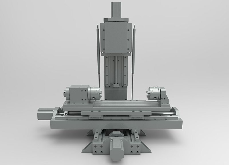
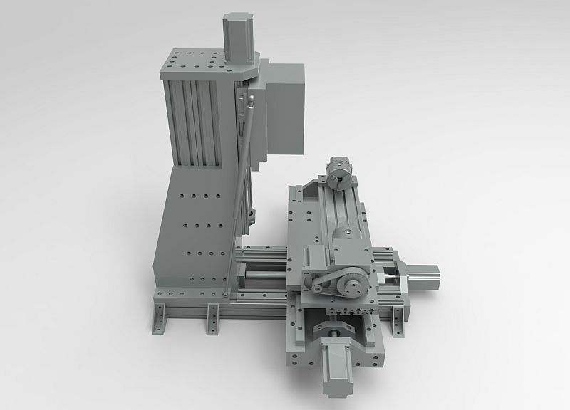
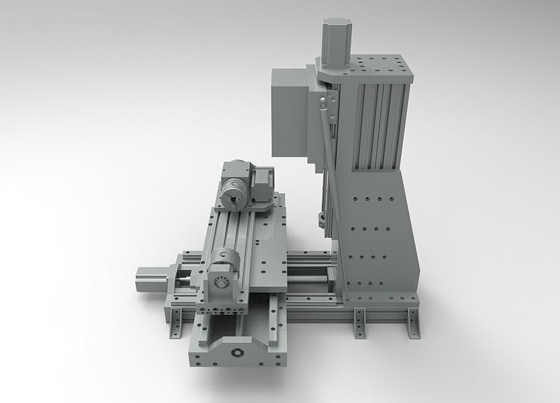
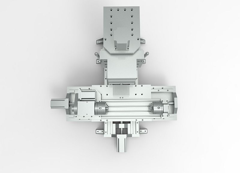
O.K guys ... this is it !!! First test , no B.S , no advance preparing , no nothing ...just played with the MDI , no G-code .
Aligned the fixture fairly true and straight ( around 0.05mm deviation in all directions ) ...this is the best I could do for now ... I really
think that it can be aligned true and straight at 0.01 , but it takes time , Red-Bull and tobacco ...
So , 4mm end mill , 6000rpm , 0.4mm DOC , F2000 feed ( don't know how much is that in mm , I could calculate but I 'm lazy ... )
It vibrates a bit at the far end of the cylinder ( I know , is not correct to have more than 1,5 x diameter sticking out of the chuck )
I am pretty sure that I can be more aggressive ( 10mm endmill , 0.8-1mm DOC ) , but I have to support the end in the rotating chuck ...
Check it out ...
20131012 143909 - YouTube
<iframe width="420" height="315" src="//www.youtube.com/embed/UiFid60Wf60" frameborder="0" allowfullscreen></iframe>
.................................................. .................
-
10-12-2013, 01:26 PM #47
Member
- Join Date
- Jan 2005
- Posts
- 15362
Katran
Just as you say, support the end of the tube with your tail stock, & all will be good, with that amount of unsupported cutting, the vibration you are seeing at the end would happen even with a pro built 4th axes on a big machining centre, Great jobMactec54
-
10-12-2013, 01:42 PM #48
Registered
- Join Date
- Aug 2011
- Posts
- 21
very nice!!
hardy wait the lathe project....
-
10-12-2013, 01:57 PM #49
Member
- Join Date
- Jan 2005
- Posts
- 15362
I think you should build one, with your chain drive idea Originally Posted by handlewanker

I can tell you now it will be a dismal out come, with a chain drive, With the right timing belts used you can have zero Backlash, as far as the timing belt goes, they can also do what ever roughing they want with no affect with using the timing belt, the only thing that can prevent heavy roughing is the power of the spindle & the drive motors, you can rough cut to the max of the motors & spindle, the timing belt will be the least of the problems
Check the GT2 series timing belts made by Gates, Zero Backlash, these have been around for years, it seems you are living in a vacuumMactec54
-
10-12-2013, 04:29 PM #50
Registered
- Join Date
- Feb 2009
- Posts
- 118
Thanks , I appreciate the imput ... , Originally Posted by handlewanker
Look at the pictures . The fixture will never hit anything on that mill ... I already tested .
-
10-12-2013, 05:18 PM #51
Member
- Join Date
- Sep 2006
- Posts
- 6463
Hi, thanks for the info, I'll revise my thinking.......I think the chain drive idea is a bit radical too........and your belt drive appears to be working OK.
Is there a real need for a 1:60 worm drive type head or would the 1:6 belt drive be sufficient, coupled to a stepper motor of 1,000 steps or so.......can't find any information as to what minimum resolution before the stepper is OK.
I've been working on a plan for a 1:60 reduction before the stepper, but if this is overkill for everyday use I'll revert to 1:6 thinking.......that's a lot easier anyway.
Ian.
-
10-12-2013, 09:50 PM #52
Member
- Join Date
- Jun 2010
- Posts
- 4256
Hi Katran
OK, I am seriously impressed. A lovely bit of work.
Cheers
Roger
-
10-12-2013, 09:59 PM #53
Member
- Join Date
- Jun 2010
- Posts
- 4256
Calculate out what 1 step from the stepper motor will give you around a (say) 50 mm circumference at whatever reduction. Is that resolution enough? Originally Posted by handlewanker
The belt drive will introduce very little backlash itself, but you are limited to the small pulley ratio you can get. A worm drive will give you much more resolution, but at the cost of some backlash. Trade-off. Which is why they make things like Harmonic Drives. Fame and fortune awaits he who invents a simpler solution.
Cheers
Roger
-
10-13-2013, 08:39 AM #54
Registered
- Join Date
- Feb 2009
- Posts
- 118
Yo ...Thanks a lot man ... I appreciate it . Originally Posted by RCaffin
belt drive / worm drive / harmonic drive ... guys , I am pretty sure that a 6/1 belt drive system will do just fine for a hobby user . My assembly
will take light cuts in aluminium ( 6-8mm endmill , 0.6-0.8mm DOC at 30mm/sec ) , no problems . As for backlash , if you stretch/tension that
belt correctly , it almost disappears completely ...
If you need a super precision mechanism , you have to use harmonic drives ... but not a little one . You need a drive that will take al least
30-40N/m of torque without slipping ... and those drives are expensive , very expensive ... How about a planetary reduction / gearbox ?
I saw something like this on ebay :
New Parker PX34 005 S2 Nema34 Planetary GearHead Gearbox 5 1 Ratio CNC Servo | eBay
Those gears have very little backlash ( 5-8 arcmin ) , and the price is not too high ...
.................................................. .................................................. ...................
-
10-13-2013, 09:47 AM #55
Member
- Join Date
- Sep 2006
- Posts
- 6463
He He, did I hear gears for a reduction.....I'm currently working on a design using 4 sets of gears in a compound configuration to give a 1:60 reduction, but mainly and more importantly to eliminate backlash completely, as in zero, simply because of the popular worm drive designs that will always have backlash just so that they can work......a worm drive that is totally backlash free is so tight it is very difficult to move it and this leads to further uneven wear.
I think that with the size of the current belt drive layouts, the gearbox arrangement I have in mind would not be out of place.
Gears are designed to mesh with rolling contact, so that means if they are closely meshed, IE metal to metal, there will be no backlash and a thin lube will ensure they do not seize up.....hardened gears are necessary anyway.
I don't think this is a new idea, I just haven't seen it in any form for backlash elimination over the years.
You get small electric clock timer drives that have multi compounded gear trains for the timing reduction, but they are not orientated to backlash elimination and are mainly geared towards reducing a tiny electric motor drive to mins and secs of movement in one direction only......they also have a small amount of clearance between the gears, a design concept which is not suitable for a CNC type concept.
As the CNC 4th axis is a relatively slow drive mechanism, close meshed gears might be the answer to the problem.
It would be interesting to see if plastic gears would work better as they can be in close contact without experiencing undue stress.
That's where I'm at in my thinking for a solution.
Ian.
-
10-13-2013, 10:13 AM #56
Member
- Join Date
- Jun 2010
- Posts
- 4256
Just for the record, it might be worth while quoting from the Gates manual.
Backlash: Backlash in a synchronous belt drive results
from clearance between the belt teeth and the sprocket
grooves. This clearance is needed to allow the belt teeth to
enter and exit the grooves smoothly with a minimum of
interference. The amount of clearance necessary depends
upon the belt tooth profile. PowerGrip® Timing Belt Drives
are known for having relatively little backlash. PowerGrip®
HTD® Drives have improved torque carrying capability and
resist ratcheting, but have a significant amount of backlash.
PowerGrip® GT®2 Drives have considerably improved
torque carrying capability, and backlash characteristics in
between that of PowerGrip HTD and PowerGrip Timing
Drives. In special cases, alterations can be made to drive
systems to further decrease backlash. These alterations
often result in increased belt wear, increased drive noise
and shorter drive life.
.....
The GT tooth profile is based on the tractix mathematical
function. Engineering handbooks describe this function as a
“frictionless” system. This early development by Schiele is
described as an involute form of a catenary. With this system,
the belt and sprocket teeth move substantially tangentially
during entry and exit, thus improving significantly the
belt’s performance characteristics.
............
When installing a Gates PowerGrip® belt:
A. Be sure it is tensioned adequately to prevent tooth
jumping (ratcheting) under the most severe load conditions
which the drive will encounter during operation.
B. Avoid extremely high tension which can reduce belt
life and possibly damage bearings, shafts and other
drive components.
The proper way to check belt tension is to use a tension
tester. Gates has a variety of tension testers, ranging from
the simple spring scale type tester to the sophisticated
Sonic Tension Meter. The spring scale type tester is used
by measuring how much force is required to deflect the belt
at the center of its span by a specified distance (force
deflection method), as shown in the sketch below.
..................
Cheers
Roger
-
10-13-2013, 12:37 PM #57
Member
- Join Date
- Sep 2006
- Posts
- 6463
Hi Caff, I would also think that the tension/defelction is dependent on the distance between the two pulleys.......a very short distance, like the 4th axis application probably would not exhibit any deflection at the centre, whereas a lathe drive with 300mm or 400mm between shafts would show up quite a bit......backlash not being a critical factor there, and the drive only needs enough tension to prevent the teeth of the belt jumping over the pulley teeth.
The specs about the severe loading conditions and subsequent failure aren't a factor with the 4th axis and most of the characteristics for weather, heat, friction and other work related occurrence would not affect 4th axis work, so the belts are very lightly stressed if at all, apart from the effects of over tightening to reduce springing.
I would go with the toothed belt drive if the gear drive I plan to try is impractical, but until I bite that cake who knows.
If I get an earth shattering result with a bunch of gears working in co-ordination from a trial, you people will be the first to know....nothing like public domain critics to expose the weak links in any design....LOL.
When I eventually go CNC for real, I would like to experiment with the eccentrically cycloid type of reduction gear....that has a lot of promise in a relatively simple configuration.
Ian.
-
10-13-2013, 12:56 PM #58
Member
- Join Date
- Jun 2010
- Posts
- 4256
Hi Ian
Tension, no; deflection, yes.the tension/defelction is dependent on the distance between the two pulleys
Looking forward to the results.
Cheers
Roger
-
10-13-2013, 06:22 PM #59
Registered
- Join Date
- Mar 2006
- Posts
- 2712
Ian, The rolling involute form is what makes involute gear teeth work. However, they do require some backlash. The flank of the tooth applying force (front) to the mating tooth uses the rolling action. Without clearance (backlash) the back face of the tooth would slide against the face of the tooth behind it. This would cause the same type of wear as in a worm drive. At least I think so.LOL
Dick ZDZASTR
-
10-14-2013, 12:30 AM #60
Registered
- Join Date
- Jan 2010
- Posts
- 485
@Katran, a good way to tension a belt drive with a short center distance and large ratio is a floating tensioner. It has the added advantage of giving a larger "wrap" of the smaller pulley. This is a drawing of what I mean. Here is the link for it -
Single strap floating belt tensioner

 Reply With Quote


Similar Threads
-
Convert Gantry to Belt Driven Need little Help
By dbtoutfit in forum DIY CNC Router Table MachinesReplies: 5Last Post: 03-10-2013, 07:45 PM -
belt or gear driven?
By mikeph in forum Bridgeport / Hardinge MillsReplies: 2Last Post: 11-24-2011, 07:18 AM -
direct driven or belt driven
By jeremy0203 in forum Benchtop MachinesReplies: 5Last Post: 07-27-2011, 05:23 AM -
belt driven CNC
By jwest in forum DIY CNC Router Table MachinesReplies: 1Last Post: 11-29-2008, 11:10 PM -
Belt driven screw ?
By tomcat47 in forum Linear and Rotary MotionReplies: 10Last Post: 01-29-2007, 05:20 PM
