


I guess the title says it all. Everything I create in Bobcad wants to start cutting in a negative X and Y. I would like to have it out put G code that starts at or near X=0 Y=0 and moves toward X plus and Y plus. I have changed the Axis. I have set the origin at all 4 corners. I am new and do not have anyone that knows CNC. If I move the machine to a spot and zero it at that spot and try to run the code the machine runs the full distance to the negative to start cutting. I could have Mach3 set up wrong. Maybe I need to set the machine that -60" and -30" is=0 so it guts right. Then maybe I am completely wrong. Thank you for any help or insight.
Don
Thread: Move in a Plus direction X and Y
Results 1 to 20 of 26
-
11-13-2013, 02:57 AM #1
 Registered
- Join Date
- Jun 2012
- Posts
- 393
Move in a Plus direction X and Y
The time has come the woodworker said to speak of many things. 0f routers and Wood , chips and paints and stains and CNC and other things.
-
11-13-2013, 03:16 AM #2
Registered
- Join Date
- Aug 2012
- Posts
- 621
When I set up a job for cutting, I place it in the +x, +y. Since I'm basically always cutting a wooden board of some sort, I draw a rectangle of the requisite size, and pick the "Bottom Left" origin in the lower right of the rectangle drawing wizard. The work all goes inside this rectangle, which is the size of my board. Then I hit the Stock wizard, which automatically sizes the stock to this rectangle, and everything ends up in the +X, +Y. It sounds like you're drawing things with 0,0 in the middle of the drawing. Nothing wrong with that, but you need to move it into +x, +y for BobCAD to know you want it there. For BobArt embossments, you need to set the Embossing Stock to Origin:0,0,0, (modified with any offsets you need for placement), and positive values for X and Y. Embossing stock is separate from CAD/CAM stock, so that's important to know.
To sum it up, BobCAD cuts what you tell it to cut. It's up to you to set up your geometry in the place where you want the cutting to happen. Once you do, when you set your work zeroes on the machine, it'll cut where you expect it to.
Luke"All I'm trying to find out is the fellow's name on first base" -- Lou Costello
-
11-13-2013, 03:34 AM #3
Gold Member

- Join Date
- Nov 2009
- Posts
- 4415
Understanding the use of the quadrant sytem is a must. Become familiar with it.
-
11-13-2013, 04:21 AM #4
Member
- Join Date
- Sep 2012
- Posts
- 1195
It sounds like a setup problem in Mach 3. It's possible that you have a work coordinate system active or that you are not correctly zeroing your machine. What do the numbers in the .NC file look like? Normally, you'll see mostly negative Z values and all positive X and Y values.
-
11-13-2013, 05:55 AM #5
Registered
- Join Date
- Jun 2012
- Posts
- 393
The G code shows example Y starts at -8.500 X starts at -6.500 Z moves in a - direction. Originally Posted by mmoe

DonThe time has come the woodworker said to speak of many things. 0f routers and Wood , chips and paints and stains and CNC and other things.
-
11-13-2013, 06:00 AM #6
Registered
- Join Date
- Jun 2012
- Posts
- 393
That was going to be my next route of exploration . I think I now have the info to get it right. I have been starting everything in the 0 0 position. This puts me in the upper right quad. I think I need to be in the lower left. Originally Posted by Fastest1
DonThe time has come the woodworker said to speak of many things. 0f routers and Wood , chips and paints and stains and CNC and other things.
-
11-13-2013, 06:13 AM #7
Gold Member
- Join Date
- Apr 2009
- Posts
- 3376
Here is a link to the Cartesian Coordinate System.
Cartesian coordinate system - Wikipedia, the free encyclopedia
That is what BoB and my Haas use.I do not know on your set-up though.
Are you using your "machine zero" as your zero ?That would be called "home position" on some.
-
11-13-2013, 07:06 PM #8
Registered
- Join Date
- Jun 2012
- Posts
- 393
There are 4 positions on the screen. I use the upper right square. The G Code starts at X+8.0370 Y+8.5970 ans works back. Here is the code.You can run it in Mach3 with no machine running just to see what it does. Or just look at the numbers.
DonThe time has come the woodworker said to speak of many things. 0f routers and Wood , chips and paints and stains and CNC and other things.
-
11-13-2013, 07:12 PM #9
Gold Member
- Join Date
- Nov 2009
- Posts
- 4415
But where do you set your work 0 up?
A lazy man does it twice.
-
11-13-2013, 07:32 PM #10
Member
- Join Date
- Feb 2013
- Posts
- 677
Don,
I assume you're working in inches?
-
11-13-2013, 07:33 PM #11
Member
- Join Date
- Sep 2012
- Posts
- 1195
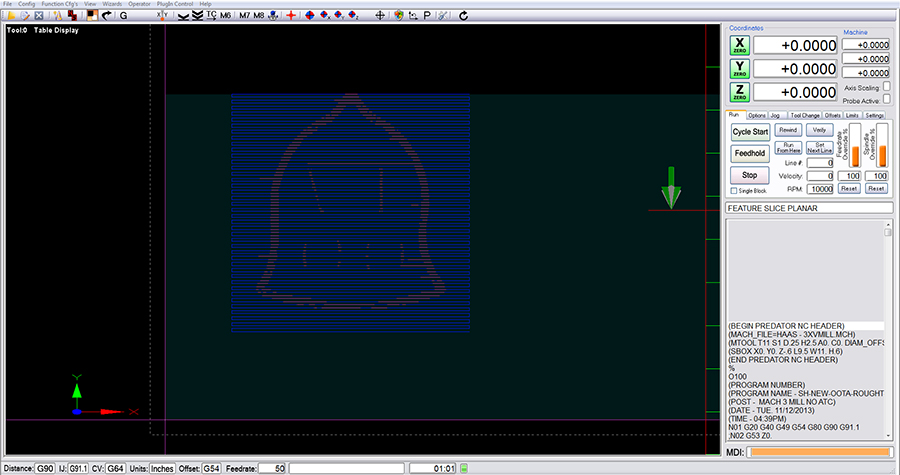
All of the values in the program for X and Y are positive. Earlier you said they were -8.5 and -6.5 and work to the negative. Are you looking at the Mach screen to determine the max/min? It still looks like your Mach setup is backwards to me. Here is the program as it shows in my Mach screen (I use Gerry's screenset, so it looks different, but works the same). As you can see, it's all in the positive X and Y quadrant:
-
11-13-2013, 07:48 PM #12
Gold Member
- Join Date
- Apr 2009
- Posts
- 3376
Hmmmmm........Here is how it back plots.Can you .zip a .bbcd file so we can look more in depth.
As mmoe said all values positive
-
11-13-2013, 08:02 PM #13
Ghost
- Join Date
- Dec 2008
- Posts
- 4548
It appears now what he's describing is that the slice planar toolpath you show there "starts" in the upper right side and ends in the lower right. Maybe he thinks he wants it to start in the left? Originally Posted by mmoe
-
11-13-2013, 10:38 PM #14
Registered
- Join Date
- Jun 2012
- Posts
- 393
Ok so you are getting Plus numbers. And I guess after a bit I got Plus also. I may have stated the question wrong for the part next. Why does the machine make a long diagonal run to the opposite side to start cutting. At this point I do recall I am getting the numbers right. I guess what I would like to know is why start at the high end and comes back to Zero.Or in your set up does it start at Zero Zero and move up the numbers.
Thank You for the help so far. believe it I am learning. Just wish there was someone near by to talk to. I can show and talk a little better then I can write. It could be me but I would think the machine should run 1-2-3-4-5-6 not 0 go to 9-8-7-6-5 and come back. I hope this is clear.
DonThe time has come the woodworker said to speak of many things. 0f routers and Wood , chips and paints and stains and CNC and other things.
-
11-13-2013, 10:59 PM #15
Gold Member
- Join Date
- Apr 2009
- Posts
- 3376
If you look at the pic. I posted a few posts ago,,,The lead in and lead out,among things looks goofy.Really a file will help.After that is sorted,there are some ways to "control" the tool path.
-
11-13-2013, 11:03 PM #16
Member
- Join Date
- Sep 2012
- Posts
- 1195
I'm not sure why it makes any difference really. If it started at 1 and went to 6 (using your example), it still has to return to 0,0,0 at the end of the program, so the same distance is traveled either way. You can think of it like a circle. whether you run around it to the right or the left, you'll still end up back at the start with the same distance traveled. Also, those should be rapid moves, so it will only account for less than .1% of the time the machine is in motion. The resulting part is really all that matters. If there were a finish quality issue with the way the toolpath is running, then you'd have something to be concerned about. Originally Posted by Gallchobhair
It looks like you live in Burien. If that's the same Burien near Seattle, then you live nearby. I live on Beacon Hill, just across I-5 from the north end of Boeing Field, and while I'm not interested in going to look at your machine (more time than I'm willing to commit if I'm being honest), you are welcome to stop by and see how I would set up a job both in Mach and in Bobcad. I think that seeing a machine set up to work properly might be more productive anyways, since you can then determine what you need to change to bring your own machine to the same workflow. I've used many machines over the years and I've set mine up to function like any standard CNC machine. I can also walk you through how a machine should operate in terms of zeroing it out and using work offsets. I'm available mostly weekdays between 8am and 4pm as I'm pretty busy taking kids to hockey and coaching all but two days per week in the evenings/weekends.
-
11-13-2013, 11:08 PM #17
Member
- Join Date
- Sep 2012
- Posts
- 1195
That must be related to the controller the backplot is simulating? On a Mach 3 dry run simulation, the lead in is at the top right and the lead out is at the bottom right. There aren't any moves to the clearance/rapid plane in between, so it's showing as a continuous cut from start to finish on the intended controller. Originally Posted by jrmach
-
11-14-2013, 12:18 AM #18
Ghost
- Join Date
- Dec 2008
- Posts
- 4548
The machine is running the code generated. Originally Posted by Gallchobhair
If that is indeed a slice planar toolpath, then the "edge" of the tool being used in the "percent of tool" and stepover values is determined by "conventional or climb" milling settings on the patterns tab. ticking either one of those will reverse the side the tool enters the stock on....
-
11-14-2013, 12:27 AM #19
Registered
- Join Date
- Jun 2008
- Posts
- 1838
I get exactly that when I run the code through my Predator Backplot, nothing wrong with the code that I can see except the ";" in the code, I deleted them and also changed the G53s to G28G91s, I just find it easier for the way I work. Originally Posted by mmoe
I think the problem is as already pointed out his Mach3 settings, probably just needs the Fixture (G54 in his code) setting up correctly. I`ve also run it through Mach3 get the same results.
Gallchobhair
What do you have set in your G54 fixture in Mach3 ? ?
Easiest test is to "Home" your machine and then jog to the bottom left corner of your stock and write down the X and Y coordinates you get at the "touch off", now go to the "Config" tab and go down to "Fixtures" click on that and your Fixtures (Workoffsets) table will open (See Image below) now check that the coordinates you have written down are the same as those already in the G54 X and Y boxes, if not then manually input them and click the "Save" button. Now set a Z of around -1.0 Inch and click "Save", that should keep your spindle up away from your bed/material.
Attachment 208352
Now load the code in the attached Zip file and it should run correctly in the right place on your machine, assuming also that you have the tool length correctly set, I have just run it and it is OK here, if you have a problem then there is something else wrong with your setup
Attachment 208354
Regards
Rob
:rainfro: :rainfro: :rainfro:
-
11-14-2013, 01:55 AM #20
Registered
- Join Date
- Jun 2012
- Posts
- 393
In Bobcad I have been setting everything to 0,0,0, . I am now using the X+ Y+ quad. I believe LoL. Upper right. This is in answer to Fastest.
The time has come the woodworker said to speak of many things. 0f routers and Wood , chips and paints and stains and CNC and other things.

 Reply With Quote
Similar Threads
-
Stepper Motors Only Move In One Direction???
By lew90nicis in forum DIY CNC Router Table MachinesReplies: 4Last Post: 07-04-2012, 02:52 AM -
x axis will only move 1 direction
By brent48 in forum Stepper Motors / DrivesReplies: 1Last Post: 11-09-2010, 06:25 PM -
KM3P will not move in Y- direction
By BrianP in forum HURCOReplies: 5Last Post: 09-12-2010, 08:01 PM -
cog belts that move when spindle changes direction
By FanucIssues in forum MetalWork DiscussionReplies: 3Last Post: 07-26-2009, 08:42 AM -
x axis will only move one direction
By CATCH22 in forum Mach MillReplies: 2Last Post: 12-17-2007, 03:53 AM
