


In 6061 and 7075, 8" wide by 5" deep. Using the Superfly cutter in passes 2" apart in Y.
My machine's tram in X is nearly perfect and also in Y, but parallelism of the table surface in Y to Y movement is off about .0005" per two inches. So I get little ridges at the overlap.
I've tried shimming the vise a wee bit to bring the work parallel to movement, but that goes against the tram a wee bit so I still end up with a tiny step.
Any ideas on how to accomplish this? I was thinking of grinding that surface on abrasive against a surface plate. I'm fairly new to trying to accomplish more precision than this, so thoughts from the experienced would be greatly appreciated.
Thread: Cutting a flat surface
Results 1 to 20 of 23
-
02-13-2014, 07:19 PM #1
 Registered
- Join Date
- Oct 2010
- Posts
- 136
Cutting a flat surface
-
02-13-2014, 07:40 PM #2
Gold Member
- Join Date
- Jun 2006
- Posts
- 2512
Use a smaller diameter fly-cutter or a 1/2" end-mill.
Phil
-
02-13-2014, 08:13 PM #3
Registered
- Join Date
- Jan 2012
- Posts
- 714
On my machine I have the same problem, I tightened the gib on the Z axis and it helped some. Mine is off a tad still, I use a large face mill so that I can face the entire part in one pass, it doesnt correct the error but it does cause it not to show in the final finish.
mike sr
-
02-13-2014, 08:24 PM #4
Registered
- Join Date
- Oct 2010
- Posts
- 136
Did you make this fly cutter? Five inches seems quite wide for this machine.
-
02-13-2014, 08:49 PM #5
Registered
- Join Date
- Aug 2010
- Posts
- 128
Make sure your spindle is parallel with your z axis. Depending on your machine, it is possible to be in perfect tram but still not have z and spindle in line.
-
02-13-2014, 09:14 PM #6
Registered
- Join Date
- Oct 2010
- Posts
- 136
How would you test for that? Given mine has the Y travel issue, I can't run an indicator down a surface perpendicular to the table.
I have tried using a laser, but that's only so accurate. Starting at the very top and carefully adjusting the laser aim, I find I can run the head all the way down and the dot doesn't move so far as I can measure.
-
02-13-2014, 09:29 PM #7
Registered
- Join Date
- Aug 2010
- Posts
- 128
Try clamping a straight test rod in the spindle and indicate off this as you z up and down.
-
02-13-2014, 09:40 PM #8
Registered
- Join Date
- Oct 2010
- Posts
- 136
Ah, thanks. That I can do. Not that I have a very long known straight rod, but 4" should be enough.
-
02-13-2014, 10:26 PM #9
Registered
- Join Date
- Oct 2010
- Posts
- 136
Set up with a 1/2" ground rod I have in an ER20 collet holder and with no runout measured. Only have a bit over 3" to test but in X and Y the needle doesn't move. A .0001 per tick indicator.
-
02-14-2014, 04:52 AM #10
Registered
- Join Date
- Oct 2010
- Posts
- 136
More adventures. So I clamped an aluminum bar in a vise and cut that in one pass with the Superfly. This of course makes that surface perfectly in tram with the spindle. Then I mounted an indicator in the spindle and moved the table in Y while keeping that indicator on that surface. The tram never changes but the height does. By about 0.001" in 3". This explains the .005ish difference in passes 2" apart.
So now I wonder if more foot tweaking would help? Or is it worth trying to shim the column? Of is that a really bad idea? Or try changing the level of the machine? My table is nearly perfectly level in both directions.
I figured next I will try all this with all four base bolts loosened. Just to see if the base wants to have a different shape than bolting it down gives it.
-
02-14-2014, 09:52 AM #11
Registered
- Join Date
- Jun 2006
- Posts
- 340
Beezle,
There are a number of possible causes of misalignment of the rotational axis to the axes of movement. Z axis gib tightness, out of plane stand pads, column to table, column to base, spindle axis, and a combination of all those. So the aim should be to achieve an alignment that produces the parts within the accuracy tolerance you require.
In your case it seems that what you want is the Superflycutter to not leave a step greater than 0.0005" (?) between passes in the X direction (ie the ZY plane). The swing diameter of that tool is about 4+ inches and therefore you are looking for a tramming accuracy of < 0.0005" in 4" in the ZY plane, a tall order for the machine in the price range of the Tormach. Nevertheless, it can be done in one Z plane while not worrying too much about the alignment in the other.
The following assumptions apply.
1. The Z gibs are properly adjusted as per Tormach User Manual, to minimise any "wobbling" as the flycutter load varies with each rotation.
2. Any rod held in the spindle, used to measure tram, has the same runout over its length and is not rotated between indicating in the ZY and the ZX plane.
3. The tramming is done with the indicator at the same radius of the desired max flycutter pass.
Once the readings are obtained, use the following technique to tram in the readings to the desired limits. This technique was suggested by NYCC, a frequent poster of videos in this forum.
1. Make two jacks each consisting of a 1x1x0.5" bar with 1/2" bolt/screw in centre.
2. Loosen the base hold down nuts to finger tight.
3. Locate a jack at the two front/rear/side feet, depending on which way adjustment is needed.
4. Adjust the jacks until tram is within limits desired/acceptable to you.
This method has the advantages that it is easy to do.
1. The adjustment can be made while indicating in the appropriate position/plane.
2. Indicator is in spindle and at desire tramming radius, and thus it is simple to obtain readings in the other Z plane.
3. No need to find the correctly sized shim.
4. No need to separate base from stand or base from column to insert shims.
5. The column-to-base seating is full width as designed and thus minimises any relative base column movement.
4. Can be adjusted at any time in future.
5. Cheap.
By the way, I used a fine, not coarse pitch for the 1/2 inch bolts; it provides a finer control of adjustment.
Good luck,
Bevin
-
02-14-2014, 02:55 PM #12
Registered
- Join Date
- Oct 2010
- Posts
- 136
This fly cutter is set up for 2.5", not 4". I would like better than 0.0005 in 2". The spec calls for 0.0015 over the entire Y travel. I am getting more like 0.003. The test indicates 0.0005 over the entire travel. I wish!
The problem doesn't appear to be base twist. I've already been through all that. Or the Z gib. The spindle and Z motion are square.
The problem is that Y motion runs uphill away from the column. The column is tilted forward a wee bit. If the table were twisted, this would show up when swinging over the cut surface. But that looks good.
I think I'll try lifting the front of the stand a wee bit and see if that has any effect, but this is what it is. Grinding the surface is no big deal.
-
02-14-2014, 04:32 PM #13
Registered
- Join Date
- Mar 2009
- Posts
- 1863
I have the perfect solution for not getting a step when you surface large parts. I just don't do parts that are that big. I tell my customers "if I can't hold a dozen parts with my hands cupped cupped together, then they're too big and I don't want to do them".
You can buy GOOD PARTS or you can buy CHEAP PARTS, but you can't buy GOOD CHEAP PARTS.
-
02-14-2014, 06:08 PM #14
Registered
- Join Date
- Oct 2010
- Posts
- 136
Not a bad solution. Trouble with this is I am the customer.

-
02-17-2014, 08:47 AM #15
Registered
- Join Date
- Oct 2010
- Posts
- 136
I am gathering parts to build a TTS compatible fly cutter that can do > 5". A few interesting ones exist out there. I think. But they mustn't be very popular as they are rare. One requires a shell mill holder. The other looks pretty cool, but who knows? You can't find a decent image of it online. I will post back here once I get something working (or not).
Precision wise, I fussed over the machine base feet thing and again and got the error reduced a bit, but the best solution for this is simply going to be a really big fly cutter.
-
02-17-2014, 07:51 PM #16
Gold Member
- Join Date
- Jun 2006
- Posts
- 3063
You might want to consider balance when designing and building your large diameter flycutter.
Mike
-
02-17-2014, 09:16 PM #17
Registered
- Join Date
- Oct 2010
- Posts
- 136
Good advice. I am trying two of them, one of which is designed to be balanced. shaped like a "T". The other isn't quite balanced, but I am going to be doing very shallow cuts at as slow a speed as will work. 1000 RPM maybe? Something like that.
-
03-06-2014, 02:22 AM #18
Registered
- Join Date
- Oct 2010
- Posts
- 136
Tried a few products and ended up deciding this is the one. The B-52 fly cutter. This one is 6" in diameter.
Very well balanced with no vibration I can see even at 1500 RPM. I am using it at 1000 RPM and 5 IPM with mist coolant on 6061. The resulting finish is very nice.
Note I pressed a TTS adapter on the shaft.
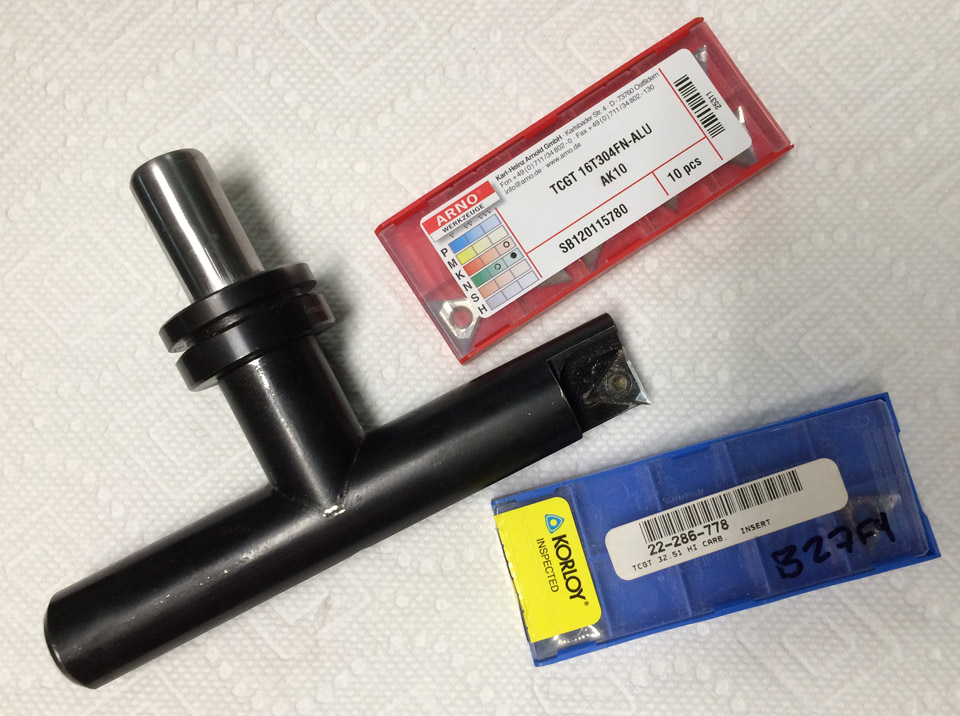
I couldn't find much on these cutters on the web, but it turned out to be a good choice. Uses TCGT 32.51 inserts.
-
03-06-2014, 03:48 AM #19
Registered
- Join Date
- Mar 2009
- Posts
- 1863
I like a cutter called a Shear Hog from AB Tools. I have a 1 inch single flute one that I can run at 3500 RPM 50 IPM and it gives a beautiful finish and I can plunge straight down. They also offer a 1 1/2 inch and a 2 inch that has 3 flutes. When I had my chop, I had a 2 inch 3 fluter and I used to run that at 7,500 to 10,000 RPM, inch and a half wide 1/4 inch DOC and 100 to 250 IPM, but I had 22 horsepower to work with. The biggest problem with the Shear Hog cutters is the price of the inserts. They are about $18.00 each, and they only have 2 corners. You can get inserts with .010, .030 and .062 corner radii, and I think they are available in .125 corner radius. Originally Posted by Beezle

That B52 cutter is a nice cutter, but that tip has to travel a LONG ways around to get back to the part again.
One thing I forgot to mention, if you use the Shear Hog, keep your broom handy because they throw chips everywhere.You can buy GOOD PARTS or you can buy CHEAP PARTS, but you can't buy GOOD CHEAP PARTS.
-
03-06-2014, 04:02 AM #20
Registered
- Join Date
- Oct 2010
- Posts
- 136
Well, the point of this was to make a flat surface with no steps 5" wide. So while I don't care to swing such a wide and heavy tool, it serves this purpose well so far.
I will check out the Shear Hog. I do use the Tormach Superfly a lot and love it.

 Reply With Quote
Similar Threads
-
Possible to bend a flat surface?
By Seitz333 in forum BobCad-CamReplies: 2Last Post: 09-25-2012, 09:52 PM -
How to unroll conical surface flat?
By asterisk in forum Rhino 3DReplies: 5Last Post: 06-08-2012, 10:13 AM -
Synthetic Countertops as flat surface?
By kinghong1970 in forum DIY CNC Router Table MachinesReplies: 8Last Post: 04-21-2012, 06:03 AM -
How to have surface table really 'flat'?
By Sentinel in forum DIY CNC Router Table MachinesReplies: 8Last Post: 04-02-2008, 07:06 AM -
Facing and getting a FLAT surface
By SRT Mike in forum MetalWork DiscussionReplies: 27Last Post: 05-11-2007, 08:22 PM
