


Hello Everyone, I'm in a bit of a jam with this project. (this is the story, the questions are in the second paragraph) I have a Supermax knee mill that had an Anilam Crusader II CNC conversion on it. after much deliberation I decided to go the path of least cost first and try to repair the beast. wrong idea. replacement parts are expensive. I didn't want to waste time and money trying to resurrect an "archaic" machine. so I decided to do what nearly every inquisitive adventurous person would do. Instead of replacing the button matrix and having a machine that is hard to use and time consuming to run I decided to spend a little more money and convert it to run on a Dynomotion Kflop/Kanalog PC based system. After a bit of tinkering I got everything to communicate with each other. glass scales appear to work beautifully. I got all my servos to power up and hold position. (until I power up the k flop/ K analog boards, then they wander. I'm sure that is just a function of tuning.) I have removed ALL of the original Anilam electronics from the head unit. I used the enclosure to house the motion controller and power supply and various interfaces for my glass scales and such. used a PC power supply to juice up the motion controller boards and glass scales independently from the controlling PC. (I heard horror stories about powering it from the PC itself) Finally Mounted a flat screen monitor on the front and now it all looks like it kind of belongs there. I will post pictures of everything if i can figure out how.
Everything has come down to programming this animal and I don't have a CLUE where to start. I have a couple resources with c programming experience that have looked at it but they have no experience when it comes to machinery. so its the blind leading the blind. I have searched rather thoroughly across the internet and haven't found anything too helpful. Does anyone have kind of a "step buy step" type of layout of what has to me done to tune motors and glass scales and program this all to work with Mach 3? I was advised by Tom from Dynomotion, said that this would be the best option because I'm probably not the first or last to need this sort of help. He said that the first step is getting a motor to servo using kmotion.exe. I'm not totally lost as what this means but DOING it is a different story. I would assume that with the versatility of these motion controllers there is no "one way" to do it. Additionally I'm sure I'm missing something rather simple.
I really appreciate any and all help I could get. Thanks to all who have read through this, I will get Pictures up as soon as I can. Hopefully this thread can solve more than just my problems.
Thanks again!
-WT
Results 1 to 20 of 43
-
03-18-2014, 03:16 PM #1
 Registered
- Join Date
- Dec 2013
- Posts
- 27
Anilam/ supermax Frankenstein project using Dynomotion Kflop and Kanalog boards.
-
03-18-2014, 05:21 PM #2
Junior Member
- Join Date
- May 2006
- Posts
- 4045
Hi WT,
The first step is to get KFLOP to servo control one motor. For this to work KFLOP must be able to command motor speed and KFLOP must be able to know encoder position. So start by verifying those two things. You stated you have the machine wired and tested but didn't state how it is wired or how you tested.
I'll assume you have Kanalog DAC0 wired to your X motor amplifier. To test if KFLOP can control the X motor speed do the following:
#1 Run KMotion.exe and open the Console Screen
#2 Power up the System
#3 Enter DAC0=XXX commands to verify you can control motor speed
#4 DAC0=100 should move the motor at ~5% of full speed
#5 DAC0=-100 should move the motor at the same speed in the opposite direction
#6 DAC=0 should nearly stop the motor. It is common to have some small drift. Analog signals always have some amount of noise and offset. This wont matter when the servo is enabled. But to have the servo stop when disabled you should have some means of disabling the amplifier.
To test if KFLOP can know the encoder position I'll assume you have the X axis linear scale wired to the differential inputs on Kanalog A0- A0+ B0- B0+.
#1 open the KMotion.exe Axis Screen
#2 observe the Axis Channel #0's Position Reading and Mark the Axis's Physical Position
#3 move the axis around either manually or with DAC commands listed above
#4 Observe that the axis counts properly up and down
#5 move the axis back to the original marked physical position
#6 observe that the Position Reading is the same (or very close) to the original reading.
If all the above steps worked correctly we are ready to try to enable servo feedback control.
#1 open the KMotion.exe Config/Flash Screen
#2 use Load Channel to load the KanalogInitialPID.mot Configuration
#3 Open the KMotion.exe Step Response Screen
#4 Push the Zero Button
#5 Hold your hand over EStop in case the axis runs away
#6 Push the Enable Button
The axis should now be servoing. If you push the motor or Axis it should attempt to move back to where it was. If there was a runaway then we probably have positive feedback instead of negative feedback. Repeat the steps but after loading KanalogInitialPID.mot change the InputGain0 parameter from 1 to -1.
Let us know how much of this you understand and how far you got with as much descriptive detail as you can.
HTH
RegardsTK
http://dynomotion.com
-
03-19-2014, 03:02 PM #3
Registered
- Join Date
- Dec 2013
- Posts
- 27
TK
All of this is a piece of cake! like I said before it was probably something very simple that I was missing. This is a good thing. There are however, a few variables that will most likely change how this all goes down.
The first 6 steps worked exactly as you said they would! EXCITING STUFF! I was very pleased to try different values in the DAC manual entry in the "counsel screen" and see all three axis moving at respective speeds at different values.
moving on to the second 6... due to the nature of the linear scales they had to be wired in differently. They only had two phase wires. I wired them into the Kflop JP5 port using an ethernet wire and a cool little junction box and pcb from radio shack. They do show up on the axis screen, but in positions 5 6 7 (7-X axis, 6-Y axis, 5-Z axis) so naturally when I went to go enable using the parameters loaded above (I was curious) all three axis decided to move simultaneously in about a 5-10% runaway. Now that that has been enabled I cant figure out how to get back to square one and also whenever I power up the servos they all start running away. I would assume because they aren't getting any feedback. Pictures in about 10 minutes.
Thanks a ton! this is already making me feel like this project will finally get finished and ill have a functioning machine!!!
-
03-19-2014, 03:11 PM #4
Registered
- Join Date
- Dec 2013
- Posts
- 27
Attachment 228800
this is a pic of the beast assembled and booted up.
-
03-19-2014, 03:18 PM #5
Registered
- Join Date
- Dec 2013
- Posts
- 27
Attachment 228802
This is the innards of the "New head unit"
Attachment 228806
This is a closer look at where the axis are wired into the k analog. Inside the junction box for the encoders there is a set of Variable pull down resistors. since the JP5 port is 5 v tolerant but is meant for LVTTL I used these pull down resistors to crank back the output of the glass scales from 5.8v/approx 1.3v to down to exactly 3.3v/approx .25v for the high low signals. for some reason these pictures arent all wanting to attach, I will keep trying.
-
03-19-2014, 05:55 PM #6
Junior Member
- Join Date
- May 2006
- Posts
- 4045
Hi WT,
Very good. I see 2 photos.
To get back to "square one" you can disable the KFLOP Axis Channel. If the Axis Channel is enabled then the servo will be constantly sending DAC commands so any DAC commands you send from the Console Screen will immediately be over written. You can push the "Disable" button on the Step Response Screen to disable the Servo for the Axis Channel. You can check which Axis Channels are enabled on the Axis Screen.
The KanalogInitialPID.mot has the Max Output Limited to 200 DAC counts which is why the runaway occurs at ~10% speed when something is wrong.
I'm not sure why you wired the encoders in reverse order but that should be ok, just a little confusing. After you load the KanalogInitialPID.mot Configuration you will need to change the Input Channel 0 number to match the encoder for the axis. Also the Output Channel for the DAC used for the Axis.
RegardsTK
http://dynomotion.com
-
03-19-2014, 11:23 PM #7
Registered
- Join Date
- Dec 2013
- Posts
- 27
This is obviously a game of baby steps. This is where I get confused. here is what I have very specifically.
the X axis is wired into pin 0 on JP11 on the kanalog (DAC 7)
the Y axis is wired into pin 1 on JP11 on the kanalog (DAC 6)
the Z axis is wired into pin 2 on JP11 on the kanalog (DAC 5)
are these pins on JP11 on the kanalog board corresponding to the channels on the configuration and flash screen?
on the configuration and flash screen:
there is a channel select at the top of the screen. Then, each channel has an input channel and an output channel. The way I'm understanding all of this is the channel select at the top of the config/flash screen selects which motor or in my case which axis we are modifying. (which DAC to modify?) The input channel for that channel would correspond to the number on the axis screen that the numbers change when I move the axis.(this confuses me because when I enable and disable other axis in the config/flash and channels start moving that i didnt think i wanted to move and I don't have encoders wired there.) and the output chooses which pin to send the pwm analog signal to on jp11 on the k analog board. If I'm totally wrong on any of this please correct me.
to me the redundancy in some of the labeling is really confusing. I get 8 channels (0-7 which appear to correspond with the DAC 0-7 which would make sense ) Then each of those have an input and output for each. (Input would be encoders? output would be the pin that you are sending the signal to. (16 of those 0-7 for jp11 and 8-15 for??
 ) these are assumptions and I don't know for sure.
I have my encoders wired into pins 3,4,5,6,7,8 on JP5 (I/O's 38,39,40,41,42,43 respectively) on the KFLOP (not KANALOG). (I soldered the wires in the same order on the pcb in my junction as they were in the ethernet connector, they just happened to be 3-8 instead of 1-6) These are my glass scale encoder output phases. 3/4=Z axis 5/6=Y axis 7/8=X axis (I thought that was 1-6 not 8-3 as it is)
where do these encoders fit in?
I don't understand how to get these to correspond with axis/motor/DAC "channel" that I want them to. I have not been able to find the pattern yet. do I need to go back to college for electrical engineering to understand this or am i going to do this? lastly can i do all of the axis at once or do i need to do one at a time?
Am I way out in left Field?
-WT
-
03-20-2014, 02:25 AM #8
Junior Member
- Join Date
- May 2006
- Posts
- 4045
Hi WT,
Sorry it is so confusing. I think we overused the term "channel". We offer a lot of flexibility where any KFLOP Axis can use any DAC Output or any Encoder Input. Some less common configurations (not yours) even require more than 1 input and more than 1 output. So you need to know how you connected things and KFLOP needs to be informed how things are connected.
There are 3 conceptual things you should understand (Axis, Encoder Input, and DAC Output):
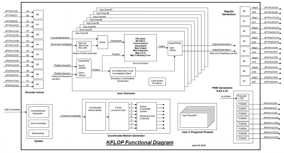
#1 - KFLOP Axis Channel - This is a high level abstract software object in KFLOP used to control some type of motor. You might imagine this to be a little person inside KFLOP that does all the calculations and work. It calculates the position where the motor should be, reads some encoder to see where the motor really is, does the PID calculations to decide how the motor should be driven, and writes the result out to some DAC. KFLOP has 8 of these "people" labeled #0 through #7. Much later when we eventually attempt to run GCode we will also need to define which GCode Motion Word like "X" will be passed to which KFLOP Axis Channel (Using DefineCoordSystem).
#2 - Encoder Input Channel - this is a hardware device that is connected to specific IO Pins that counts encoder signals. KFLOP has 8 of these labled #0 through #7
#3 - DAC Output Channel - this is a hardware device that is connected to specific IO Pins that outputs an analog voltage. Kanalog has 8 of these labled #0 through #7
This Functional Diagram may help your understanding - although it only shows KFLOP and its devices
Now to consider your specific X Y Z situation we must first decide which 3 of the 8 available KFLOP Axis channels to use. For simplicity lets just use #0,#1,#2.
Reading your posts on how you tested the DACs I think you wired to DACs #0,#1,#2. Also from your photo (JP11 pins 1,2,3). Is this true? I will assume it is. I think you made an error in your last post when you incorrectly said:For encoders I think you are wired to #7, #6, #5. If you would have had differential encoders you could have used #0,#1,#2 to make everything really simple. But to use single ended inputs on JP5 only #4,#5,#6,#7 are available. Wiring them in reverse order just adds some confusion. But no worries KFLOP Axis channels can be configured to handle this.the X axis is wired into pin 0 on JP11 on the kanalog (DAC 7)
the Y axis is wired into pin 1 on JP11 on the kanalog (DAC 6)
the Z axis is wired into pin 2 on JP11 on the kanalog (DAC 5)
By default Axis (little person) #5 is expecting to watch Encoder #5 which is why when you connected something there Axis #5's Position started to change. Just ignore this as we are not using Axis #5. Or you can change Axis #5's Input Type to "None" if it bothers you. Same goes for Axis #6 and #7
So in summary I think we have:
GCode X > Axis 0 > Input Encoder 7 > Output DAC 0
GCode Y > Axis 1 > Input Encoder 6 > Output DAC 1
GCode Z > Axis 2 > Input Encoder 5 > Output DAC 2
Let us know how much of this makes sense to you.
RegardsTK
http://dynomotion.com
-
03-20-2014, 01:54 PM #9
Registered
- Join Date
- Dec 2013
- Posts
- 27
TK,
This all makes great sense! After reading this it only took me about 5 minutes to get my servos to hold position! :banana: When I hit my e-stop to turn off my servo drives and move any or all of my axis they return to the position they were in when I turn the servos back on. the axis are moving back and forth a very miniscule amount, is this normal? its only far enough to move the scales one count one direction then they move one count the other direction. like MAYBE a thou or so in table movement. These results look very promising to me!
Now that these are all in order whats next? Is this where I need to call my c programmer? Everything feels like if I knew what I was doing I'd be about an hour from a working machine.
Again, thanks a TON for all your help so far. I'm sorry if I seemed a bit rude yesterday, I was frustrated
-WT
-
03-20-2014, 06:31 PM #10
Junior Member
- Join Date
- May 2006
- Posts
- 4045
Hi WT,
Great. Thanks for the good description of what you understand, what you did, and what happened.
Its now time for you to bring in your Control Theory Experts Servo Tuning and determining maximum motion profiles is probably the most complex part of the project. There are lots of parameters: P I D, Filters, Max Settings, etc... and they are often interactive so it is not possible to just determine the optimal value of one parameter and then move on to the next. There is no way to avoid having at least a basic understanding of what the parameters do. Please read the on-line help on Step Response Screen to at least get some ideas. You can also go directly to help on any screen by pushing the Help button.
The small movement back and forth that you described in your last email is probably the dreaded "Servo Hunting" or "Servo Dither" caused by the system always trying to minimize the errors. Some systems basically "sit still" better than others. It is caused by very complex, nonlinear, dynamic behavior that has been studied by Servo Experts for decades. It is likely to be worse when your system has backlash, mechanical compliance, and stiction. It is important to realize that normal tuning techniques for optimizing servo performance that have to do with minimizing overshoot, oscillations, and following error for bigger motions will not apply to servo hunting of 1 or several encoder counts. I'm surprised you notice this with the low gains that you probably are operating at now. Later after we get things tuned better we will revisit this issue.
Let's work with only one axis at a time. Start with Axis Channel #0.
You can make a back-and-forth motion on the Step Response Screen and check the performance. The "Size", "V", "A", and "J" parameters determine how the motion will be made. How big and at what rate and with what Acceleration and Jerk. The units are all in encoder counts and seconds. I would set the Size to about 1 inch worth of counts (probably something like 10000) and push the "Move" button and see what happens.
The initial starting gains are probably quite low so expect large following errors. The Blue Plot Line is the motion that you are asking the axis to do based on the Size, Velocity, etc... The Red Plot Line is what the encoder said it actually did. The Green Plot is the output command to the amplifier that was made.
Note also that the Max Output setting is set to 200 DAC counts. So the maximum motor speed will be limited to ~10% of full speed. If you try to command a motion faster that is allowed there will be a large following error and likely a big catchup and overshoot after the trajectory stops. You can also realize if this is happening by observing the Green Output Plot. If it rises to 200 and remains flat for a while it means we are hitting the Max Output Limit. We could set a smaller Max Allowed Following Error so the Axis would fault if this were to occur if we wanted to.
So please report back how much of all this you understand. Make a screen shot of some plots and post it here for us to see. Alt-PrintSceen can be used to make a window capture that can then be pasted to something like Windows Paint and then saved as a *.png file to be uploaded to cnczone. The raw data can also be saved into a .txt file using the Save Data Button. This would allow us to replot in different ways and zoom in (left click drag) as we wish to look at things in detail.
The initial process of tuning will involve increasing the P Gain to reduce following errors. At some point too much P Gain will make the Axis go unstable and oscillate violently. So be prepared to disable the axis.
RegardsTK
http://dynomotion.com
-
03-25-2014, 02:23 PM #11
Registered
- Join Date
- Dec 2013
- Posts
- 27
Re: Anilam/ supermax Frankenstein project using Dynomotion Kflop and Kanalog boards
Hi all,
sorry It's been a few days, Chaotic weekend, anyways I finally got a chance to fiddle around with some settings.
Attachment 229576
this is the X step response screen at default levels.
Attachment 229578
this is the X step response screen with the "P" set to 10. I pushed to 15 and the axis didn't like that.
Attachment 229580
This is the X step response screen with "P" set to 7, I figured getting the "actual" wave to be as square as possible without spikes was what were shooting for. I made all axis like this. different levels but as square as possible.
Attachment 229582
Y default
Attachment 229584
Y "P" at 10
Attachment 229586
Z Default
Attachment 229588
Z "P" at 10
Now, to address what I did for the "hunting". before I plugged in the Kflop and Kanalog I had all the servo drives adjusted and tuned (Via a rheostat on the servo drive boards) so the motors didn't move. So with all of the axis disabled and no signal being sent to them the motors were wanting to drift. so I decided to re-tune the servo drives so they didn't drift with the Kflop/analog on. (I did this to give myself more time to work with the servo drives on making it not such a race to beat the axis to the limit switch, If this was bad I can put it back in about 5 minutes no biggy) I did notice that when I brought their respective p levels up, even with them re-tuned to compensate for the Kboards, they drifted very slowly a bit then would jump back. but never more than a single count on the axis screen. this didn't happen at lower P levels. If I'm jumping ahead and jumping to conclusions just hit me over the head with a stick.
-
03-25-2014, 02:30 PM #12
Registered
- Join Date
- Dec 2013
- Posts
- 27
Re: Anilam/ supermax Frankenstein project using Dynomotion Kflop and Kanalog boards
Everything is making sense, I'm learning and its all new but I can grasp the concept and that is 9/10 of the battle. Tom, you are good at this, somebody should hire you...

-
03-25-2014, 06:03 PM #13
Junior Member
- Join Date
- May 2006
- Posts
- 4045
Re: Anilam/ supermax Frankenstein project using Dynomotion Kflop and Kanalog boards
Hi WT,
Very good, I can't tell you how much I appreciate your patience and attitude, but you seemed to have missed the concept in the last post entirely. These plots are all bad because the actual motion (red plot) doesn't match the requested motion (blue plot) at all. This is because we are testing at a speed far beyond what we are allowing the amplifier to drive.
An analogy would be I want to test how well you can drive your car to closely tail a motorcycle as accurately as possible. We want to test how aggressively you can drive to keep your bumper within inches of the motorcycle as he drives. Now because we are worried that you might crash for some reason, we have placed a brick under the gas pedal so you can only push the gas 10% of the way down. This limits your top speed to 10mph. Now we begin the test and the motorcycle immediately accelerates to 200mph and goes 10 miles. All you can do is press the gas all the way to the brick and watch the motorcycle disappear into the distance. We then continue at 10mph hopelessly trying to catch him. Eventually he turns around and drives 200mph back to where we all started. He flies by as we are only ~1 mile from the starting point. We then turn around and chase him back to the starting point at 10mph where he is there waiting for us.
Can you see this same process occurring in every one of the plots? The blue plot is the motorcycle that we are trying to follow. The red plot is us futilely trying to follow. The green plot is the gas pedal mostly stuck pressed against the brick. To follow something closely we would need to be making constant adjustments to our speed based on feedback of how close we were to what we were trying to follow.
So to change things to get a valid test there are two things we can do. #1 tell the motorcycle to go slower (by reducing the V parameter). #2 remove or reduce the size of the brick under the gas pedal to allow us to go to a higher speed (increase Max Output from 200 up toward 2047).
Can you see in your second plot in the region of time from 0.5 to 1.5 seconds is a period of time where there is a constant output (green) of 200 and the position (red plot) changes about 1000 counts. This slope of the red plot indicates a speed of ~ 1000 counts/sec. Note there is an option to plot velocity instead of position. So If we allow 10 times more output I would expect the speed to be 10 times greater or about 10,000 counts/sec. So will probably need to limit the test speed below this value.
Let's just work on one axis at a time. After you understand the concepts it should be easy for you to repeat the process for the other axes.
Regarding adjusting the Amplifier offset to reduce drift: yes this is a good idea and will help/simplify things in this testing phase. But actually is unnecessary because after the servo is working it will automatically adjust the output to hold position.
Regarding Higher P Gain and more servo dither/hunting: Yes this is true. With a P gain of 1 a change of 1 encoder count will change the DAC output by 1 DAC count (small voltage). With a P Gain of 10 a change of 1 encoder count will change the DAC output by 10 DAC Counts (bigger voltage). So the chances that the system will be able to come to a balance and "sit still" is less. We can address this later.
RegardsTK
http://dynomotion.com
-
03-25-2014, 07:07 PM #14
Registered
- Join Date
- Dec 2013
- Posts
- 27
Re: Anilam/ supermax Frankenstein project using Dynomotion Kflop and Kanalog boards
AAAAAAAAHHHHHHHH!!!!!! light bulb!!!:banana: I'm not sure why you are thanking me for my patience and attitude, YOU are the one displaying an enormous amount of patience! THANK YOU! You have been TREMENDOUS help so far!!! I'ts people like you that keep the world from self destruction!!!(flame2)
anyways... I think I get more what we are looking for. The green line Isn't extremely important at this juncture because that is what the board is actually throwing out for a signal, and we want the red and blue lines to be as close together as possible. I reset the P value back to default and worked from there. moved the distance down to 1000 because it gave me a move stop move back sequence.after a bit of tweaking and moving in increments of ".01 this is about as close as I could get it.
Attachment 229602
is this closer to what we are looking for? Or are we trying to push the P gain up as far as we can and keep these lines at about the same?
There is a little bit of ripple in the position that i just cant get rid of. Is this that big of an issue? (would you suspect this is caused by the Tachometers on the motors or the glass scales?) This is exciting stuff!!!
-
03-25-2014, 08:25 PM #15
Junior Member
- Join Date
- May 2006
- Posts
- 4045
Re: Anilam/ supermax Frankenstein project using Dynomotion Kflop and Kanalog boards
Hi WT,
Now that is following much better - but for the wrong reasons
#1 You didn't decrease the V down to something more reasonable for your system. This is like saying that the motorcycle can still go 200mph if it wants, but we are going to test on a track that is only 50ft long. It works because on such a small track the motorcycle can never accelerate above 40mph. But if we were to go out in the real world we would immediately fail again. Better to set the speed limit to 40mph so we will be able to keep up regardless of the track.
#2 You added feed forward. Feed forward is an entirely different concept. It is a form of open-loop anticipation. So using the follow-the-motorcycle analogy again it is like closing your eyes and not looking how well you are following, but rather being told that the motorcycle is going 50mph and based on knowledge and experience you think you will probably need to hold the gas half way down to keep up. So you do that blindly and it works pretty well. Feed forward works well and has a purpose but it complicates testing the way feedback corrections are made. A good driver does both (closed loop feedback and open-loop feed forward) to track well down the center of the road. The driver uses feedback (his eyes) to make dynamic corrections based on if the car is a little to the left or right of the centerline. But if he is smart when he comes to a curve he looks ahead not waiting to veer off course before making a correction. He knows ahead of time what correction is likely to be required to make the turn. He then only needs to make much smaller corrections due to variations from normal. FF only works well if there are little or no disturbances. For example if there are big wind gusts, unexpected patches of sand, changes in the load you are hauling, then your canned manner of making the turn may not work well. Having the capability of making quick corrections to any situation is always the preferred technique. Cutting forces on a CNC system can make FF of not much value. For now lets set FF back to zero. You will find when the FF is removed the following will be very poor. You will need to crank up the P gain to get reasonable following again.
#3 You are still hitting the Max Output of now 1000 DAC Counts. Notice the green plot still flat lines at 1000 and the red plot starts falling behind the blue. It is not much but we want to avoid this "pedal to the metal" situation entirely.
Regards
TKTK
http://dynomotion.com
-
03-25-2014, 09:34 PM #16
Registered
- Join Date
- Dec 2013
- Posts
- 27
Re: Anilam/ supermax Frankenstein project using Dynomotion Kflop and Kanalog boards
is this better?
Attachment 229622
I was under the assumption everything was supposed to go 0 to full speed then back down to 0 as fast as possible then move back...
either way this seems a lot easier on my machine too. if this is a good place to be I'm happy with the speed the machine travels and everything too if it were the max rapid travel.
-
03-25-2014, 10:27 PM #17
Junior Member
- Join Date
- May 2006
- Posts
- 4045
Re: Anilam/ supermax Frankenstein project using Dynomotion Kflop and Kanalog boards
Hi WT,
Yes that is very smooth, nothing saturating or clipping, everything under servo feedback control.
The motion is commanded to be at a velocity that your system is capable of moving. The maximum velocity that it is moving is about 10,000 counts per second. Your settings still allow a velocity of 50000 counts/sec which is too high for your system. The reason the speed is slow is because of a relatively small move size and a low Jerk setting.
You should understand the concepts of Velocity, Acceleration, and Jerk. Most people understand the concepts of Velocity and Acceleration but not Jerk. Jerk is how fast the acceleration is allowed to change. So in your current settings you are allowing the system to go at huge velocities and at HUGE acceleration but only are allowing the acceleration to increase/decrease VERY gradually. In fact:
Acceleration/Jerk = 10000000/60000 = 166seconds.
This is like telling someone in a car they can go as fast as they want and use as much gas as they want as long as they only move the gas pedal so gradually that it would take 3 minutes to push it all the way to the floor. Given a long enough road they would still break the speed limit and the acceleration limit.
Limiting Jerk is very important (in a car pushing the brake hard isn't really what spills your coffee it is how quickly the brake is applied). For most CNC machines it is usually best to have the acceleration applied in about 1/10th of a second so the numeric value of Jerk is 10 times bigger than the Acceleration value.
So try values like:
V = 10000
A = 100000
J = 100000
Your system will have a maximum possible velocity than it can go, a maximum acceleration that it can achieve, and a jerk limit that will help avoid excessive shaking and disturbance. You should try to discover what each of these are for your system. Post a plot with Velocity to help better understand what velocity and acceleration shapes you have.
RegardsTK
http://dynomotion.com
-
03-25-2014, 11:58 PM #18
Registered
- Join Date
- Dec 2013
- Posts
- 27
Re: Anilam/ supermax Frankenstein project using Dynomotion Kflop and Kanalog boards
ok this is where I have run with the information you last gave me.
I entered your ballpark numbers and got this:
Attachment 229634
played with a few things but ended up just changing the velocity to 7500 and got this:
Attachment 229636
from what I can tell this is the maximum velocity I can go. (does using the 100000 A and 100000 J I just backed off the velocity until it quit shearing off)
I made the size of the move larger just to make sure it was getting up to its top speed that it could in the time provided:
Attachment 229638
Still not shearing off and still have your suggested acceleration and jerk and they seem to work just fine. I did back off the P setting just a tad but that was just to control a bit of the shake on the first deceleration.
there were more numbers that I Tried but got unstable results. What I garnered from your last post is we are swing for the fences for acceleration and jerk without creating an unstable move, is this correct?
That, and finding where the appropriate velocity to tell the servo amps to move at. does this still look like we are moving in the correct direction?
-WT
-
03-26-2014, 02:12 AM #19
Junior Member
- Join Date
- May 2006
- Posts
- 4045
Re: Anilam/ supermax Frankenstein project using Dynomotion Kflop and Kanalog boards
Hi WT,
Yes. I think we are moving in the right direction!
I made a mistake and typed Jerk of 100,000 instead of 1,000,000. 100,000 would take 1 full second to apply full acceleration which would be a bit slow/soft.
Also we are now running into a new setting limit - "Max Error". Normally on a well tuned system following errors are very small often only a few encoder counts. KFLOP has a feature that is sometimes useful where if the error grows very big for some reason it can be limited with the "Max Error" setting. This causes the servo to treat unusually large errors as if they were smaller more reasonable values which can be useful in some abnormal situations (ie if you were to push the servo far off target and let go). Your current setting is 200 encoder counts. With a maximum error of 200 and a P Gain of 6.5 the maximum output that can ever be generated is 200 x 6.5 = 1300 DAC counts. So by allowing the servo to see a larger error (or by increasing the P Gain) you can allow more voltage to the amplifier and should get higher speeds. Set the Max Error to 2000 and see if you can run at speeds above 7500 counts/sec.
BTW here is a diagram of the various things we have been and will be adjusting.
The V,A, J settings apply to the Trajectory Planner on the Left. Note where the Max Error is applied and limits what goes into the P Gain and eventually to the Output. Also note how the Feed Forwards monitor the trajectory and feed forward to the Output.

We should now probably determine the resolution of your axes (How many encoder counts per inch). Do you know how to calculate it or measure it? This will allow us to have a feel for when we have an error of so many encoder counts how much that really is. Also to know velocity we are really moving.
RegardsTK
http://dynomotion.com
-
03-31-2014, 04:41 PM #20
Registered
- Join Date
- Dec 2013
- Posts
- 27
Re: Anilam/ supermax Frankenstein project using Dynomotion Kflop and Kanalog boards
Alrighty, another busy week/end, eengh.
these are my last axis settings graphed:
Attachment 230388
there are the suggested settings as you stated.
Attachment 230390
this is with some tweaking to get a better reaction from the machine and a smoother set of lines.
I have set all the axis with these guidelines settings and all seem to work great! the z axis seems to have a much higher tolerance for the "P" value. I am not sure if this is because of the physical resistance to movement by the quill of the mill or not. I believe we are ready to move to the next step, Whatever the direction and wherever that may take me. Hoping to get this baby online soon!!! I'm Getting excited!!!:wee:

 Reply With Quote
Similar Threads
-
KFlop/Kanalog/Mach3
By keithkyll in forum Dynomotion/Kflop/KanalogReplies: 3Last Post: 06-12-2014, 03:32 AM -
My Kflop/Kanalog test bed
By PEU in forum Dynomotion/Kflop/KanalogReplies: 6Last Post: 05-31-2013, 04:55 PM -
New CNC Router Project, Using Kflop, KANALOG, KMotion and Mach 3
By Rickstar in forum Dynomotion/Kflop/KanalogReplies: 3Last Post: 06-04-2012, 06:26 AM -
Forum for Dynomotion/Kflop
By Al_The_Man in forum Dynomotion/Kflop/KanalogReplies: 0Last Post: 11-20-2011, 05:14 AM
