


Time to start a new project.
This time it’s for a table mounted chuck gang- to hold drills and centres when I’m turning. I don’t like the tailstock set-up so this is my solution.
Any feedback would be appreciated before I cut metal- any obvious problems?
There is enough room to spin the tool post and enough clearance for the drill bits.
With the gang mounted on the table on the rear most table slot the chuck noses lie at about the right place compared to the tool post.
I based it on a small 4”x 5” angle plate (sits a tad under 3 1/4” (80mm) high).
The 3 chucks are 0.8-13mm key driven type with a B16 taper (no arbors).
I picked up three B16 to 12.7mm parallel arbors and a length of 40mm square steel for the mount.
All came in at $150 or so.
First step will be to do some tests to check everything is tight.
I plan to make some T nuts, then mill the steel mount, fix it to the angle plate, finally I’ll bore the three ½” holes using a boring head mounted in the lathe.
Results 1 to 18 of 18
-
09-30-2014, 10:10 PM #1
 Registered
- Join Date
- Aug 2013
- Posts
- 55
Table mounted Chuck Gang for turning.
-
10-01-2014, 12:55 PM #2
Registered
- Join Date
- Jan 2008
- Posts
- 458
Re: Table mounted Chuck Gang for turning.
Julian,
Here I am again! I think you are using too many pieces. I would:
1. Use a solid block like in your picture about 2" X 4" and as long as you need.
2. Clamp the block to the table and align it so it's parallel with the spindle face.
3. Drill 2 5/16" holes down through each end with your mill.
4. Remove it, and on the bottom tap 2 of them to 3/8-16 and drill the other 2 all the way through to whatever size studs you uses for your T nuts. ( Mark it for front/top so you don't swap ends)
5. Take 2 3/8-16 socket head screws and turn the heads to fit your table slots. Screw them into the tapped holes, and these will be your keys to align the block to your table and the other 2 holes will be for your bolt or stud to attach to the T-nuts.
6. Clamp the block to your table and put your center drill in the 3 jaw chuck and begin your drilling process through the block.
7. Drill and ream your desired number of holes to the size you want. Now all your holes should be exactly on center to your chuck and should be parallel to your spindle center.
-
10-02-2014, 11:53 AM #3
Registered
- Join Date
- Aug 2013
- Posts
- 55
Re: Table mounted Chuck Gang for turning.
Hi Small, thanks for your response.
I think you are saying there is no obvious fundamental problem with what I’m doing just the way I’m going about it?
Your comments are very welcome, it’s easy to get stuck in a plan and not see the obvious alternatives.
Thanks for your points, they are well made.
I think your process is an improvement on mine.
Centre drill, drill and ream seems a good solution.
Turning to the block. I started with a single block in mind.
The centre of my lathe chuck is about 91mm above my table surface and even with a ½” arbor I felt I was getting tight to the top of the block if I used 4” (101.6mm) stock as the arbor was just 4.25mm from the top surface. My experience with the steel I have bought previously was that it needed to be skimmed to make it flat and presentable. I got worried that 4.25mm was not enough.
I figured I needed 4.25” or so.
Then I felt that 4.25” high and only 2” deep would not give me the stability I wanted- so again I imagined I could go a little thicker on the stock- perhaps 2.5” or 3”.
All good, but the problem came when I tried to buy this larger stock.
I got stuck on the stock.
In the end, my second best compromise was the angle block with a 40mm square bar on top.
I certainly support Small’s view that my approach has too many bits and is second best; I advocate Small’s approach in favour of mine if you can source the appropriate stock.
I think the drill chuck gang is a useful addition still.
-
10-02-2014, 01:34 PM #4
Registered
- Join Date
- Jan 2008
- Posts
- 458
Re: Table mounted Chuck Gang for turning.
Julian,
Yes, finding stock is always an issue- Years ago I was lucky to be near a large metal scrap yard- it was like treasure hunting digging through that stuff. Another idea might be to use one of those off the shelf cast iron angle plates from China- they are already ground on both surfaces and you can get them in a solid form with no holes or slots- usually pretty cheap. Then consider using those TTS style collet holders that use ER 20 collets. They have a 3/4" straight shank which could be threaded for a nut to hold them in place. A nice set of ER 20 collets would give you a lot of sizes to choose.
-
10-02-2014, 08:03 PM #5
Registered
- Join Date
- Mar 2012
- Posts
- 90
Re: Table mounted Chuck Gang for turning.
How about welding up pieces of steel to make your block. It does not need to be solid.
-
10-03-2014, 12:30 PM #6
Registered
- Join Date
- Aug 2013
- Posts
- 55
Re: Table mounted Chuck Gang for turning.
Hi again Small- another good idea from you- those TTS style are tool holders are really attractive to me.
But there is no one selling them over here and just no way to pull them in cheaply from the US.
I have packing and carriage to pay- and that’s actually pretty good value, but there are two other killers for me…. That’s import duty and VAT.
You guys don’t have VAT… Value Added Tax… this refers to a tax in Europe on the difference between what you buy something for and what you sell it for. We don’t have sales Tax remember, and VAT is not charged on staples… like food.
For businesses they knock off the tax they paid to their suppliers from the tax they collect from their customers- and pay just the balance, so they pay tax only on their margin- but the customer at the end of the line pays the full tax on the whole price and that’s 20% in the UK.
This is what I’m charged on imports…. And that’s on everything not just the US base price of the part but the price including all the shipping, duties and costs- it adds to a pretty penny.
Some things are still much cheaper for me to import (the Shopmaster for example).
The TTS tool holders start at around $22 and $35 for their collet chucks. That’s a pretty good price, but I end up paying more like $41 and $70 by the time they are in my hand and I’d also have to buy the R8 adaptor to fit it to my Mill.
For my milling cutters I think it’s cheaper for me to buy multiple Chinese ER20 collet chucks on R8 arbors (at $32 in the UK all in) and a single collet for each one and simply change out the whole R8 collet chuck every time I change the tool.
6 would probably cover most of my needs… ($190 or so).
The nice thing about the R8 collet chucks is that they are solid and don’t have the slits cut in their sides- so they go in and out pretty repeatably- I have checked this on my R8 drill chuck arbor which has the same style and the tool tip is within a thou even without a torque wrench to set the draw bar consistently.
What puts me off is I just don’t know how true those Chinese collet chucks run.
The ones supplied by UK tool suppliers are OK and come in Chinese boxes so probably are the same.
It’s a crappy work around but I figure probably my best option.
I looked at guys who have made their own TTS style tool holders but I wasn’t sure it was worth the effort- nor that the end result would be accurate enough (a reamed hole with a pinch bolt to hold the tool).
In the Uk the Myford Lathes are popular and they do a tailstock turret accessory for their lathes.
The point is they also have tool holders that are swapped out with the tools and they too have simple parallel arbors, but again the price just pushed them out of play.
In the end my solution was the result of buying chucks and arbors that were on special- and with them in my hand now I’m very pleased with the quality- not the best quality but astonishing value.
-
10-03-2014, 12:32 PM #7
Registered
- Join Date
- Aug 2013
- Posts
- 55
Re: Table mounted Chuck Gang for turning.
removed- double post sorry guys
-
10-03-2014, 12:54 PM #8
Registered
- Join Date
- Aug 2013
- Posts
- 55
Re: Table mounted Chuck Gang for turning.
Black. Yes, good idea- but my welding eq. is probably limited to ¼” steel so I gave up on fabrication.
Sometimes I feel you guys are so far ahead of me in skills and facilities- I’m picking it all up as fast as I can.
I’ve a bunch of motorcycle parts I want to get on and make, but I think I need to upgrade that Z axis first.
I built a bike to suit me a few years ago- a bit of a hobby project really but I’m pleased with it.
However there were lots of bits that were “good enough for now” as I went along- and I’m slowly working thru the list of upgrades I want to do.
The bike is based on a ’79 Kawasaki kz650- with a later 1100cc motor.
The front suspension is still the 35year old 650 set-up and is a weak link although surprisingly good.
My winter project will be the replacement of the front end with something modern but traditional looking.
Originally one of these:

Now like this:


-
10-05-2014, 03:38 AM #9
Member
- Join Date
- Oct 2009
- Posts
- 84
Re: Table mounted Chuck Gang for turning.
You spoke of upgrading the Z axis. In another post you mentioned adding additional pinch bolts to the quill. Could you elaborate. The runout on my mill is excessive with the quill lock loose, but if I tighten it slightly gets much better. The problem is the vibration from running loosens the quill lock unless it's clamped down. I do some 3D milling and the Z axis has to be able to move and I can't be close by to constantly touch up the quill lock.
-
10-05-2014, 09:11 AM #10
Registered
- Join Date
- Aug 2013
- Posts
- 55
Re: Table mounted Chuck Gang for turning.
Jlm, yes I have the exact same problem.
I notice it most when the Z axis changes direction the Quill definitely moves in its casting as the offset load of the ball screw is reversed.
I can actually see the tool tip move.
There are a number of issues here, I’m not yet sure how to resolve them.
On the pulley end of the quill there is the belt tension pulling the quill to the back left- then there is the cutting forces and finally the offset load of the Z axis. The first force is consistent, the second multi directional including up and down, and the last in two opposing directions.
My initial solution was to add grub screws to the quill casting.
Hopefully you can see them in this picture, 4 stainless grub screws and nuts sitting in threaded holes with counter bores. I used some delrin slippers on the ends of the grubs so they didn’t mar the quill body.
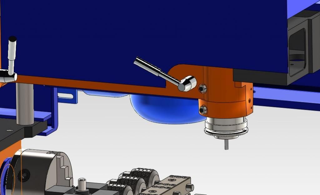
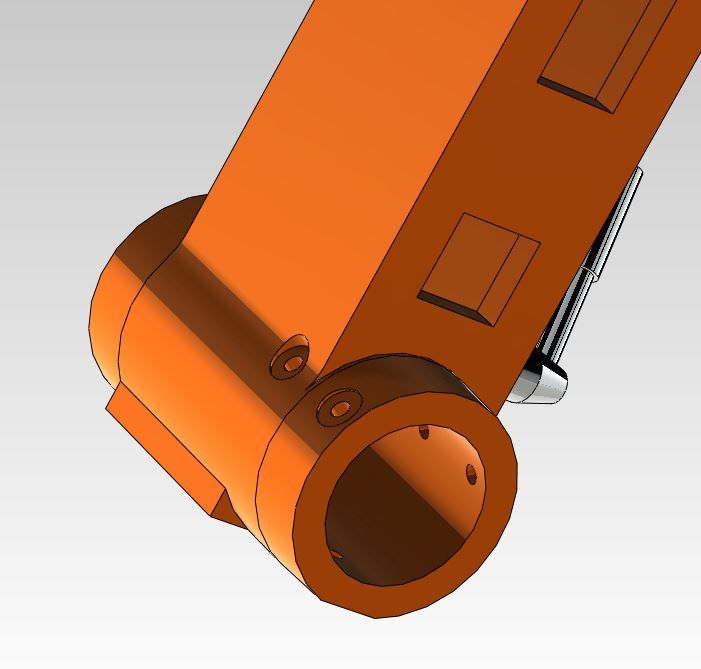
Here is a view with the casting on its own. You can see the holes to the left side of the casting so the grub screws will push the quill towards the right (and towards its right keyway). They work in the same direction as the Z axis clamp handle.
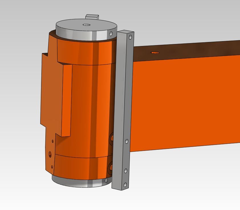
I made a simple jig to help me drill. Just two steel bars with holes drilled in them and plugs for either end of the quill. Obviously I’ve left out the bolts
I connected the parts together with in this sketch, but you get the idea. I could then drill the holes by hand.
Then I stripped the jig away and finished the holes with a counter bore drill.
This project was not entirely successful for a number of reasons.
Because the quill travel is pretty long the top edge of the quill drops a long way in the casting.
This means the top grub screw cannot be as far up as I would have liked (above the bottom one) otherwise it would be uncovered by the top of the quill passing it as it travels to its lowest extent.
Whilst they do have a beneficial effect, the quill still moves because of that belt load at the top of the quill pulling the quill to the rear left is difficult to offset right down at the other end of the quill.
I have seen several alternatives to this approach, such as cutting the lower end of the quill casting with a disc cutter then putting a big saddle around the bottom of the quill to close up the casting. Initially this seems great till you realise that the shape of the quill is not going to stay round and the bearing points will be point contacts.
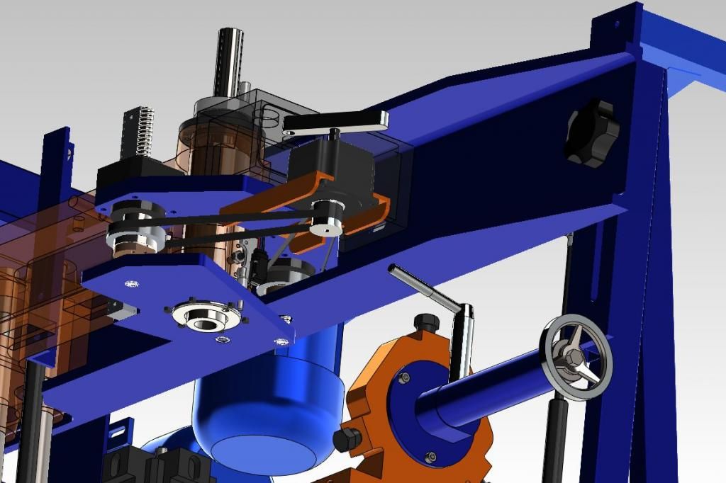
At present my “solution” is to put a bearing around that top pulley and put a bracket back to the casting. Perhaps I’ll use a gas strut- but the idea is to counter the belt tension forces and stabilize the very top of the quill. This then leaves the grub screws able to stabilize the bottom of the quill satisfactorily. Lastly, I want to put an extra Z axis ball screw (opposite to the first but on either side) so that the Z axis forces are on axis with the quill rather than offset.
Hopefully this shows the extra axis well enough for you to see what I mean.
It’s quite a bit of work, and I’m not really sure it is totally necessary, one of these upgrades on its own might be enough.
What I did notice jlm when I stripped the casting down was that the Z axis clamp bolt is not a good fit to the quill.
The clamping forces are concentrated on two points- I don’t think tightening it a bit when milling is entirely a good idea (I do it too so it’s not a criticism- I just want you to wince when you do it just like I do ;-).
I think if you are going to clamp while moving the Z axis an improvement to the clamp bolt is in order – perhaps a floating brass slipper to make a good “large area” contact that will both clamp when you bear down on it but also provide support when it is just nipped up a little- include in a nylon ring to the clamp nut and the whole thing can be prevented from working loose. One of the obvious things in this regard that I never thought about is to put a spacer under the clamping handle so that you can set where it starts to nip the assembly tight- set the handle so gravity keeps it tight rather than trying to undo it. Simple, but that works too.
One reflection I would end with. I have made several things using 3d machining and they are not rubbish. There are steps in them but I was able to buff them out. The machine is useable. This is an upgrade to make it better.
Someone must have some better ideas on here.
SMALL…. You’re the go-to guy when it comes to good ideas. What do you think?
This feels like a 100 watt problem and I’m a 60 watt kind a guy.
-
10-05-2014, 03:32 PM #11
Registered
- Join Date
- Jan 2008
- Posts
- 458
Re: Table mounted Chuck Gang for turning.
Guys,
I've had 3 Shoptask/Shopmaster machines- my first one was the old white 17-20 from 1994. That model had a saw cut in the casting with a couple ears for a pinch bolt, so to lock the quill you just tightened the handle and it squeezed the casting around the quill. By replacing the handle with a bolt, you could actually tighten up the clearance by carefully tightening the bolt to a point just before it clamped solid. On the new machines you can do a similar thing by replacing the handle with a stud and self locking nut for better control, and the nut won't work loose. However you need to remove the lock pieces and cut the arc with a boring head to match the diameter of the quill- this gives you a full contact around the quill.
Your belt tension should not be causing any quill rock, as the pulley rides on that ball bearing which is attached to the casting, and the belt tension should not be able to deflect the pulley and the spindle shaft- I would double check all that fit and the bearing first.
I think Julian's dual ball screw design will probably solve the whole thing by eliminating the one sided force on the quill. I would go with a larger ball screw- A 20 MM like the X, Y axes and also consider putting the ball nut up near the pulley where you could use a smaller pulley to get the ball screw in closer to the casting. You could maintain the same ratio by changing from 21-42 pulleys to an 18-36 set.
On a more extreme note, you can find linear bearing sets pretty cheap on e-bay, and if you found a set of 4 with 30 mm diameter shafts, you could replace the 4 lift bars with linear bearings and just use the mill head as your Z axis and use the quill for fine adjustments, then lock it down solid. I'm guessing that by changing the stock lift bars with linear bearings and the lift screw with a ball screw, you could achieve about the same max IPM with the mill head as you are getting with the quill.
-
10-05-2014, 05:41 PM #12
Member
- Join Date
- Oct 2009
- Posts
- 84
Re: Table mounted Chuck Gang for turning.
Thanks for the ideas and sorry for the hijack.
Back to the original thread. I'm ready to do something similar and will be watching to see how yours turns out.
-
10-05-2014, 06:18 PM #13
Registered
- Join Date
- Aug 2013
- Posts
- 55
Re: Table mounted Chuck Gang for turning.
Your belt tension should not be causing any quill rock, as the pulley rides on that ball bearing which is attached to the casting, and the belt tension should not be able to deflect the pulley and the spindle shaft- I would double check all that fit and the bearing first.
You are absolutely right Small, the belt tension should not affect it, this was a thoughtless thing for me to suggest.
I told you I'm a 60 watt bloke!.
I quite like the bridge idea though I notice I get some backlash on it- I probably need to choose a gas strut that is too strong or too weak as at present the friction at the tail end is clearly enough to create enough drag to make backlash. Also I use the bridge locked at one end to tram the mill. This would have to be shimmed out.
Otherwise I think it has lots of promise.
-
10-06-2014, 12:40 PM #14
Registered
- Join Date
- Jan 2008
- Posts
- 458
Re: Table mounted Chuck Gang for turning.
Julian,
I suggest you tram your head with all the locks loose. Also your grub screw idea could work on the mill head casting by putting the grub screws against the 4 columns to reduce any droop in the heavy mill head assembly if you want to stick with the original setup.
-
10-06-2014, 02:38 PM #15
Registered
- Join Date
- Aug 2013
- Posts
- 55
Re: Table mounted Chuck Gang for turning.
When I tram the mill I bring the bridge UP to the position I want, then I use the lock at the tailstock end to fix the bridge.
I then move the headstock end of the bridge up about 4mm- the lock prevents the tailstock end from moving.
This brings the set up very close to parallel- usually just a bit of adjustment and I'm on target.
Perhaps I should shim under the plate that mounts the bottom of the quadra-lift pillars so that it is pretty close to start with.
This preload may be as a result of the gas strut I have at the tailstock end, without it the tailstock end may have the 4mm of sag (I'll call it sag ...not droop! In the UK droop is a term for.... well, it means..... ummm.... its a slang word for...... uhhhh...... you'd take a little blue pill to stop it .....if you know what I mean) from gravity- putting it close to parallel.
My gas strut ....is like a little blue pill for the bridge. The bridge is too..... perky.
-
10-23-2014, 03:18 PM #16
Registered
- Join Date
- Aug 2013
- Posts
- 55
Re: Table mounted Chuck Gang for turning.
I made the mount bar from a chunk of 40mm x 40mm steel held in a vise.
I machined the T slot keyway along the bottom then the screw holes and their counter-bores, finally I put the chamfer cuts along the edges.
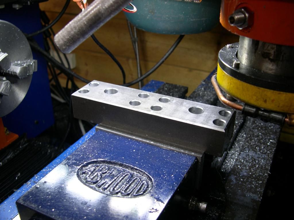
I finished off the first ops with a bit of jeweling of the surface to hold some protective oil and also to make it less easy to mark- or make marks less obvious.
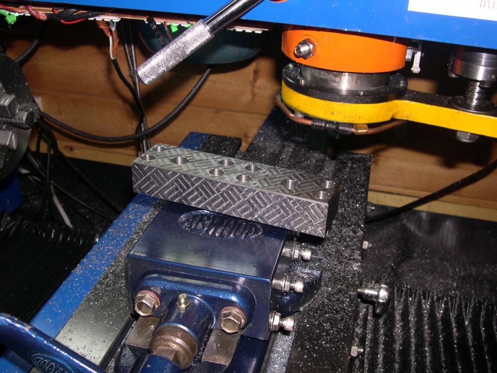
Next tasks are to make some T nuts, drill and ream the arbour holes then cut the pinch slots.
-
10-25-2014, 08:33 PM #17
Registered
- Join Date
- Aug 2013
- Posts
- 55
Re: Table mounted Chuck Gang for turning.
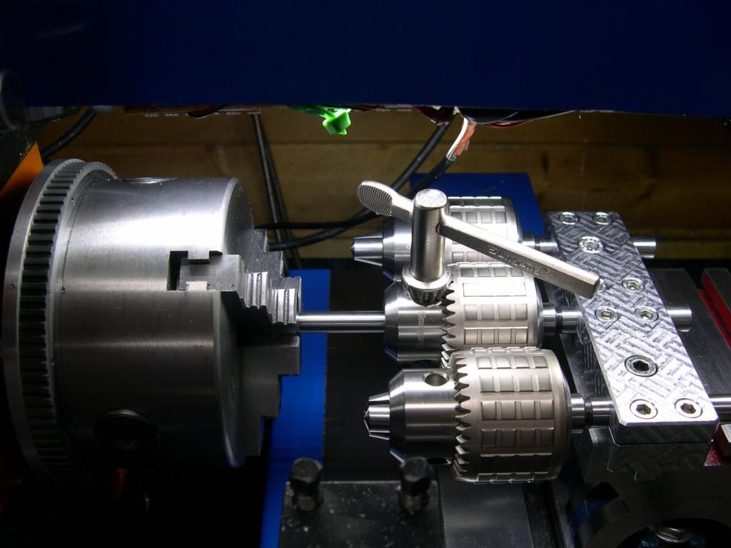
I simply bolted the assembly together and using a drill in the lathe chuck I drilled to 12.5mm then finally reamed to 12.7mm to take the chuck arbours.
For the end pinch slots I used a 75mm diameter slitting saw- however it was not so easy for the middle slots.
To cut the pinch slots either side of the middle hole required a little .....unconventional machining.
Here you see a hacksaw set between the chuck and the tailstock- I moved the table back and forth in the X and slowly cut the slots.
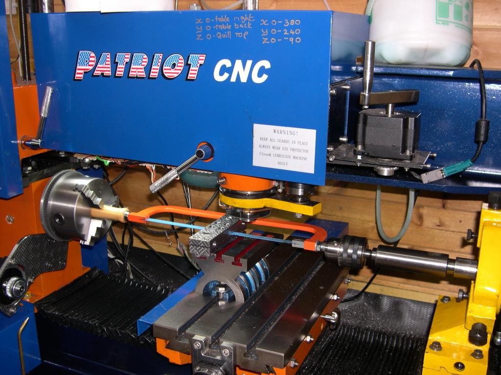
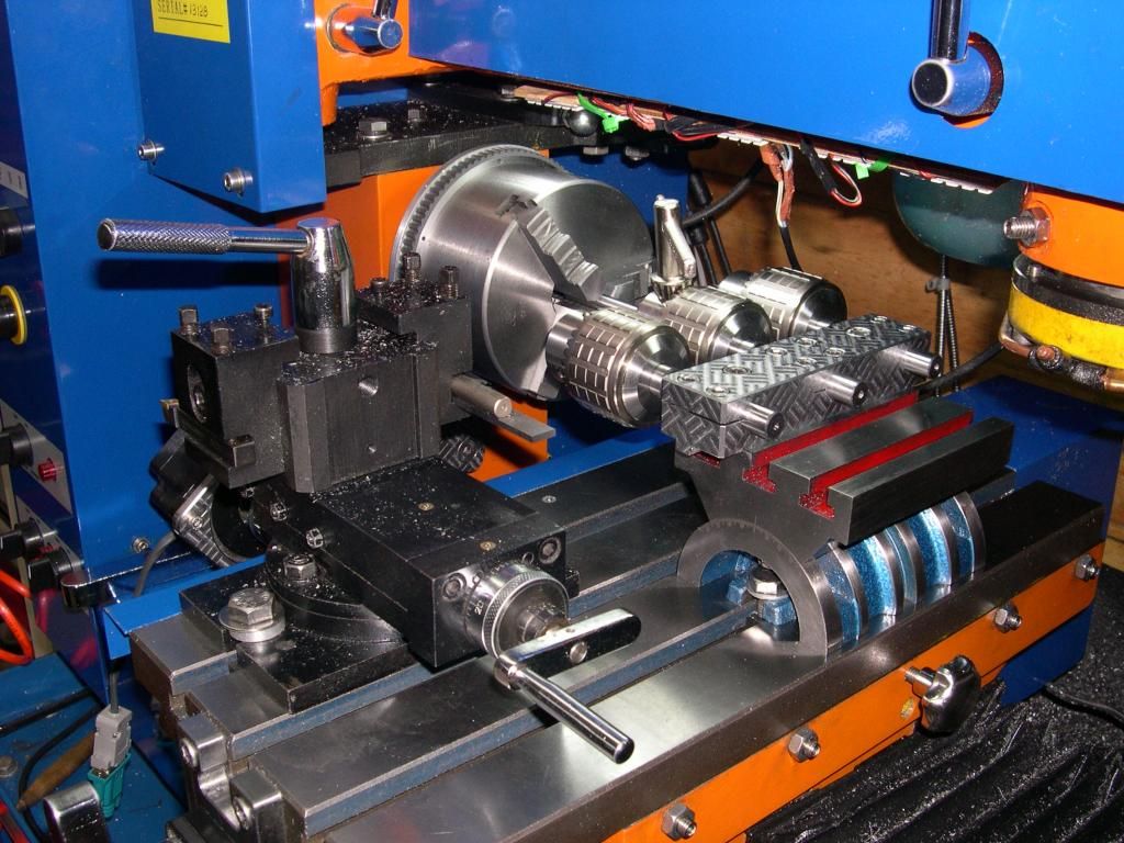
In the picture below you can see how I set the chuck gang into position on the bed: with a 10mm diameter drill blank in the lathe chuck, I wind it into the centre drill chuck then tighten it with a chuck key and that pulls the assembly square; finally I tighten the base bolts to hold it all in position.
Here is the finished chuck gang in place on the machine.
At last I can spot drill, drill and ream without changing the set-up.
-
10-26-2014, 11:45 PM #18
Member
- Join Date
- Oct 2009
- Posts
- 84
Re: Table mounted Chuck Gang for turning.
Nicely done, Julian. Looking forward to seeing the parts you are making with this setup.


 Reply With Quote


Similar Threads
-
Table mounted enclosure
By Beezle in forum Tormach Personal CNC MillReplies: 1Last Post: 10-09-2013, 04:13 PM -
Power Draw Bar and Table Mounted Rack Tool Changer?
By David Bord in forum Tormach Personal CNC MillReplies: 5Last Post: 08-12-2010, 03:16 PM -
success! big piece mounted and turning!
By pmurdock in forum Haas LathesReplies: 0Last Post: 08-25-2009, 12:46 AM -
Vertical mounted router table?
By 307startup in forum DIY CNC Router Table MachinesReplies: 15Last Post: 02-09-2007, 04:37 AM -
HF 8x12 MOD (Stud mounted chuck.)
By Dan S in forum Mini LatheReplies: 7Last Post: 04-18-2006, 06:16 PM
