


Credit for this link goes to slp_prlzys who posted it to General Electronics Discussion
This is posted to Open Source Controller boards as I hope it will be picked up and developed quickly
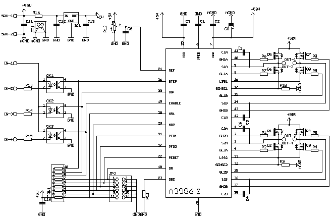
Allegro has a new Bipolar Stepper driver chip that drives N-FETs in a bridge configuration.
You can buy them now at Digikey for about $5.00
The chip includes high and low side drivers. - No IR interface chips required.
Look here
http://www.allegromicro.com/sf/3986/index.asp
A3986
Dual Full-Bridge MOSFET Driver with Microstepping Translator
Features
* 2-wire step and direction interface
* Dual full-bridge gate drive for N-channel MOSFETs
* Operation over 12 to 50 V supply voltage range
* Synchronous rectification
* Cross-conduction protection
* Adjustable mixed decay
* Integrated sinusoidal DAC current reference
* Fixed off-time PWM current control
Description
The A3986 is a dual full-bridge gate driver with integrated microstepping translator suitable for driving a wide range of higher power industrial bipolar 2-phase stepper motors (typically 30 to 500 W). Motor power is provided by external N-channel power MOSFETs at supply voltages from 12 to 50 V.
This device contains two sinusoidal DACs that generate the reference voltage for two separate fixed-off-time PWM current controllers. These provide current regulation for external power MOSFET full-bridges.
Motor stepping is controlled by the two-wire step and direction interface, providing complete microstepping control at full-, half-, quarter-, and sixteenth-step resolutions. The fixed-off time regulator has the ability to operate in slow-, mixed-, or fast-decay modes, which results in reduced audible motor noise, increased step accuracy, and reduced power dissipation.
The translator is the key to the easy implementation of this IC. Simply inputting one pulse on the STEP input drives the motor one step (full, half, quarter, or sixteenth depending on the microstep select input). There are no phase-sequence tables, high frequency control lines, or complex interfaces to program. This reduces the need for a complex microcontroller.
The above-supply voltage required for the high-side N-channel MOSFETs is provided by a bootstrap capacitor. Efficiency is enhanced by using synchronous rectification and the power FETs are protected from shoot-through by integrated crossover control and programmable dead time.
In addition to crossover current control, internal circuit protection provides thermal shutdown with hysteresis and undervoltage lockout. Special power-up sequencing is not required.
This component is supplied in an 38-pin TSSOP (package LD). The optional lead (Pb) free package (suffix –T) has 100% matte tin leadframe plating.
Results 1 to 20 of 826
-
09-18-2006, 01:59 AM #1
 Registered
- Join Date
- Mar 2004
- Posts
- 75
New Allegro Bipolar Stepper Driver A3986
-
10-01-2006, 12:06 AM #2
Registered
- Join Date
- Mar 2005
- Posts
- 2

This is a tough one!!! In a combination with IRF540 brings up to 10A at 50V which is quite enough power even for bigger steppers. Next week I will start prototyping my board. The only thing that is still missing is current limiter to approx. 25-30% when no step signal is detected.
Cheers
-
10-01-2006, 01:53 AM #3
Gold Member

- Join Date
- Jun 2003
- Posts
- 3312
This is the part I mentioned a earlier in the year I was going to wait for. I've been working a compatable design compatable with the other designs on my website for about 2 weeks. Have the 3986 parts in hand, those tssops are small. Most all smds. Cant see a non soldermasked board as buildable. Layout is a bear!
Phil, Still too many interests, too many projects, and not enough time!!!!!!!!
Vist my websites - http://pminmo.com & http://millpcbs.com
-
10-01-2006, 06:38 PM #4
Registered
- Join Date
- Mar 2004
- Posts
- 120
Nice chip, just finished a layout for the first prototype
with room left for a midband resonance compensation
circuit. My plan is to test the driver board separately
and switch in the compensation circuit afterward to save
on prototyping costs.
A hint for the curious... the compensation circuit consists
of a bandpass filter and a voltage controlled pwm 555.
more to follow,Garyembrace enthusiasm to accomplish the task
Gary Davies... www.durhamrobotics.com
-
10-02-2006, 07:06 PM #5
Registered
- Join Date
- Mar 2004
- Posts
- 75
Start of prototype board
Here is an update on a A3986 board
All components are regular thru hole except the A3986 TSSOP
I am gathering parts so my final may change depending on the parts I am able to buy
I use Target layout - I don't have eagle files
Any improvements or ideas appreciated.
FYI
Any other good ideas appreciated
-
10-02-2006, 08:20 PM #6
Registered
- Join Date
- Mar 2004
- Posts
- 120
with your placement of the fets... it will be
difficult to use heatsinks.
regardsembrace enthusiasm to accomplish the task
Gary Davies... www.durhamrobotics.com
-
10-02-2006, 09:20 PM #7
Registered
- Join Date
- Mar 2004
- Posts
- 75
I have a bag of clip-on heat sinks that slip on the TO220 chips Originally Posted by DR-Motion

The clip on heat sinks are very versatile.
I would like to use the back to back FET setup like Gecko but the prototype board was set up the way it is to use the simplest and most direct connection from the Allegro chip and the FETs.
After I get the chip up and running, refinements will follow.
Cheers
-
10-02-2006, 09:21 PM #8
Gold Member
- Join Date
- Jun 2003
- Posts
- 3312
Among others, your FET current paths and sense resistor arrangement is a problem.
Phil, Still too many interests, too many projects, and not enough time!!!!!!!!
Vist my websites - http://pminmo.com & http://millpcbs.com
-
10-02-2006, 09:37 PM #9
Registered
- Join Date
- Mar 2004
- Posts
- 75
Please explain your improvement ideas. Originally Posted by pminmo
I would like to fix it on paper before I commit it to the boardmaker.
Thanks
-
10-03-2006, 12:17 AM #10
Gold Member
- Join Date
- Jun 2003
- Posts
- 3312
You have to take into consideration high current paths and where to sense the voltage developed across the sense resistor. Same for grounds, motor supply, clamping........... low impedence signal drives, noise immunity.
Right now I need to finish mine, it's laid out, passes all my rules, just need to spend some time reviewing everything.Phil, Still too many interests, too many projects, and not enough time!!!!!!!!
Vist my websites - http://pminmo.com & http://millpcbs.com
-
10-04-2006, 09:07 PM #11
Registered
- Join Date
- Mar 2005
- Posts
- 2
@DR Motion.
Can you please explain the things about midband resonance compensation, I would be glad.
Cheers
-
10-06-2006, 12:43 PM #12
Registered

- Join Date
- Feb 2005
- Posts
- 130
Here explanation is... Originally Posted by Azrael
http://www.cnczone.com/forums/showpo...0&postcount=30
---
Here, starts of my projects
Add something else ?
-
10-06-2006, 01:35 PM #13
Registered
- Join Date
- Jun 2006
- Posts
- 7
Add something else ?[/QUOTE]
I think, diodes missing on h-bridge for each mosfet.
-
10-06-2006, 05:05 PM #14
Registered
- Join Date
- Feb 2005
- Posts
- 130
MOSFET have diode... Originally Posted by tmobile12345
and
A3986 have SR - synchronous rectification mode....
Originally Posted by allegro
-
10-06-2006, 08:58 PM #15
Registered
- Join Date
- Jun 2006
- Posts
- 7
Ok, You have right. Do you think use Irf540 or something else?
-
10-06-2006, 09:45 PM #16
Registered
- Join Date
- Mar 2005
- Posts
- 339
Do you have the board layout? Maybe in eagle format?
Thank you.
Zoltan
-
10-06-2006, 10:17 PM #17
Registered
- Join Date
- Feb 2005
- Posts
- 130
irf540 25A/80V Rds(on)=0.077R Qg(tot)=38-59nC Originally Posted by tmobile12345
irfz44n 49A/55V Rds(on)=0.0175R Qg(tot)=63nC
irfz24n 17A/55V Rds(on)=0.07R Qg(tot)=20nC
-->> IRFZ24N
I'm working on that... Originally Posted by zoltan
yes... Originally Posted by zoltan
-
10-07-2006, 08:29 AM #18
Registered
- Join Date
- Mar 2005
- Posts
- 339
Hi,
Thank you for reply. I am interested in it. Are you going to share it?
Thank you.
Zoltan
-
10-07-2006, 11:00 AM #19
Registered
- Join Date
- Feb 2005
- Posts
- 130
yes... I'm going... Originally Posted by zoltan
now, I'm going to make good layout of pcb...
-
10-07-2006, 12:23 PM #20
Registered
- Join Date
- Mar 2005
- Posts
- 339
OK. Thank you. I am waiting for your pcb.
Zoltan

 Reply With Quote
Similar Threads
-
Allegro stepper driver
By EUnit in forum Stepper Motors / DrivesReplies: 2Last Post: 01-05-2011, 06:29 PM -
A3985/A3986 5A/50V Bipolar Stepper Design
By NE5534 in forum Open Source Controller BoardsReplies: 10Last Post: 09-23-2010, 05:39 PM -
Allegro A3986...Stepper Translator
By slp_prlzys in forum CNC Machine Related ElectronicsReplies: 2Last Post: 06-07-2009, 07:59 PM -
Allegro A3986
By Kevint in forum Stepper Motors / DrivesReplies: 2Last Post: 12-07-2008, 07:53 PM
