


Well, I've been asking questions and gathering for awhile, and figure's it time to start the thread. I have a very sturdy and accurate 12" x 12" cnc table I'm going to convert to a laser head. I just received my 40watt sealed tube yesterday (in one piece :cheers: ) and the powersupply and lens will be here today or tomorrow. I have the two gold mirrors necessary also.
The lens I'm using has a 2.5 inch focal length, and is a GaAs lens. I was told that it was just as good as the ZnSe lens, and for the price I was willing to take the gamble. Plus, I can't seem to find too many ZnSe lenses on ebay right now.
I will post pictures tonight when I get home of the tube and setup, and show you what I'm going to do.
Also, a little background. I converted the CNC table to use a HF trim router, and it worked well. The repeatability is amazing, and there seems to be no perceptible backblash when using a dial indicator. I'll have each axis move back and forth numerous times and it will still return to zero. I love the bishopwisecarver bearings and rail setup it uses. I'm going to emulate this for my larger CNC router. But I started a scrapbooking business with a partner (female,or course) and she had a lot of ideas for products. Well as it turns out, most of it's made of 1/8" hard board, and then acrylic sheet. Also stamps. So I started doing them on the router, but it was very annoying. The accuracy and speed were more than acceptable, but the hold down situation was awful. I have to use a ton of double stick tape, and then it's so strong I'll always loose 10% of whatever is on the sheet. So after researching, I knew a laser would be the best bet. There's only one other scrapbooking supplier I've found that uses a laser table as well. Most of it is die cut, but then you're limited on what you can buy. If a sheet took 30 minutes of run time, it would take an additional 45 minutes of prep time, removal and clean up time. With the laser I'll simply have to place the sheet on, cut, and remove. So I'm pretty excited. Plus, lasers apparently do very well with acrylic, which is were the bigger profit is.
After I post some pictures, I'll have a few questions for you guys. And I certainly welcome any questions you might have for me! :rainfro:
Thread: New CNC laser log
Results 1 to 20 of 66
-
10-26-2006, 07:31 PM #1
 Registered
- Join Date
- Sep 2005
- Posts
- 249
 New CNC laser log
-
10-26-2006, 10:49 PM #2
Registered
- Join Date
- Jul 2005
- Posts
- 78
What is scrapbooking?
Have you considered a vacuum pump and a table full of holes to hold down the sheets?
Good luck with the conversion, looking forward to the pics
-
10-26-2006, 11:19 PM #3
Registered
- Join Date
- Sep 2005
- Posts
- 249
Scrapbooking is when you cut up pictures and paper and make an album out of them. Kind of like a keep sake thing. It's taken overcome women here on the west coast!
My wife is pretty big into it, and practically every other woman I know. I would love to do the vacuum setup, but the pieces I make are too small and intricate to hold up to the router. That would have solved a lot of my problems (financially!). I figured out the tooling costs, and with each letter it costs about $.06 for the router. The laser costs about $.0002 cents per letter in tooling. Pretty big difference. Although, I could have bought 65 routers for how much I paid for one Laser! But the real savings is the time. This will be so much more faster and less hassle. Plus, the CAM will be much simpler. No more having to worry about tool comp, or picking the inside or outside of a curve. I will have to edit a post for MC9 to spit out the g-code I need. I'm still looking into that. But for what I want to do, I might just end up buying SheetCam. Don't need anything real fancy, simple 2D will work. I'm really anxious to get home, knowing all my packages have arrived! I'm certainly going to do a comprehensive list of materials, and all the factors required to cut them. I think there's too much mystery out there with that. But I suppose it's because there's a lot of factors that determine cut quality and speed.
-
10-26-2006, 11:32 PM #4
Registered
- Join Date
- Jul 2005
- Posts
- 78
Ah, that makes sense on the sticking down then... I'm still confused why you need a laser cnc machine to make a scrapbook... do you make up custom books for people or something? Sounds like a great idea though, if you are able to make it work.
-
10-27-2006, 01:41 AM #5
Registered
- Join Date
- Sep 2005
- Posts
- 249
OK, pictures as promised!
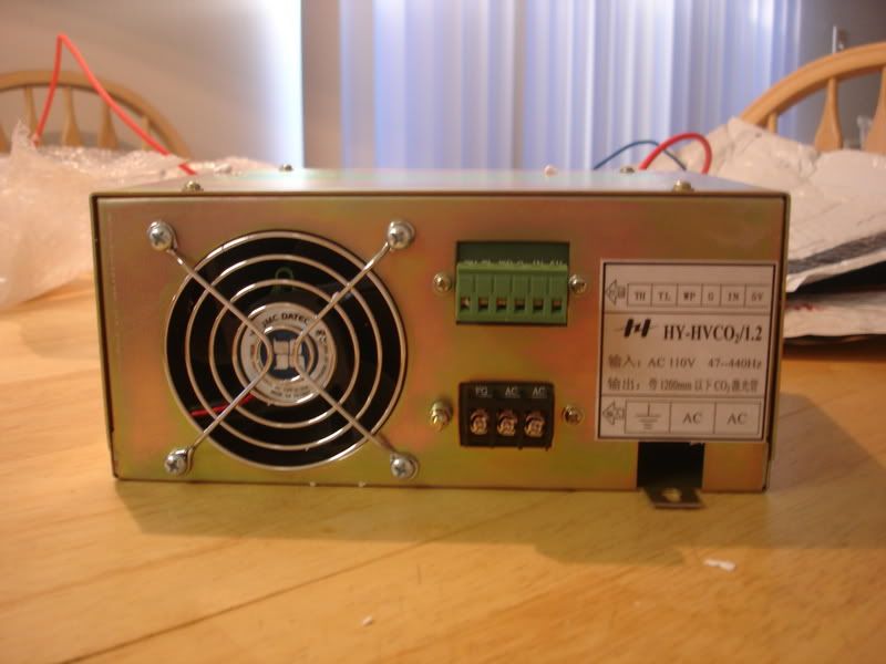
This is the power supply. Luckly no parts were jingling around. Seems to be in one piece!
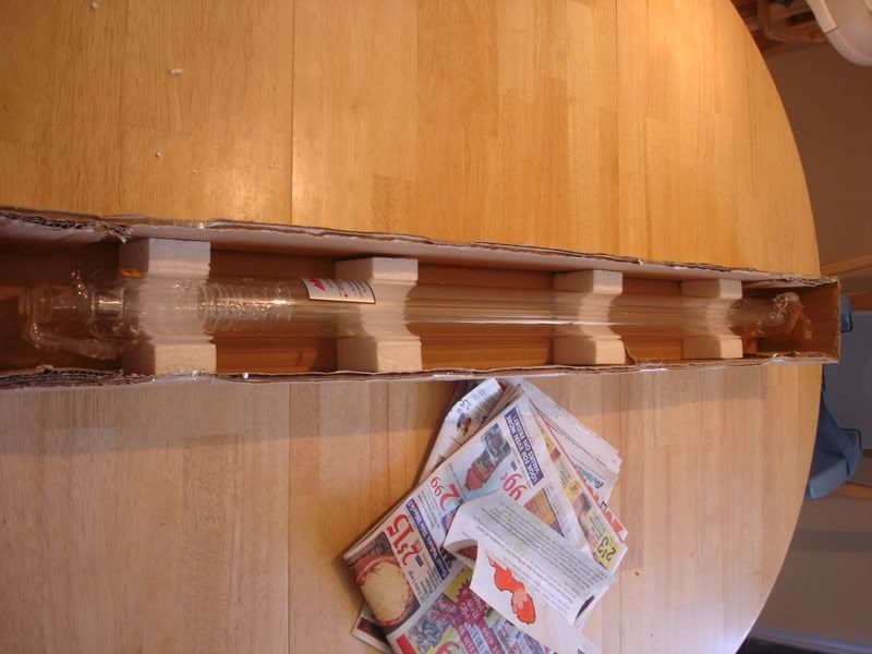
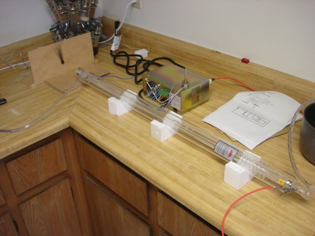
This is the 40watt laser tube. It's about 40 inches long, and 2 inches in diameter. I thought the majority of the tube was the water jacket, but it seems it just an outside layer of the actual laser tube. I can see now why you would need a higher flow pump.
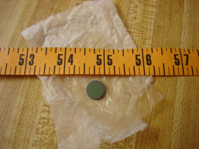
This is the lens I bought with it. I'm kind of disappointed, but if anyone can comment to the effectiveness of these lenses, I would appreciate it. I'm still in the market for a ZnSe lens, but well see how this one does with tests. It's 1/2" in diameter, so I'm a little worried about it taking in the whole beam from the laser. But I'm sure it will do for now.
And lastly, this is the CNC I'll be hooking it up to. I'll be taking the router and whole z-axis assembly off, but not before I machine some stuff I need to hold the laser and what not. I'm running a xylotex board, with 279 oz motors. I can drive it up to 600 in/min, but I keep it at 300 in/min rapids. I need to make a bearing setup for the top leadscrew, otherwise it can whip and bind sometimes. I obviously won't be cutting that fast, so I'm happy with the lower speeds. Also, the accuray and most importantly repeatability is way more than expected. It hasn't missed a beat yet. Also, the 279 oz are plenty powerful. I can't even stop the table when it's moving around. A lot more power than I expected! I can see how people drive the larger MDF cnc's with this setup.
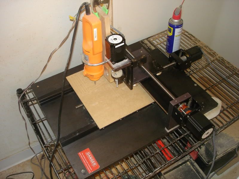
I'll be shooting the laser beam down the what I call x axis. So the laser will be perpindicular to the machine. I'll have one mirror at 45 degrees to shoot the laser down the z and through the lens. Pretty simple. I'm going to make it adjustable, but it shouldn't be near as bad as some other setups. Of course, this machine is temporary. It's just to get the business going and taking off. I'm immediately building a larger CNC router, and a larger CNC laser table.
I'll be kicking it on and taking pictures and movies tonight! So I should have pictures in the morning. Plus a status on what materials I'm cutting, how much power it takes, and how fast they cut. I'm pretty excited!! (Oh, and wish me luck. Although I'm very careful around equipment, my wife is really worried I'll blind myself. But I have goggles and shields to protect me.)
-
10-27-2006, 01:49 AM #6
Registered
- Join Date
- Jul 2005
- Posts
- 78
Great, thanks for the pics
How are you going to align the laser and the mirrors accurately enough?
Are all the axes stiff enough that the end of the laser won't wander after being reflected round the intermediate parts of the machine?
Have you got some front-surface mirrors?
Good luck!
-
10-27-2006, 03:23 AM #7
Registered
- Join Date
- Sep 2005
- Posts
- 249
Yes, I believe the axis are sufficiently rigid. They are actually very ridgid, but I won't say it'll work perfectly until I try.
You never know I suppose. As far as alignment, I'm going to atempt alighing a little red laser with the beam. Mostly just burn a hole, see if it's acceptable, and then have it burn a origin and boundaries. I know there's a lot more than can go into aligning but I only have one mirror to adjust, so I'm thinking it won't be that hard. I have a big mill to make some of the parts I want for the laser. I'm just looking to get it basically cutting, not optimized.
I need to rig up a couple DC relays to control the pump and air assist selonoid. I'm at school right now, and don't get out until 10 pm, so it'll be a loooong night. I mostly want to make sure I can get the laser working, and completely verify that nothing is busted. But I hope to have it up and cutting by the middle of next week. That's pretty ambitious though, so it'll probably be done by next Saturday. With all the orders we're getting, it needs to be done yesterday.
-
10-28-2006, 10:27 PM #8
Registered
- Join Date
- Sep 2005
- Posts
- 249
I NEED HELP! This power supply is a bit trickier than I expected. The laser tube is wired up (nothing to brag about
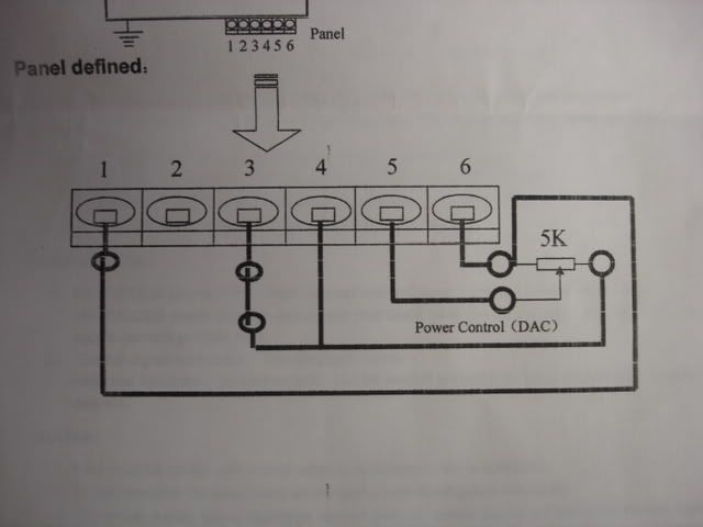
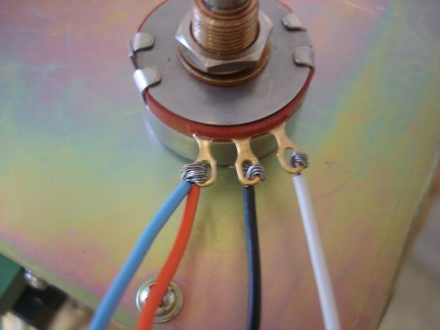
) but the power supply won't put power to the laser unless I use the TTL or CMOS or potentiometer. I've attatched some pictures on what I have so far, and would REALLY like some opinions. The directions are not very good, escpecially for someone like me. Again, I would REALLY like someone's opinion on what I need to do!
-
10-28-2006, 11:28 PM #9
Gold Member
- Join Date
- Oct 2004
- Posts
- 742
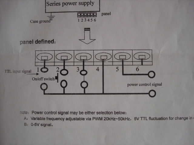
So far, every connection that has been made to the potentiometer is correct per the wiring diagram on the power supply.
The white wire should connect to both terminals 3 and 4 (WP and G) per the wiring diagram. At present it is only connected to pin 4. (G)
The low voltage side of the potentiomenter will be the side with the white wire and voltage should increase as the pot is turned towards the Red & blue wires on the pot. (In other words, the pot will work in reverse as viewed from the knob end.
Jerry
-
10-28-2006, 11:30 PM #10
Registered
- Join Date
- Sep 2005
- Posts
- 249
Thanks! Thanks! Thanks!
-
10-29-2006, 06:48 AM #11
Registered
- Join Date
- Sep 2005
- Posts
- 249
YEEEES! I have it up and running on its own. Sure enough, I just had to connect the other wire, and I could control it with the pot. Without the focus lens, the beam was about .14" at 4". Definetly creates a lot of smoke. Then with the focus lens, roughly 2.5" away, the dot size was about .01". These are rough measurements. It was crazy seeing the little dot of white light. I had to keep whatever was in front of it moving though, because it would burn through very quickly and start creating a lot of smoke. Speeds and feeds are VERY important I can already see. I am seriously impressed with how fast I can cut through things. I've already tested my 1/8" hardboard, cardstock and a thick cotton/poly cloth. It did absolutely marvelous on each one. I haven't even turned the power up half way. It barely needs to click on and it's cutting through. Definetly happy with the 40 watts! Also, I practiced with some acrylic. VERY small kerf, and left a glass edge. I can see why that is a popular thing to laser cut! Although, the stuff I was using definetly smells, but it's nice there's no smoke. Definetly going to setup a serious blower and filter for it. I'm just so excited right now!! My mind is racing with all the possibilities! I will definetly have pictures and hopefully proper sized video's soon. I need to work immediately now to get it setup on the CNC, but that won't be the hard part. Thanks again everyone for the suggestions and answers!
-
10-29-2006, 03:05 PM #12
Gold Member
- Join Date
- Oct 2004
- Posts
- 742
If you want to remotely control the laser tube via the software or breakout board, you can break the white wire between terminals WP and G and install an Off/On switch, a laser tube Emergency Stop Cutoff , or a set of relay contacts controlled from software, or other configuration. Originally Posted by WilliamD

I believe that is what the two circles indicate in the WP line.
Congratulations!
Will be looking forward to more posts.
Jerry
-
10-29-2006, 06:05 PM #13
Registered
- Join Date
- Nov 2005
- Posts
- 35
why dont you have the ground in on the ground post also we have our on it we have the same one if it works it works we were told we hade to put it on so we did
-
10-29-2006, 08:19 PM #14
Registered
- Join Date
- Jul 2005
- Posts
- 78
Great work William!
Glad to see it starting to work... is it a CO2 laser? So it is infrared? How do you measure the size of the dot, or are you going by how big a hole it burns?
-
10-29-2006, 08:49 PM #15
Registered
- Join Date
- Sep 2005
- Posts
- 249
Mat-C
Thanks! Yes, it is a CO2 laser. And yes, I can only measure the size of the dot by the hole it burns. It would cut through some 1/8" hardboard at .01", but that's not with it setup properly. Who knows if I had it at it's optimal focual point.
CJL5585 and waldo2413
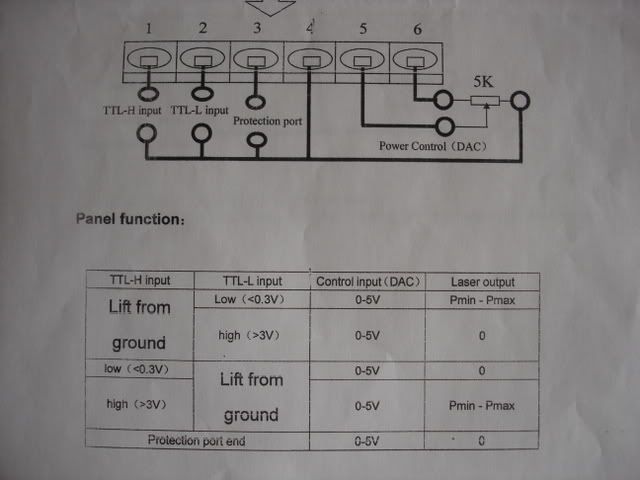
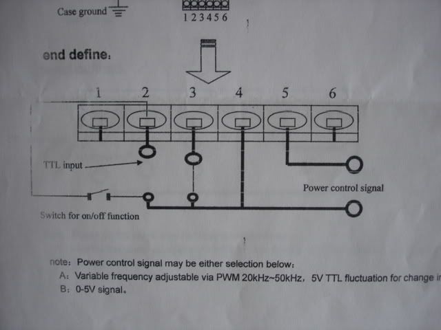
Sorry for all the questions, but I'm trying to figure out how to wire it to be controlled by the computer. I'm uploading some more images. It looks like they give a few examples, but I'm not as affluent as I'd like, yet. I want to control it by on/off 5V signals. I believe that is the TTL portion, although I don't get the high and low part. I'm using Mach3, and figuring out how to control a spindle in there with M3 and M5 codes.
Here are some shots of the setup right now. It's setup on my kichen counter!
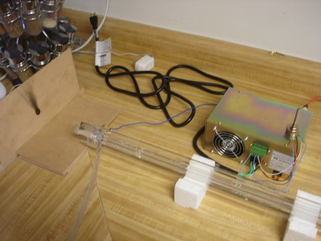
Again, any and all help is greatly appreciated! I'm working on the mechanics of getting it hooked up to the CNC, and if I can figure out this wiring issue, I can probably have it up and running by the end of today!
-
10-29-2006, 09:11 PM #16
Registered
- Join Date
- Jul 2005
- Posts
- 78
Wow, they explain all that stuff badly... or translate it badly.
My guess (sadly that is all it is) from all the diagrams:
"lift from ground" means "disconnect".
So you can use either active-high or active-low into ttl-h or ttl-l, and just disconnect the other one. Here is what you connect to your parallel port if feeling brave.
Pin6: +voltage out.
Pin5: power level input, 0-5v DC (eg from pot as you tried), or 5v PWM signal 20KHz-50KHz (later, when want a nice accurate power level...)
Pin4: ground
Pin3: protection... connect to ground to power up. (eg for case or big on/off switch).
Pin2: Low for on (or disconnect if using pin 1)
Pin1: High for on (or disconnect if using pin 2)
-
10-29-2006, 10:24 PM #17
Registered
- Join Date
- Sep 2005
- Posts
- 249
So, if I understand correctly, I have the wire coming from the breakout board for the PWM signal from Mach going to pin5. Then I'm going to connect WP and G, pin3 and 4. Then I'm going to connect either Pin1 or 2, to pin6? I'm going to try that. I know that the PWM signal from mach comes from the step pin on the Spindle setup. I have that wired up and set accordingly.
-
10-29-2006, 10:34 PM #18
Registered
- Join Date
- Jul 2005
- Posts
- 78
As I understand it, my continued guesses are:
Pin5 to mach3 PWM: yes, but I don't know about the spindle stuff.
Pin3 to pin4 yes.
If you are using Pin5 to switch on and off, then yes you would connect Pin2 to Pin4 (ground). (Pin1 to Pin6 would do too).
If activating under comp control I strongly suggest you have a big on/off switch, complete with big red flashing LED to indicate "laser is on or could start at any time".
I'm reminded of the warning notice on the physics laser lab door: "Do not stare into beam with remaining eye".
Good luck
-
10-29-2006, 10:42 PM #19
Registered
- Join Date
- Sep 2005
- Posts
- 249
OK, I tried that, and the laser comes on, but doesn't react to anything I do on the computer. I think I'm beginning to understand more how they want it setup. Still very confusing though.
I have to go get my voltmeter to verify that Mach is doing it's job, and then will continue from there. Thanks a lot man! I'm still planning on having it running by tonight.
-
10-30-2006, 01:12 AM #20
Registered
- Join Date
- Nov 2005
- Posts
- 35
pin one oe pin 2 is for the way ttl how it on the break out board some send it iy in high some send it in low on the link motion aka solustan board that we have it was in low if my mind is right we used them it cost a lot but we can send it out in coral draw or any printer style and we can do gray scale i hope it help my typeing and english is bad

 Reply With Quote