


Hello people,
new here but with a major (programming?) problem.
I'm trying to manufacture a ball joint on my Okuma Genos L300EM. Roughing an finishing cycle is done with a round tool, dia. 4mm (R=2).
So, when trying to finish the ball shape, the ball will become shiny oat the front side and will remain unmachined at the back side.
Settings: nose comp x=2, z=0, P8 and G42 for programming with a neutral round shaped tool.
I have tried G41, P3, P2, and changing the settings multiple times. The back side of the ball is not being finished whatever I've tried.
Please post your comments
Results 1 to 7 of 7
-
04-08-2015, 05:41 PM #1
 Junior Member
- Join Date
- Apr 2015
- Posts
- 3
Help with round tool - nose compensation
-
04-08-2015, 10:30 PM #2
Gold Member
- Join Date
- Aug 2011
- Posts
- 2517
Re: Help with round tool - nose compensation
the problem isnt your tool nose comp, its more likely your roughing cycle. you probably put some U and W finishing allowance on there. you cant use a cycle to rough a ball because the W+ will cause the tool to cut into the back of the ball. you need to program it using CAM software, or use some other method like a couple of cycles, or use W0 and a larger U+ to leave some material for finishing. Or rough the front of the ball in a cycle and use your round tool as a grooving tool to rough the back of the ball leaving some material on the back of the ball.
There are several ways to solve the issue.
Post your program here and we can see whats going on and fix it.
-
04-09-2015, 02:29 AM #3
Member
- Join Date
- Apr 2015
- Posts
- 31
Re: Help with round tool - nose compensation
fordav is correct. i have run into this before and i personally go with the w0.0 and bigger u finish amount myself but a plunge turn cycle on mastercam will give you the best options.
-
04-09-2015, 08:56 AM #4
Gold Member
- Join Date
- Aug 2011
- Posts
- 2517
Re: Help with round tool - nose compensation
It can be done with 2 cycles (using U and W)
first cycle cuts the front of the ball and the OD straight using U+ and W+
2nd cycle cuts backwards (from rear to front) with U+ and W- (or plunge a groove at the back then use a facing cycle with W-)
Ideally use CAM software then you don't have to worry out anything.
The end result will be something like the pic attached.
there is another way but you have to cheat by faking the profile of the ball.
instead of a full ball radius, program the roughing to machine the front of the ball up to the largest diameter (top OD of ball) then go back in Z- some amount (~1mm) then program the back of the ball (all of it is done in just one cycle). you'll end up with a flat on top of the ball AND some meat on the back of the ball. with a large enough flat you can even use U+ and W+. Say make the flat -1mm and the W+0.5 and you will have 0.5mm on the back face of the ball.
after it is roughed, program the correct profile long-hand and machine it to the real size.
problem solved without CAM software
as I said above there are several ways to solve this issue ;-)
-
04-11-2015, 04:05 PM #5
Junior Member
- Join Date
- Apr 2015
- Posts
- 3
Hey people,
first of all let me thank you for the instan replies.
And yes, W0.0 and U++ helped me finishing the part.
Initial settings: blah blah W0.1 U0.1 (stainless steel)
Correct settings : blah blah w0.0 U0.3
I also tried 2 separate routines for roughing and finishing the back side but nothing changed (at least at the graphics)
If you want, I can upload the code for roughing and finishing. For more complicated geometries I use IGF. I don't have other CAM software at the moment
Here are some pictures before and after applying the new settings
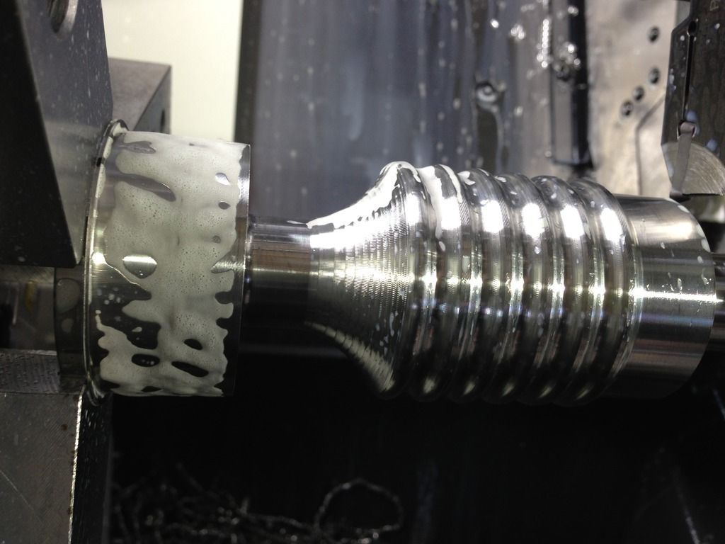
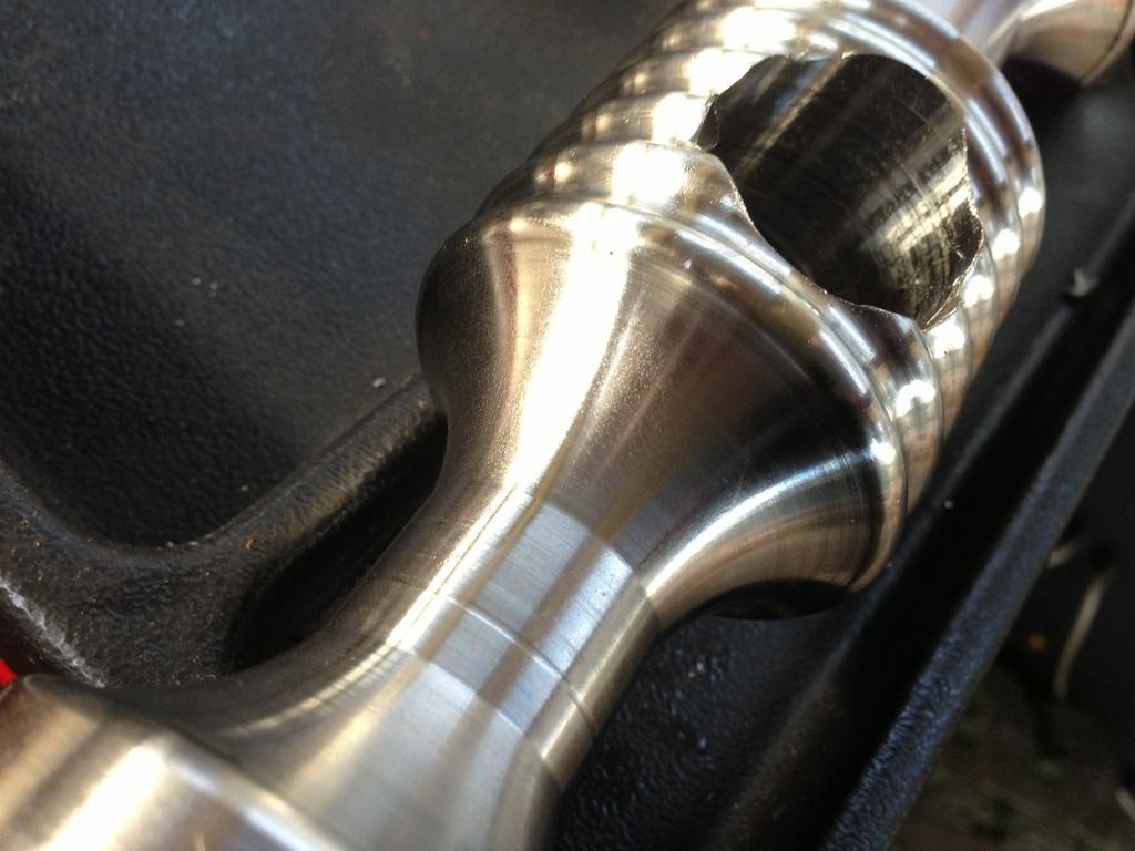
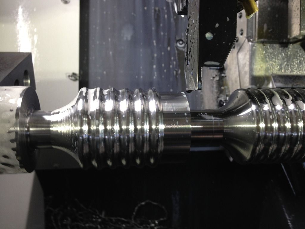
Again thanks a lot. Now I've found this forum I'll try to be an active member of this community
-
04-12-2015, 03:24 AM #6
Gold Member
- Join Date
- Aug 2011
- Posts
- 2517
Re: Help with round tool - nose compensation
since you have IGF why didn't you just program the entire part using it to avoid that problem?
if you upload the code it could be fixed but it would be easier to program it properly using the drawing.
if you dont want the drawing public send me a PM.
if not, then we are done, you have your parts so nothing more to be done.
-
04-12-2015, 11:08 PM #7
Junior Member
- Join Date
- Apr 2015
- Posts
- 3
Since I failed writing the code myself, I used IGF for it. I would use it anyway since the part has some Y axis milling.
Now for the part... it is a curtain hanger for my new home, not a big deal. And sorry, it is not a ball joint as I wrote above. I did it to give you a clue for the geometry.
I have programmed a ball on the CNC without any problems. It was first point X0Z0, G03 X50 Z-25 R25 and then the second roughing routine was X50 Z-25 and then G03 X35 Z-... R25. (PS: I use 2 roughing cycles because the Okuma control thinks it's better to make the part thinner near the chuck first rather than the tailstock side)
For the ball geometry we have two G03s one after the other. For the curtain hanger we have G03 followed by a G02 and here is the problem. Of course, all G02s remained unmachined after finishing cycle with W+
Food for thought, here is the code (roughing and finishing cycle) for the first half of the part:
NAT03
N0200 G97 S568 (M08)
N0201 T030303
G00 X56 Z0.46
M08
N0202 G96 S100
N0203 G85 N0204 D2 F0.18 U0.1 W0.1
N0204 G81
N0205 G00 X50.03
N0206 G01 Z-3.54 G42 E0.18
N0207 G03 X53.02 Z-8.73 I-0.508 K-2.957
N0208 G02 X53.02 Z-13.18 I2.013 K-2.225
N0209 G03 X53.02 Z-17.64 I-2.007 K-2.23
N0210 G02 X53.02 Z-22.1 I2.007 K-2.23
N0211 G03 X53.02 Z-26.56 I-2.007 K-2.23
N0212 G02 X53.02 Z-31.02 I2.007 K-2.23
N0213 G03 X53.02 Z-35.47 I-2.013 K-2.225
N0214 G02 X53.02 Z-39.93 I2.007 K-2.23
N0215 G03 X53.02 Z-44.39 I-2.007 K-2.23
N0216 G02 X53.02 Z-48.85 I2.007 K-2.23
N0217 G03 X50 Z-54.03 I-2.015 K-2.223
N0218 G02 X25 Z-68.82 I11.354 K-22.273
N0219 G01 Z-95
G01 X51
N0220 G40
N0221 G80
N0222 G97 S707 (M09)
NAT03
N0300 G97 S707 (M08)
N0301 G00 X54.03 Z-1.54 T030303
N0302 G96 S120
N0303 G87 N0304
N0304 G81
N0305 G00 X50.03
N0306 G01 Z-3.54 G42 F0.18
N0307 G03 X53.02 Z-8.73 I-0.508 K-2.957 F0.08
N0308 G02 X53.02 Z-13.18 I2.013 K-2.225
N0309 G03 X53.02 Z-17.64 I-2.007 K-2.23
N0310 G02 X53.02 Z-22.1 I2.007 K-2.23
N0311 G03 X53.02 Z-26.56 I-2.007 K-2.23
N0312 G02 X53.02 Z-31.02 I2.007 K-2.23
N0313 G03 X53.02 Z-35.47 I-2.013 K-2.225
N0314 G02 X53.02 Z-39.93 I2.007 K-2.23
N0315 G03 X53.02 Z-44.39 I-2.007 K-2.23
N0316 G02 X53.02 Z-48.85 I2.007 K-2.23
N0317 G03 X50 Z-54.03 I-2.015 K-2.223
N0318 G02 X25 Z-68.82 I11.354 K-22.273
N0319 G01 Z-95
G01 X51
N0320 G40 55 Z-93
N0321 G80
N0322 G00 X56 Z-90
N0323 G97 S568 (M09)

 Reply With Quote


