


Hey everyone
Ive been working on this for a while but never got around to posting it. My intention was to build it rigid enough to machine stainless etc so its ended up being rather substantial for its size.
This is more or less where it stands now, Ive just dropped it off for stress relieving today.
Cheers
Jonathan
Results 1 to 20 of 272
-
05-20-2015, 03:10 AM #1
 Registered
- Join Date
- Jan 2011
- Posts
- 80
 Solid Bench Top Mill Build (warning large photos)
-
05-20-2015, 03:56 AM #2
Registered
- Join Date
- Jun 2012
- Posts
- 17
Re: Solid Bench Top Mill Build (warning large photos)
You are an artist.
What kind of travels will it have?
-
05-20-2015, 04:21 AM #3
Registered
- Join Date
- Jan 2011
- Posts
- 80
Re: Solid Bench Top Mill Build (warning large photos)
Thanks I wish that were true but I appreciate it considering I just finished my apprenticeship. Originally Posted by cuttingchips

300x300x160mm I can change the Z axis if i need more travel. It was a pig of a thing to get a final design because I wanted to make it versatile as possible.
For example I can use Nema 23 or 34 steppers, I can add belt drive reduction if its necessary, I have made enough room to add a second ball nut to each axis to remove backlash, I can make spacers to lift up the X and Z assembly if I need more Z hight etc
The list goes on, Im even trying to work out an ATC and spindle for it but Im getting ahead of myself
-
05-20-2015, 06:09 AM #4
Registered
- Join Date
- Aug 2011
- Posts
- 21
Re: Solid Bench Top Mill Build (warning large photos)
excellent work :cheers:
-
05-20-2015, 10:33 AM #5
Registered
- Join Date
- Mar 2009
- Posts
- 39
Re: Solid Bench Top Mill Build (warning large photos)
Looks impressive. Didnt think you would be able to find anyone here in NZ to stress relieve at a reasonable price.What will the stress relieving involve? What size rails do you plan on using?
-
05-20-2015, 11:55 AM #6
Registered

- Join Date
- Apr 2006
- Posts
- 169
Re: Solid Bench Top Mill Build (warning large photos)
:cheers:
-
05-20-2015, 08:54 PM #7
Registered
- Join Date
- Jul 2011
- Posts
- 11
Re: Solid Bench Top Mill Build (warning large photos)
I made a similar mill. It works great. Cuts steel nicely. My biggest problem has been finding a suitable spindle. The Chinese 800W ones seem perfect but the bearings don't last long at all machining steel. I am worried that even an expensive spindle will have the same issue. What are your plans
-
05-20-2015, 11:08 PM #8
Registered
- Join Date
- Jan 2011
- Posts
- 80
Haha I pass heat treatments on the way to work. They quoted $70 of our toy money but the base weights 45kg hence the cost. As far as I know they just whack it in a furnace over night then bring it down to room temp. Originally Posted by shedbob
Ive got 15mm hiwin rails all round which including the ball screws cost a grand. Thankfully customs didnt tax me on them lol
-
05-20-2015, 11:13 PM #9
Registered
- Join Date
- Jan 2011
- Posts
- 80
Got any pics? I'd love to see it. Thats what worries me atm. I haven't settled on anything yet but im looking at getting the spindle from an x2 and powering it with an rc brushless motor. Im open to suggestions if you have a better idea Originally Posted by Dubbie99
-
05-25-2015, 08:32 AM #10
Registered
- Join Date
- Jan 2011
- Posts
- 80
Re: Solid Bench Top Mill Build (warning large photos)
Got the base back from stress relieving. Should hopefully start machining on it this week.
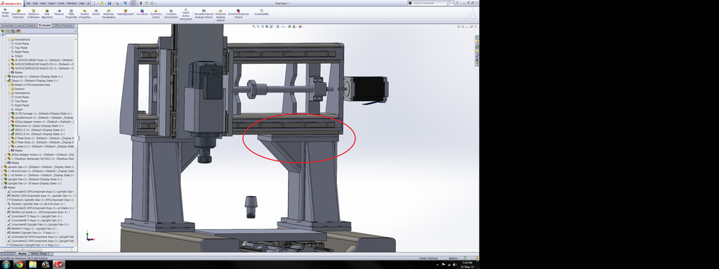
Im after a little design advice. As In the screenshot above I had planned to have the X axis welded to the uprights so it would be one unit. This is my preferred option but Im starting to wonder if I should bolt the X axis to the uprights to give more room for adjustment. This will add a lot more work so Im hoping its not necessary. The issue Im having with my initial plan is that it will be hard to line everything up for welding and after welding the uprights may bend inwards due to weld stresses.
Any thoughts?
-
05-25-2015, 12:42 PM #11
Registered
- Join Date
- Dec 2014
- Posts
- 37
Re: Solid Bench Top Mill Build (warning large photos)
In a fabricated machine you can never have too much adjustment or extra material to be machined back.
-
05-25-2015, 01:50 PM #12
Gold Member
- Join Date
- Jul 2007
- Posts
- 1602
Re: Solid Bench Top Mill Build (warning large photos)
Your base looks great. Are you planning to do any kind of fill to improve damping?
I think bolting is the way to go. I would suggest a bolt and grout approach where you have adjuster bolts coming through one flange and bearing on the other in addtion to the clamping bolts. You level/align with the adjusters and snug the clamping bolts. Before the final tightening, inject some metal filled epoxy or Moglice to fill the gaps and allow it to cure. If you want to be able to disassemble and re-assemble, apply release agent to one of the sides. As well you could install a few taper pins to help you get everything ligned up again.
bob
-
05-25-2015, 10:03 PM #13
Registered
- Join Date
- Jan 2011
- Posts
- 80
The thing is I have heaps of material to machine. I agree but do you think I can get away without the second bolting face? I figured once I had everything machined I would just shim it into square for final adjustment if needed Originally Posted by gary_808
-
05-26-2015, 03:52 AM #14
Member
- Join Date
- Sep 2006
- Posts
- 6463
Re: Solid Bench Top Mill Build (warning large photos)
Wow.....now that build is a beast.......and to mill a work area of 300 X 300.
I'm currently working on a steel tube build, also all welded, work area of 300 X 250 X125 mainly to mill steel etc
I decided to have the build in just two components......base and column bridge.
The column and bridge are all in one piece.
This enable the base section to be milled in one plane and the bridge and column section to be milled as a separate bolt on piece.
This is due to the fact that the linear rail base mounts pass under the bridge and so makes it impossible to mill and drill them in one hit with all the other milled faces..
At the same time, if the whole assembly is in one piece the bridge face needs to be machines at right angles to the base and so becomes a nightmare to set up and machine.
Having the base as a separate piece enables all the milling and drilling for linear rails, ball screw mounting pads and column mounting pads to be done in the horizontal plane in one hit without moving it, and so ensures they'll all be in line.
The bridge and column assembly can then be milled lying on it's back with the last operation to mill and drill the bottoms of the columns being done with the bridge/column assembly held vertically against an angle plate, but I might opt to turn the mill head sideways and do the milling on the base in that way without moving the column from the machine table.
I'll be welding the whole lot with a plasma welder and will not be stress relieving at all.
Welding with plasma is similar to a Tig welder on steroids, and the method of cold welding where the body is kept cool as you proceed ensures that expansion and contraction stresses do not get locked in to distort the assembly when machining occurs......BTDT etc.
I'll be watching this thread closely as it's close to what I'm doing.........sourcing the spindle will be the next head ache.
Ian.
-
05-26-2015, 04:16 AM #15
Gold Member


- Join Date
- Feb 2007
- Posts
- 4553
Re: Solid Bench Top Mill Build (warning large photos)
Very Nice Job!
Patience and perseverance have a magical effect before which difficulties disappear and obstacles vanish.
-
05-26-2015, 06:26 AM #16
Registered
- Join Date
- Jan 2011
- Posts
- 80
Re: Solid Bench Top Mill Build (warning large photos)
Thanks. Yea I designed it with the ability to fill with sand or lead shot etc if it needs it. Hopefully it wont as its difficult enough to move as it is lol. The X/Z axis will be bolted to the Y asis frame anyway Im just not sure if i should separate the uprights also. Ive always know that as joint replication could be wrong tho. I plan to do that down the road once I get everything working Im just not sure how you go about adjusting it after the filler cures if it needs it for what ever reason Originally Posted by rowbare
Haha thanks, thats what i was going for. Is your build a gantry type machine like mine? If it is it sound almost identical. The machining youve planned sounds very similar also. Had you got any designs started yet? Id be interested to see if we end up with the same machine :P Originally Posted by handlewanker
I have no experience with plasma welding but Id assumed there was no way to eliminate stressed due to welding. How does it keep it cold enough that it dosnt contract but hot enough to melt the parent metal?
With regards to the spindle the plan at this stage is to get an r8 spindle shaft form an x3 then power it with a turnigy rotomax 1.6 brushless motor. Its rated for almost 3000watts, Im pretty sure that will be enough:devious:
-
05-27-2015, 04:02 AM #17
Member
- Join Date
- Sep 2006
- Posts
- 6463
Re: Solid Bench Top Mill Build (warning large photos)
Hi, I tend to work from sketches once I envisage where I want to go and the outline dimensions reqd etc.
To that aim I constructed a full size polystyrene model from the sketches to get a feel of how it would look and probably not work in the real build.......polystyrene or cardboard construction is a quick hack and cut method to get something in front of you that you can stand back from and evaluate.
I'll post a pic of the finished poly model and the resulting steel tube assembly waiting to be welded.........still have to add the angled steel column braces once the tube assembly is completed.
BTW, welding is not my career job, as I'm a fitter and turner by trade, now 10 years retired, but I've done enough of it in the past, sometimes full time, to know more or less what a weld is and how much to plaster on to make it hold....LOL.
The plasma welder is a MULTIPLAZ 3500, go to UTUBE for videos of it's capability as it takes more than a few words to describe how it works and it's potential.
I would describe it as having Tig on steroids with Oxy/Acc characteristics using water and alcohol to form the 8,000 deg C plasma stream.
Anyway, it produces a very localised heat source that almost instantly melts the steel to form the weld pool so prolonged heat application is not necessary and so heat does not build up.
The weld preparation is similar to Tig as you are using the parent metal for the weld pool and just adding some filler to bring the weld level.......that means you can cut the metal and butt it together and weld without having to vee out the seam......why vee out a seam and then fill it in again.....the penetration is inches deep if necessary.......no joking......it's also a plasma cutter too.
In this build I'll be welding 5mm thick tubing, so the weld progression will go pretty quick.
One thing I did find out and that is you don't want to tack the assembly together and then fully weld it up........that is a recipe for locked in stresses and distortion etc, hence the no need to stress relieve afterwards........I call it cold welding as the body of the job is not allowed to get hot and expand etc.........cooling it along the way.......long story.
If I go on any more I'll be hijacking the thread, so as you are quite advance in your build I'll be the spectator.......I've started a thread on the build I'm doing so all details are there.
Ian.
-
05-27-2015, 11:03 AM #18
Member
- Join Date
- Sep 2006
- Posts
- 6463
Re: Solid Bench Top Mill Build (warning large photos)
Hi, that motor sounds good........any details as in diam, length, weight and price etc........3kw would be awesomely powerful for this size machine.....OK to mill steel with belt drive.
I quite like the idea of building the spindle as a DIY project and then belt driving it with a suitable motor.
The R8 spindle you mentioned would make QCT possible with TTS, although with a router configuration the combined weight of the motor, spindle and PDB on the X and Z axes is a problem due to the overhang, and for R8/TTS it's a pretty heavy release force.
I'm anticipating that the weight would be a problem for the X axis slides, so I've introduced a different device to counteract this as opposed to the normal counterweight or gas strut as used on column mill Z axes.....pic of the device attached.
Basically, it consists of a small roller at the back of the X axis carriage at top and bottom that pulls the X axis carriage back against the X axis slide rail base and serves to take the overhanging weight off the X axis linear slide bearing blocks.......any wear in the X axis linear rail bearing block balls will show at the cutter as fore and aft movement.
Ian.
-
05-28-2015, 06:51 AM #19
Registered
- Join Date
- Jan 2011
- Posts
- 80
Re: Solid Bench Top Mill Build (warning large photos)
Thats cool, looks rather similar :banana: Im a recently qualified fitter turner also except I got made to do a lot of welding during my time which i didnt enjoy but its meant Im able to weld just about anything which is great for my projects.
That Multiplaz looks very versatile but Im not sure if it would be up to welding that thickness steel. I would love to be proven wrong tho! I only have experience with conventional types of welding so this is very new to me. Btw where is your thread I cant seem to find it.
This is the link to the motor
Turnigy RotoMax 1.60 Brushless Outrunner Motor
And this is more or less what id planned for the atc
http://www.cnczone.com/forums/charte...g-without.html
I have a plan to keep the drawbar release system separate from the head so weight shouldnt be too bad. Thats also why im leaning towards this motor as the power to weight ratio is very good.
I quite like your plan to counter the weight. I personaly dont think the linear rails will have any issue with the weight but ill be interested to see how it turns out
-
05-28-2015, 07:01 AM #20
Registered
- Join Date
- Jan 2011
- Posts
- 80
Re: Solid Bench Top Mill Build (warning large photos)
Ive started on the machining. Ive also found out that I wont have a job in a months time so hopefully I can get most of this done while I can.


 Reply With Quote

Similar Threads
-
Seeking feedback on large bench mill design
By embraced in forum Benchtop MachinesReplies: 9Last Post: 10-04-2015, 07:48 AM -
Semi - DIY CNC Router / Mill Project Build (With photos)
By rescueweasel in forum CNC Wood Router Project LogReplies: 17Last Post: 08-30-2014, 06:21 PM -
CNC RouterParts 2x4 ***warning lots of photos**
By cambosoup99 in forum CNC Wood Router Project LogReplies: 199Last Post: 08-28-2013, 08:53 AM -
Capabilities of CNC bench mill. A large on like RF45 etc.
By Apples in forum Benchtop MachinesReplies: 18Last Post: 07-23-2013, 01:46 PM -
Photos of retrofit posted-Mill / Large Horizontal
By mzartop6 in forum CamSoft ProductsReplies: 2Last Post: 05-01-2006, 03:03 PM
