


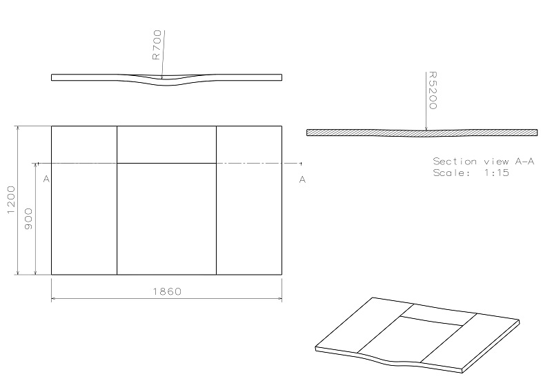
Hello forum! I've got a die plate that the surface is weared an deformed because of high temp and surface loads. I'm going to repair the surface using a 3-axis CNC mill. I've modeled the part in CATIA and created a sweeping operation with stepover equal to 5 mm (that gives the maximum scalop height of 0.2 mm) and extracted the g-code for SINUMERIK 880. The point is that our controller is out-dated and it's got very limited amount of memory (maximum of 108000 characters) and the file has 200,000 characters with linear interpolation (G1) movements . As you'll see in the drawing below the surface is actually consisted of infinite number of circular arcs. I searched the net to know how to get G2/G3 from the software, set the parameters but unfortunatley couldn't get G2/G3. Would you please help me? What's the problem?!
Thread: getting G2/G3 from CATIA
Results 1 to 8 of 8
-
05-31-2015, 05:57 AM #1
 Registered
- Join Date
- May 2015
- Posts
- 6
getting G2/G3 from CATIA
-
05-31-2015, 06:09 AM #2
Registered
- Join Date
- May 2015
- Posts
- 6
Re: getting G2/G3 from CATIA
-
05-31-2015, 08:29 AM #3
Registered
- Join Date
- Jun 2014
- Posts
- 13
Re: getting G2/G3 from CATIA
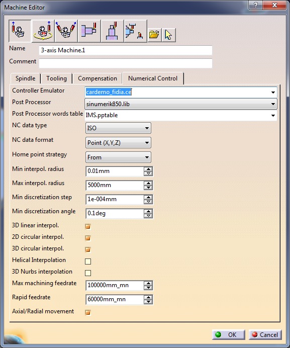
Are you sure post processor output G2/G3 ? Witch post processor do you use? Try to NC data format tab set X,Y,Z,I,J,K
-
06-01-2015, 12:40 PM #4
Registered
- Join Date
- May 2015
- Posts
- 6
Re: getting G2/G3 from CATIA
I use IMS post processor. Yes it does! I've even modeled a sample part that is less complex and successfuly got circular interpolation codes.
-
06-02-2015, 05:17 PM #5
Registered
- Join Date
- Aug 2008
- Posts
- 71
Re: getting G2/G3 from CATIA
If the path is offset normal to the surface, then it's possible that the tool path is not made of arcs.
If you are in a pinch, can you just break it in to 2 or 3 programs?Mark Rief
Siemens PLM
-
06-04-2015, 10:44 PM #6
Registered
- Join Date
- May 2015
- Posts
- 6
The path is not offset. It's a sweeping path done right on the surface with load equal to 0 mm. Actually I've done it before! That part is now get machined in 2 symmetric sections using mirror option with stepover of 5 mm. You know the surface finish is awfull after the process. The scallops are very high and there we will be leftovers in the line of separation. Does it have anything to do with the method of modeling? I draw sketches on different sections made some guides for it according to the draft, made a surface using multi-section solid and made a partbody using the created surface Originally Posted by markrief

-
06-13-2015, 01:33 PM #7
Registered
- Join Date
- Feb 2015
- Posts
- 123
Re: getting G2/G3 from CATIA
Are you using the IMSPPtable that comes in Catia from an install? I know on my system those PPTables are outdated and in my case would not work very well out of the box.
I purchased IMSPost Builder. When I went to the training I received an up to date PPTable that works correctly. Catia's business model is such that they want to force you to buy products from their Associate companies like IMS. None of the Post and PPTables out of the box will work to their full potential without spending the money for software like IMSPost or paying someone to build you a custom post.
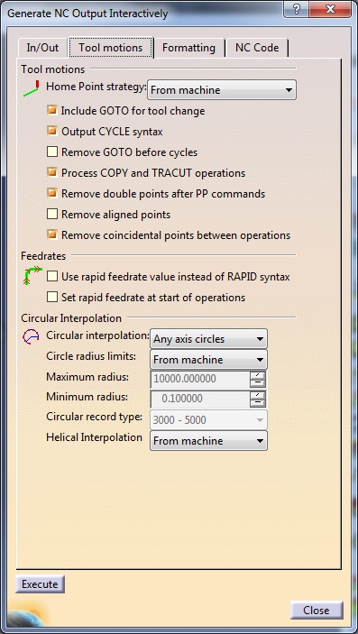
On the parts that I have 3D machined in Catia V6 I had to play with the parameters in the Post and the Max Discretionary settings in the tool path to get G2/G3 to output. Even in that case the finish was garbage. I ended up setting my MO settings to .0001" to get a finish. It of course put out extremely long code which sounds like is a problem with your machine
Rob
-
07-15-2015, 06:07 AM #8
Registered
- Join Date
- Dec 2010
- Posts
- 11
Re: getting G2/G3 from CATIA
Sorry this is late in coming, but I don't think the "Sweeping" operation in Catia will output arcs, regardless of the settings. Only a few of the machining operations in Catia support circular interpolation, and all arcs that ARE supported MUST lie in the plane perpendicular to the tool axis. Otherwise they will be converted to line segments. From the drawing, it looks like you might be trying to surface the part in question with a ball end mill oriented more or less perpendicular to the "flat" part. The arcs you would need lie not in the XY plane (G17) perpendicular to the tool, but in the ZX (G18) or YZ (G19) planes. Catia won't do this. It may be possible to do through advanced curve fitting algorithms in a post processor, but I guarantee a feature like that won't be present in any of the posts included with Catia. Another potential drawback is that many 3-axis milling machines are never really designed or tuned for true 3D work, as most typical ballbar inspections and test patterns are done solely to check XY circularity and accuracy. Little attention is usually paid to ZX and YZ accuracy, since the vast majority of 3-axis mill work, when you get right down to it is 2.5D anyway.

 Reply With Quote
Similar Threads
-
catia
By Rich05 in forum Uncategorised CAD DiscussionReplies: 2Last Post: 12-25-2013, 06:50 PM -
How many of you use Catia?
By Rich05 in forum SolidworksReplies: 6Last Post: 01-16-2009, 06:10 AM -
Catia
By forrey45 in forum OneCNCReplies: 3Last Post: 07-16-2007, 11:15 PM -
What is Catia
By cncadmin in forum Uncategorised CAM DiscussionReplies: 20Last Post: 05-20-2005, 10:17 PM -
Catia
By whiteriver in forum Uncategorised CAM DiscussionReplies: 5Last Post: 07-02-2004, 06:14 PM
