


This might be a little premature because I don’t have any preliminary design pics that I am ready to share, but I am working on a scratch build CNC mill design. The mill will be a weldment similar to what Dave DeCaussin made, but larger. I was poking at this idea before he posted his design, but his success confirmed the validity of this approach for me. This will be a long and slow process. I have three different weldment designs that I am working through and will evaluate based on rigidity and cost of the weldment. I am going to do a full analysis of the drive components and the structure, which I will post. I will also do some trades on component selection. After I finish the design, I am hoping that I will have the cash to move forward with it, but if not, I might try and kickstart it and see if I can get prices down through a group buy. If that doesn’t work, I will probably just post the drawings and see if anyone else wants to run with it.
I started down this road because of my BF20 conversion. It is painful to convert a mill to CNC that was designed to be a manual mill. I know I can do better with a scratch build; I am just not sure if it will be cheaper. My hope is the weldment I am designing will be as expensive as a new RF45 or close to it in price. I have looked at Tormach (Novakon is also an option). I like the machine and I will probably buy one before this is over, but I want more.
The machine I am working on will have linear rails throughout, a three HP up to five HP spindle motor, BT30 spindle, PDB, and if I can source one, an ATC. The travel for the mill will be somewhere between a Tormach and a Novakon. I am not sure what I will do for control software, but if I am working on that, then it is a good thing.
The first thing I am doing is working on some concepts and then I will start the mechanical/vibe analysis. After that, drawings and sending things out for quote. I have identified a few shops that specialize in machine fabrication and can manufacture the components from start to finish. All the mating surfaces will be ground.
One mistake I made on my BF20 build was not calculating the cost to finish the build, so for this build, I will do a complete price list down to wire and hardware.
I have found a good stand/enclosure is an important part of the design; I am going to make sure I spend time flushing this aspect of the design out. Also, the mounting points for the mill on the stand will be ground.
Finally, this should be fun; I enjoy doing design/analysis and this will help keep me sharp since I don't get to do it that often anymore.
Thanks for reading
Graham
Results 1 to 20 of 20
-
07-07-2015, 06:00 AM #1
 Registered
- Join Date
- Nov 2012
- Posts
- 220
Graham's Scratch Build Mill Design
-
07-12-2015, 10:42 PM #2
Registered
- Join Date
- Nov 2012
- Posts
- 220
Re: Graham's Scratch Build Mill Design
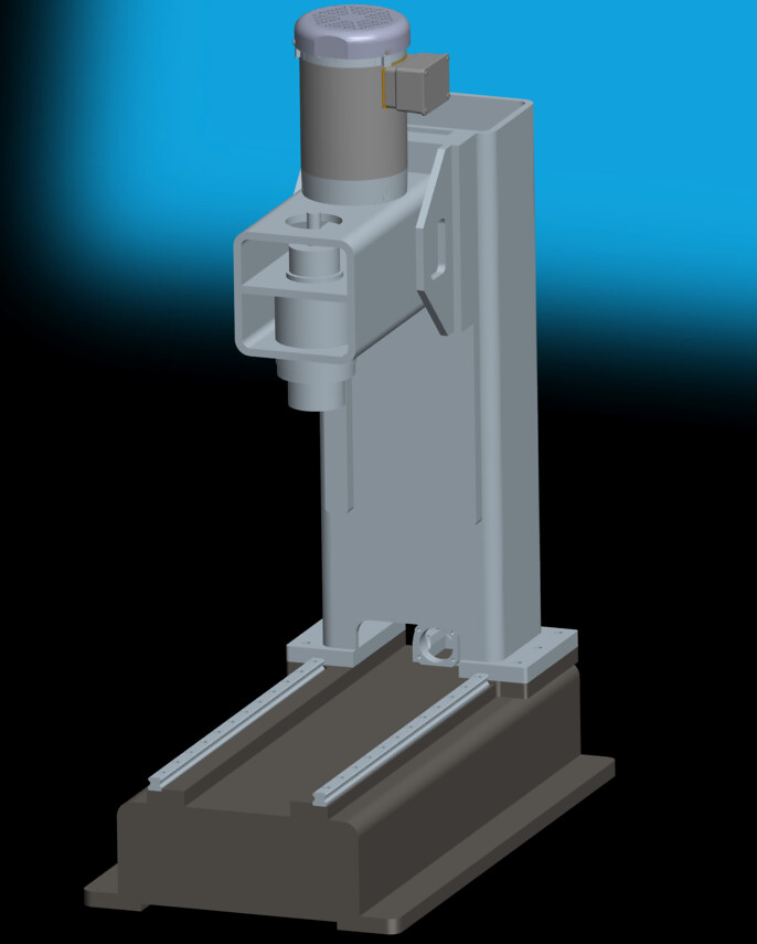
I thought I would post up a pic of a preliminary concept. I am tracking down parts so I can figure out how to size things. Once I get everything modeled up I can start dialing in column width, head design, table size, etc. Anyway here are a couple of pics.
-
07-13-2015, 05:44 AM #3
Member
- Join Date
- Sep 2005
- Posts
- 1195
Re: Graham's Scratch Build Mill Design
Nice small mill design, good rendering. Do you plan to fill the tubing with epoxy granite for weighting materials?
-
07-13-2015, 06:43 AM #4
Registered
- Join Date
- Oct 2010
- Posts
- 1189
Re: Graham's Scratch Build Mill Design
nice looks like my machine
 - which spindle do you intend to use ?
Gesendet von iPad mit Tapatalk
-
07-13-2015, 02:54 PM #5
Registered
- Join Date
- Nov 2012
- Posts
- 220
Re: Graham's Scratch Build Mill Design
Thanks asuratman. I will gusset the inside of the column and fill it with epoxy granite. I found a company that does it for you if anyone is interested: Originally Posted by asuratman

Zanite
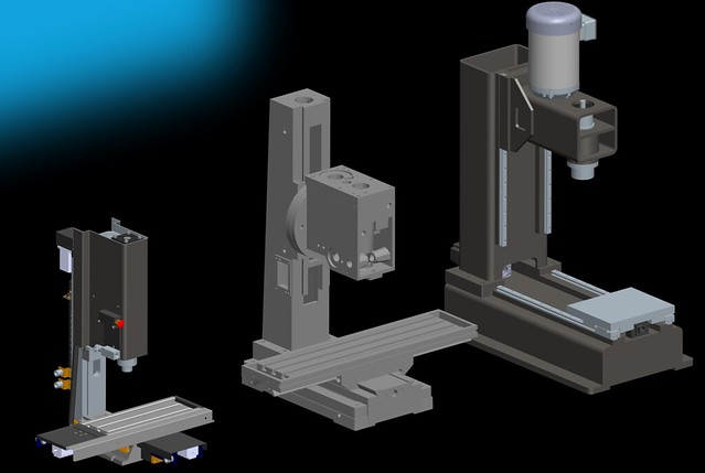
Also, for a reference of scale, here is a picture of the mill next to an IH RF45 and my BF20
@Tkamsker: I haven't seen it yet, but sounds like you have a good design:cheers: I would say I am pulling strongly from the VMC 15 design and the UMC 10 design which are both weldment based designs by Dave DeCaussin. As far as the spindle, I will either source one from China or see if someone like Dale Walsh will work with me. He has a kick starter page here:
https://www.kickstarter.com/projects...ge-and-spindle
It would be nice to keep the business local.
-
07-13-2015, 03:05 PM #6
Registered
- Join Date
- Oct 2010
- Posts
- 1189
Re: Graham's Scratch Build Mill Design
Yes walsh i have Seen But i bought last year an atc spindles from skyfire for my Mill But didnt receive it yet .....
Gesendet von meinem SM-G800F mit Tapatalk
-
07-13-2015, 03:11 PM #7
Registered
- Join Date
- Nov 2012
- Posts
- 220
Re: Graham's Scratch Build Mill Design
Here is a link to where I was thinking about getting the spindle: Originally Posted by Tkamsker
EN032# Spindle with synchronous belt for CNC milling BT30 ATC petal clamp+ disc spring+drawbar-in Machine Tool Spindle from Industry & Business on Aliexpress.com | Alibaba Group
-
07-14-2015, 08:39 PM #8
Registered
- Join Date
- Dec 2013
- Posts
- 72
Re: Graham's Scratch Build Mill Design
Looks great! I've developed a very similar design, pretty much the same inspiration from the Fadal VMC 10/15 and DeCaussin's UMC10. Only thing slightly different is additional gusseting on the exterior sides of the column to base mounting plate.
What is your designed wall thickness? I haven't been able to find anything greater than 5/8" at this point. What is your projected weight and travels?
Cheers,
Josh
-
07-15-2015, 05:16 AM #9
Member
- Join Date
- Sep 2005
- Posts
- 1195
Re: Graham's Scratch Build Mill Design
Comparing to an IH RF45 and my BF20, your machine size is quite big. You can use BT30 spindle. For the motor spindle, do you use high speed motor spindle with reducing pulley?
-
07-15-2015, 05:24 AM #10
Registered
- Join Date
- Nov 2012
- Posts
- 220
Re: Graham's Scratch Build Mill Design
Thanks hayes, do you have a picture of your machine/design? The wall thickness I have for the tubing is 1/2 inch. I column needs a lot of work; not sure if the cutout at the base is feasible, but makes things easier. If I keep the cutout, I am worried about clearance to do maintenance. The x travel will be between 20 and 24 inches, the y travel will be between 12 and 16, and the z travel will be between 15 and 20 inches. The mill will weigh approximately 1500 lbs by itself. That does not include epoxy granite filler. Originally Posted by hayes
-
07-15-2015, 05:33 AM #11
Registered
- Join Date
- Nov 2012
- Posts
- 220
Re: Graham's Scratch Build Mill Design
I plan on using a 3 to 5 HP motor with a vector drive. Probably a motor from Baldor, Leeson, or Marathon. I want to keep it simple and reliable. 3 HP is the largest I can go before I need three phase power. I do not plan to use a reducing pulley, the opposite. I think 6500 rpm would be good enough. Originally Posted by asuratman
-
07-15-2015, 10:36 AM #12
Registered
- Join Date
- Aug 2014
- Posts
- 889
Re: Graham's Scratch Build Mill Design
You can have 5 horse if VFD driven. Myself, for a weldment designed mill, where the column attaches to the base, you would be better off to have a full flange instead of split column design as in the pic.
Just my thoughts.
-
08-16-2015, 02:19 AM #13
Registered
- Join Date
- Aug 2015
- Posts
- 6
Re: Graham's Scratch Build Mill Design
Looking forward to seeing how you go with this as I'm planning a similar thing. I'm not too sure how yours will go being made from RHS. I think you will have major issues with chatter as it's just not stiff enough.
I'm planning mine from 20mm GR350 plate (off cuts from work), fully welded, stress relieved, then milled to dimension and finally, ground in the critical areas.
I'm fortunate to have a large 5 axis CNC horizontal borer at work to use after hours for my project, so i should only have to outsource the grinding, and i have a supplier that i use regularly for surface grinding that will do the job for some booze.
Looking forward to seeing how you go. And I'll certainly share my project once i get it started (have a project to do for the wife first)..
Good Luck Graham
JasonCut your way in... Weld your way out!!!
-
08-17-2015, 12:57 AM #14
Registered
- Join Date
- Jan 2012
- Posts
- 139
Re: Graham's Scratch Build Mill Design
Not sure how I missed this, SUBSCRIBED!
www.benchtopprecision.com
| BF20/G0704 Belt Drive Kits | X2 Mini-Mill Belt Drive Kits |
-
08-17-2015, 07:05 PM #15
Registered
- Join Date
- Aug 2009
- Posts
- 291
Re: Graham's Scratch Build Mill Design
Interesting. Have you considered the support under the base tube as those rails don't appear to be directly over the sidewall?
When I was at the steel store, I was staring up at some heavy wall tubing in the rust rack thinking just such a thing. But my vision for the base was 3 tubes. 2 outter standing on edge and the center lying flat to clear the screw.
Have you been following this?
http://www.cnczone.com/forums/vertic...g-machine.html
-
08-23-2015, 08:29 PM #16
Registered
- Join Date
- Nov 2012
- Posts
- 220
Re: Graham's Scratch Build Mill Design
G59, I agree completely about the split column. Intuitively it seems problematic and adds cost for the feature. I am curious how Fadal was able to do it though and not impact performance of their mill. Originally Posted by G59
Because of the size of the tubing, I agree chatter/resonance would defiantly be an issue. However, I plan on gusseting the column and base, which will increase the stiffness of the mill. I am also planning on filling the column and base with epoxy granite, which should eliminate the resonance issue. If I do a good job with the analysis, I will be able to identify the week points in the design and hopefully mitigate them. Worst case, I know the machines limitations.CrossfireX
Looking forward to seeing how you go with this as I'm planning a similar thing. I'm not too sure how yours will go being made from RHS. I think you will have major issues with chatter as it's just not stiff enough.
I'm planning mine from 20mm GR350 plate (off cuts from work), fully welded, stress relieved, then milled to dimension and finally, ground in the critical areas.
I'm fortunate to have a large 5 axis CNC horizontal borer at work to use after hours for my project, so i should only have to outsource the grinding, and i have a supplier that i use regularly for surface grinding that will do the job for some booze.
Looking forward to seeing how you go. And I'll certainly share my project once i get it started (have a project to do for the wife first)..
Good Luck Graham
Jason
I am defiantly jealous you have access to all of that equipment! That will save you a huge amount of money. Please post your design/build. It will be nice to see how you approach it.
I am not allowed to use our equipment at work due to liability issues…:bs:
LOL, thanks Scott. We will see how this goes...BTP
Not sure how I missed this, SUBSCRIBED!
Good call on the support flange, it would probably have caused the flange to warp excessively too after welding. Thanks for the link, I looked at it when he first started, but hadn't checked back in a while. I will spend the next two years designing this thing and he will be done with a working machine, lol.rocketflier
Interesting. Have you considered the support under the base tube as those rails don't appear to be directly over the sidewall?
When I was at the steel store, I was staring up at some heavy wall tubing in the rust rack thinking just such a thing. But my vision for the base was 3 tubes. 2 outter standing on edge and the center lying flat to clear the screw.
Have you been following this?
http://www.cnczone.com/forums/vertic...g-machine.html
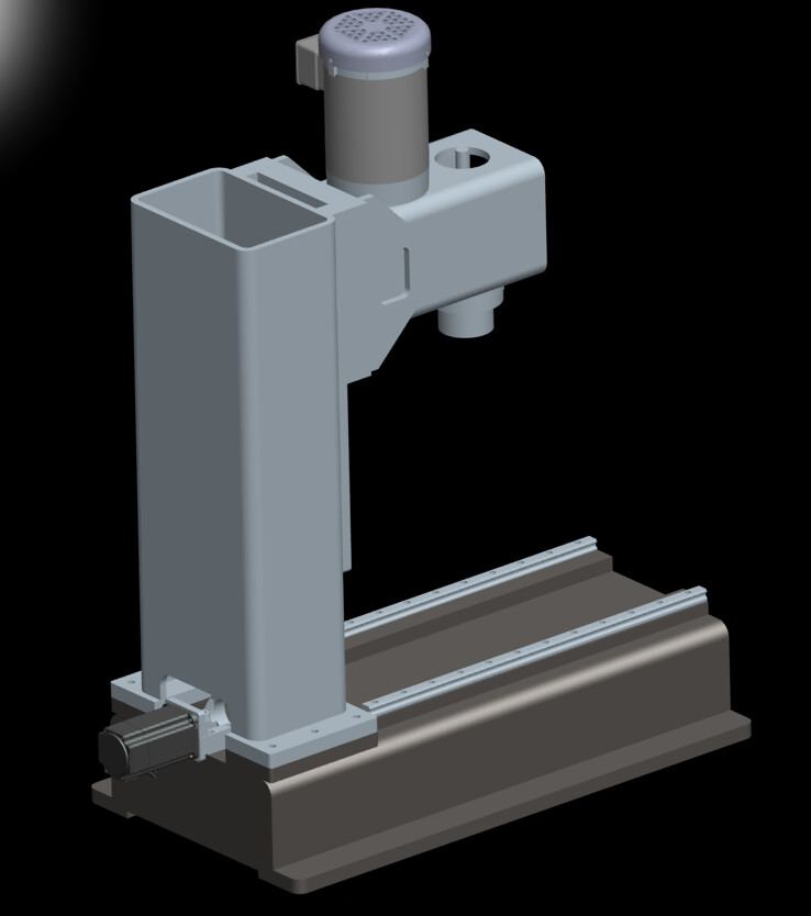
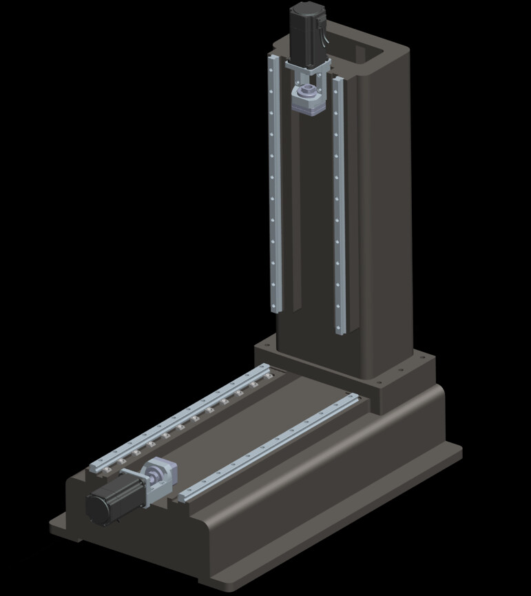
Here is a pic of the design with some slight updates from your guys comments:
-
08-23-2015, 08:52 PM #17
Registered
- Join Date
- Aug 2014
- Posts
- 889
Re: Graham's Scratch Build Mill Design
gcofieldd,
save yourself a bunch of money.
I said it before in another thread and I'll say it again, fill the void of the column with oil impregnated sand. Regular playground or beach sand you can buy at Lowes. When the sand is packed in the column, it will absorb 99% of all the vibrations that Epoxy Granite will. Just make sure to fill any voids in the column.
The difference is cost. $5-$10 compared to $200-$300.
Also when I say impregnated, I don't mean soaked so that it leaks all over the place.
If you think about it, your rigidity comes from the steel tube, not the EG. If you haven't sandblasted the inside of the steel tube, over time through temperature cycling in the shop and constant vibrations, the EG mix will separate from the vibration prone steel tube. Yes Epoxy shrinks with age. They all do, however minute.
Following this thread with interest.
-
09-06-2015, 12:24 AM #18
Registered
- Join Date
- Aug 2015
- Posts
- 6
Re: Graham's Scratch Build Mill Design
Hi mate, how's the progress?
I've put a little bit of time into my design while at work (in my lunch breaks of course ;D ) and i realized just today that my design is actually very similar to yours, except I'm using plate, welded rather than RHS. I'm keen yo see your progress, and once i have the retaining wall finished in the front yard, I'll be back onto the mill. keep us all posted.
cheers
JasonCut your way in... Weld your way out!!!
-
01-24-2016, 03:16 PM #19
Registered
- Join Date
- Dec 2011
- Posts
- 155
Re: Graham's Scratch Build Mill Design
I have also spent some time designing a large weldment cnc. I ran many FEA's and many design iterations, as well as costing out components. I estimated my design to be around 3000+ lbs finished. For mine, the cost of all the components, material, and labor for the things you cannot do yourself would add up to be more than what you can buy a used VMC, and the finished product would not be as nice. I found a used boss cnc that I am going to retrofit, now the dream of building a VMC seems so unrealistic. I figured mine would probably cost over 10K when finished, that's much better than a new haas tm1 or mini mill, but like I said, I can get a working used vmc for less than that.
If you want I would be happy to help with design
-
01-24-2016, 06:59 PM #20
Registered
- Join Date
- Nov 2012
- Posts
- 220
Re: Graham's Scratch Build Mill Design
I agree 100%. You can definitely get a used VMC cheaper and I may go that route when everything is said in done. But, I would still like to go through the motions and do the design. I also want to post the cost info, so everyone can see how it plays out. I know a number of forum members have gone through the motions, but I have not seen anyone post their design and cost data up. Originally Posted by dbsharp
Work has been slowing me down and I am still working on my BF20, along with other projects, but I will have some progress in a bit to post up. I appreciate your offer for help, I may take you up on it.
The funny thing is, you can make this mill with a MIG welder and a good Bridgeport, so I may get this done yet. What I may have to cutout is the Blanchard grinding.

 Reply With Quote
Similar Threads
-
Graham's Optimum BF20 Build
By gcofieldd in forum Benchtop MachinesReplies: 191Last Post: 04-29-2022, 12:34 PM -
Scratch build small mill
By dick cnc in forum Benchtop MachinesReplies: 51Last Post: 04-29-2014, 12:51 AM -
Project: Aluminum Eater (Scratch Build) - New XY-base frame design!
By LBSamurai in forum CNC Wood Router Project LogReplies: 5Last Post: 12-06-2011, 10:47 PM -
DIY CNC Precision Mill Design&Build
By RogerRetro in forum Uncategorised MetalWorking MachinesReplies: 12Last Post: 03-19-2008, 08:09 AM -
Scratch Design Questions
By danowar in forum DIY CNC Router Table MachinesReplies: 7Last Post: 12-30-2003, 11:16 PM
