


Hello again!Originally Posted by tandel

The PID algorithm is very very simple. The output of the PID will be the duty that will be applied to PWM channels (basically the power applied to motor. Below is the basic algorithm. You will note there is no time involved because the PID updates at a constant rate.
Position_Error = Encoder_Position - Requested_Position;
int32_t Output = Position_Error * Kp;
Integral += Position_Error * Ki;
Output += Integral;
Output += (Position_Error - Old_Position_Error) * Kd;
Old_Position_Error = Position_Error;
Now... We have to apply this output as duty to PWM channels. Please note that this implementation uses trapezoidal logic (basically meaning that only 2 outputs for the motor can be active at one time). If you want to use all 3 of them you will need to build somekind of a sinusoidal commutation matrix. (search the net for it there are tons of examples and explanations). For the DC motor things are simpler as there will be no commutation between phases as only 2 of them are used.
Using l6203 as driver is possible. You will have to alter the code a little. You will have to use only channels TIM1CH1 and TIM2CH2 (forget about the complementary channels) and do something like this in PWM_Set_Duty
void PWM_Set_Duty_DC(int16_t duty)
{
duty = Check_Max_Current(duty); // this is current limiting do not remove
if(duty > 0)
TIM1->CCR1 = duty;
else
TIM1->CCR2 = - duty;
}
Mihai.
Results 101 to 120 of 490
-
11-09-2015, 09:12 AM #101
 Registered
- Join Date
- May 2006
- Posts
- 190
Re: DIY BLDC / DC Motor Servo Drive - ARM MCU (STM32F103C8T6)
-
11-09-2015, 09:13 AM #102
Registered
- Join Date
- May 2006
- Posts
- 190
Re: DIY BLDC / DC Motor Servo Drive - ARM MCU (STM32F103C8T6)
You are correct! That is in fact what they are selling with the name DC Servo Motor. Originally Posted by Stigoe
-
11-09-2015, 09:19 AM #103
Registered
- Join Date
- May 2006
- Posts
- 190
Re: DIY BLDC / DC Motor Servo Drive - ARM MCU (STM32F103C8T6)
Well with a 4000 PPR encoder I was able to achieve about 3000RPM (counting both channels of the encoder) for the motor... That means about 200KHz input from the encoder... I would say the step input can count pretty much the same... there is also a step multiplier if your CNC Software / Hardware setup can not generate steps at that rate... Originally Posted by cjmerlincnc
Mihai
-
11-09-2015, 05:37 PM #104
- Join Date
- Oct 2015
- Posts
- 44
Cool explaination ..another thing is why are you using adc here with current control why this current control loop is needed and where to put on above equation? Also I have read microchip bldc made easy but they are using hall serson to drive hall sensor but I think you are using encoder to drive bldc so what is working logic behind it ? And one more thing is is it cascade control pid in which pid rus inner side of loop and outerside loop runs .....another thing is is are you using feedforward here with pid? Originally Posted by mcm_xyz
-
11-09-2015, 08:58 PM #105
Registered
- Join Date
- May 2006
- Posts
- 190
Re: DIY BLDC / DC Motor Servo Drive - ARM MCU (STM32F103C8T6)
Just to be clear... I do not think you can use the L6203 to drive a BLDC that is triphasic still. Originally Posted by tandel
Current sensing is very important. Without it you will blow circuit tracks, fuses and eventually the power stage of your circuits. The short circuit current in a motor is usually way higher than max allowed current so that is the problem. it's a MUST when you want to drive bigger motors.
The principle behind using only the encoder and no hall sensors is easy too. First we apply power to 2 chosen phases. This will force the motor to align (move freely) toward a motor pole. In this position we reset the encoder to 0. From here we calculate from the encoder absolute position the shaft angle. and from here the commutation phase (like the one generated by the hall sensors). Look in the code... all is there... File. pwm.c is of main interest.
Mihai
-
11-10-2015, 03:29 AM #106
- Join Date
- Oct 2015
- Posts
- 44
 Re: DIY BLDC / DC Motor Servo Drive - ARM MCU (STM32F103C8T6)
!!!!!!!!!!!!! wow !!!!!!!!!!!!!!!!woohooo!!!!!!!!!
ya you are right l6203 does not drive bldc because i need three half bridge and l6203 has two of them only , okay good and other thing is here current control is only for safety it is not part of pid that is what you want to say? correct me if i am wrong . also i had some reading on how to drive bldc with hall sensor and i have implemented but never tried encoder to drive bldc so it will be more interesting. thanks for your valuable reply...i have my stm32 board arrived but i think i need to buy stvlink2 to programme it ..but even if i buy stvilnk2 i dont have any idea how to programme this board or which ide do i need to write this code and which software tools needed ..as we useusbasp , avrstuido and avrduddess to programme avr..need some direction on that !
-
11-10-2015, 03:57 AM #107
- Join Date
- Oct 2015
- Posts
- 44
Re: DIY BLDC / DC Motor Servo Drive - ARM MCU (STM32F103C8T6)
i have been seraching but not find that how and why that error led turn on and make driver disable ? what is that condition that we have to disble to driver and error led on ? i have read some about integral windup...so can you give some explanation on that error handeling and how to do that in code ? appriciate your help .
-
11-10-2015, 05:24 AM #108
- Join Date
- Oct 2015
- Posts
- 44
Re: DIY BLDC / DC Motor Servo Drive - ARM MCU (STM32F103C8T6)
are you using hardware inturuppt to read qudreture encoder and mach3 input ? or timer ?
-
11-10-2015, 08:19 AM #109
Registered
- Join Date
- May 2006
- Posts
- 190
Re: DIY BLDC / DC Motor Servo Drive - ARM MCU (STM32F103C8T6)
Plenty of examples on the net on how to setup eclipse or other C environment in order to compile... setting up stlink is easy. Install STLink utility and plug it in. Connect the 4 wires from the stm32f103 board to the stlink. Use utility to load and flash bootloader.bin and stm32f103servo.hex
Respect the pinout for stlink and the development board:
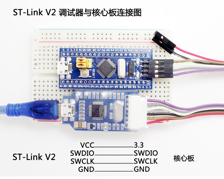
There is an if inside PID_Update that checks if current error is higher than max allowed error. There is the error led turned on.
We use timer (TIM2) to count the quadrature encoder from the motor and exti to count steps from the Step / Dir inputs.
Form what I can evaluate your expertise I suggest you start with small steps.
1. Build exactly the schematic provided.
2. Try first to flash provided binaries.
3. Try to see if you have usb connection with the Tuner software.
4. If so configure the servo drive the right way
- set a low current limit for the motor... say 300 mA
- set the correct values for encoder ppr and motor poles.
- set lets say 100 in Kp, 0 in Ki and Kd.
5. Try to see if the motor moves with "move 1000" command.(1000 is the number of steps you can enter what you want)
Please do not try to do all stuff from the first step. There are lots of places you may fail and the error can be hard to find...
Mihai
-
11-10-2015, 12:46 PM #110
- Join Date
- Oct 2015
- Posts
- 44
Re: DIY BLDC / DC Motor Servo Drive - ARM MCU (STM32F103C8T6)
thanks for your good advice .
i also had worked on below link but at more than 300 rpm things get worse
https://www.youmagine.com/designs/dc...gn-information
i was using mach3 at 25000hz frequency
encoder was 1000cpr
powersupply voltage 24 volt 3amp
motor rated viltage 24 , moror has two brush
l6203 used to drive brushed dc
this is video that shows motor is misiing target
https://www.youtube.com/watch?v=uiOBqyYuYfo
so as you suggested i will do everything step by step
first as i get my stvilnk i will do things as you suggested first !
thanks mihai you saved me !
-
11-10-2015, 01:01 PM #111
Registered
- Join Date
- May 2006
- Posts
- 190
Re: DIY BLDC / DC Motor Servo Drive - ARM MCU (STM32F103C8T6)
Do you have access to an oscilloscope? Even a very slow pocket one like mine... Please check how the signal from the encoder looks like on the pins on the MCU (after opto or whatever circuitry you have there). I am pretty sure the signal does not look square as it should... they probably look like this: Originally Posted by tandel
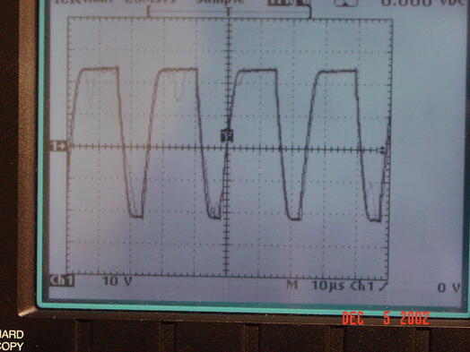
if the signal shape is not good, you will have problems especially when increasing speed...
Buy an oscilloscope... It's worth all it's money...
Mihai
-
11-10-2015, 02:48 PM #112
- Join Date
- Oct 2015
- Posts
- 44
Re: DIY BLDC / DC Motor Servo Drive - ARM MCU (STM32F103C8T6)
hi Mihai
i dont have oscilloscope rightnow so..
is there any hardware solution that i can use to tackle this encoder problem ? like flip flop or 74ls04 something like that
-
11-10-2015, 04:05 PM #113
 Registered


- Join Date
- Mar 2005
- Posts
- 304
Re: DIY BLDC / DC Motor Servo Drive - ARM MCU (STM32F103C8T6)
because your project use interrup for ENCODER counter Originally Posted by tandel
in Mihai project, STM32 have build in harwawre encoder decoder, it can work high pluse encoder
-
11-11-2015, 05:21 AM #114
- Join Date
- Oct 2015
- Posts
- 44
 Re: DIY BLDC / DC Motor Servo Drive - ARM MCU (STM32F103C8T6)
hi actually i was comparing this with elm chan based servo which is achieving around 2000-3000 rpm Originally Posted by tivoidethuong
Re: DIY BLDC / DC Motor Servo Drive - ARM MCU (STM32F103C8T6)
hi actually i was comparing this with elm chan based servo which is achieving around 2000-3000 rpm Originally Posted by tivoidethuong
depend on encoder and he used attiny2313 and written asmbly langage so his controller may be fast with asm but even if i am using arduino language i should get around 1000 rpm minimumwith atmega328 ..
-
11-11-2015, 05:52 AM #115
Registered
- Join Date
- Mar 2005
- Posts
- 304
Re: DIY BLDC / DC Motor Servo Drive - ARM MCU (STM32F103C8T6)
ELM - DC Servomotor Controller Originally Posted by tandel
The maximum count rate of the software sampling method is less than its sampling rate. If input count rate exceeds the sampling rate, count error will occur and the correspondence between actual motor position and current position register will be lost. At the SMC, to increase over speed tolerance, a special process is applied to the error code. It can accept input count rate up to two times faster than its sampling rate. Therefore, the maximun input count rate is up to 104k cps. When a 400 ppr (1600 cpr) incremental encoder is used, the maximum rotation velocity becomes:
Actually, the maximum count rate will little decrease from above value due to the jitter of interrupt response time and mechanical accuracy of the encoder.
-
11-11-2015, 06:05 AM #116
- Join Date
- Oct 2015
- Posts
- 44
Re: DIY BLDC / DC Motor Servo Drive - ARM MCU (STM32F103C8T6)
hi tivoidethuong
can u please explain that special proceese which is applied to code by elm to increase speed tolarance../
and let me clearify some thing i have 1000cpr encoder and brushed dc motor and i think it is not servo optimised
1.i was using servostrap02 it was coutingencoder at 4x and at 300 rpm i rotate my motor 1000 revolution back and forth and it has accuracy going more than that around 500rpm misses position going more than that motor gose out of control at full speed
2. i used servostrap0 and i have changed code to only count 1x so speed should be 4times more but it all goes wrong
give me direction
-
11-11-2015, 08:27 PM #117
Junior Member
- Join Date
- Nov 2015
- Posts
- 1
I want to know that in AVR development why you removed the sinusoidal commutation tables and went to square wave commutation.
Because as per mye xperience about servo control, the sinusoidal commutation is always referred as the best method providing the smoothest torque.
Did you see the opposite? Or was it just that the advantage from sinusoidal commutation was not noticeable and it certainly is easier to implement the trapezoid commutation with limited resources like AVR.
prototype pcb assembly
-
11-11-2015, 10:27 PM #118
Registered
- Join Date
- Jan 2006
- Posts
- 115
Re: DIY BLDC / DC Motor Servo Drive - ARM MCU (STM32F103C8T6)
sinusoidal commutation is good for continuous rotation applications like model airplane motors and the like. Not advantageous for servo use, especially at very low speeds, where maximum control of the exact position is required. most of the app notes and such I have seen regarding driving BLDC motors are more appropriate for things like fan motors that need to spin at high speeds with a big emphasis on smoothness and power efficiency.
My own brushless motor driver I built a few years ago for a particular positioning application used hall sensors and a very simple truth table. used very little code, written in bascom and was good for several thousand rpm's (never fully tested the maximum speed). Much simpler and faster than a sinus table. You'll notice that many sinusoidal schemes also use back EMF rather than actual sensors, once again good for continuous rotation in the same direction, not much good a low rpm's and useless for accurate position holding while stopped.
-
11-12-2015, 12:40 AM #119
Registered
- Join Date
- Mar 2005
- Posts
- 304
Re: DIY BLDC / DC Motor Servo Drive - ARM MCU (STM32F103C8T6)
step 1, you need check encoder signal with osc Originally Posted by tandel
-
11-12-2015, 08:46 AM #120
Registered
- Join Date
- Mar 2005
- Posts
- 304
Re: DIY BLDC / DC Motor Servo Drive - ARM MCU (STM32F103C8T6)
hi mihai, i want use 26lv32 for encoder interface , How do you think?
next ver, i want change to 64 or 100pin stm32, can you help me code?
thanks

 Reply With Quote
Similar Threads
-
servo drive for Fanuc A06b-0116 servo motor, Help
By Cblad in forum FanucReplies: 3Last Post: 02-11-2015, 06:07 AM -
NEED TO KNOW WHICH YASKAWA SERVO DRIVE AND SERVO MOTOR ON EXCITECH E5 HEAVY-DUTY
By M.Abid in forum Excitech routersReplies: 0Last Post: 10-21-2014, 09:29 PM -
Servo Drive AC + servo motor for car steering wheel simulator
By yusukeand in forum Servo Motors / DrivesReplies: 6Last Post: 01-10-2014, 09:06 AM -
VCE-750 with BLDC Servo - X Axis Servo fault
By kostner in forum Haas MillsReplies: 6Last Post: 10-23-2011, 08:09 PM -
Sell Servo Motor, Servo Drive by GSKcnc.com from China
By salecnc@hotmail in forum News AnnouncementsReplies: 0Last Post: 06-03-2008, 08:55 PM
