


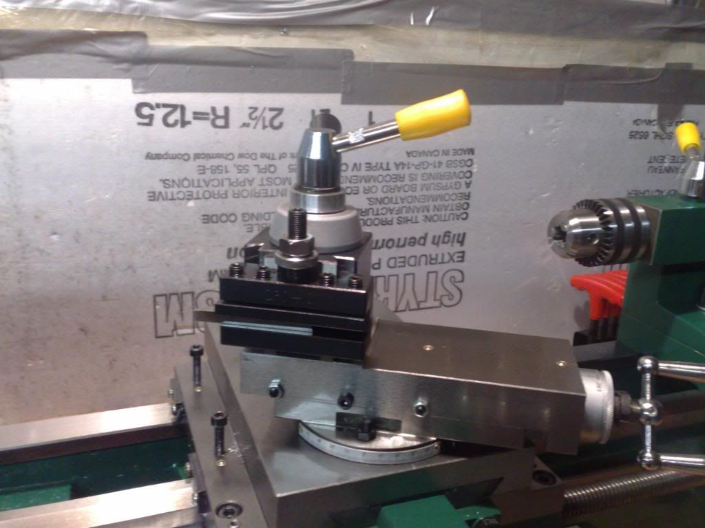
Just got the QCTP today and I made the screw to hold it down and bushings on both ends. I didn't want to throw away the old lever so I used it instead of a nut:
Now I'm planning of making a milling attachment for the lathe. I already have an angle plate of size 3" x 3" and I want to mount it on the compound where the toolpost is. But now I'm stuck because I can't find a cheap (<100$) and small dovetail slide to provide the z-axis movement. Any suggestions for a cheap dovetail slide? thx
Thread: Busybee 10 X 18
Results 241 to 260 of 260
-
07-08-2009, 07:25 AM #241
 Registered
- Join Date
- Jun 2009
- Posts
- 8
-
07-16-2009, 11:23 PM #242
Registered
- Join Date
- May 2008
- Posts
- 14
Hi guys : thanks for all the advice you're providing! I have 2 questions:
- I'm about to replace the half nut - any advice on the disassembly/assembly? Anything to be looked at while it's torn down?
- has anyone done any left hand threading on the the lathe ? I'd like to try it but don't know where to start the mods.
Thanks in advance
-
07-16-2009, 11:59 PM #243
Registered
- Join Date
- Oct 2008
- Posts
- 53
Haven't done the half nut, did something go bad on your lathe? I have done lefthand threads, pretty easy mod. Just welded an arm on the one side for the transfer gear and turned down a bolt for locking it into place. Also used a brass bushing for it ride on instead of messing with bearings. Works perfect.


Clinton
-
07-17-2009, 02:22 AM #244
Registered
- Join Date
- May 2008
- Posts
- 14
Thanks Clinton but could you give a bit more detail on the mod for the transfer? The half nut (I believe) is quite worn probably due to my sloppy judgement on the threading dial. However I do believe the previous owner used it rather than the carriage lock!
-
07-17-2009, 03:07 AM #245
Registered
- Join Date
- Oct 2008
- Posts
- 53
What do you need to know? The gear doesn't matter for # of teeth it's just to reverse the travel. Just work you gear ratio as you normally would without the reverse tumbler and stick whatever gear between that fits properly. I know this sounds wrong but trust me that's how it works. Originally Posted by cr17

Clinton
-
07-17-2009, 10:32 PM #246
Registered
- Join Date
- May 2008
- Posts
- 14
Clinton: so by positioning the transfer gear there it reverses the direction of the leade screw? Could you send a picture of the arm and weld position? Also is the bolt free floating or does it need to be welded in place?
Thanks for your patience with all these questions
-
03-10-2010, 07:01 PM #247
Registered
- Join Date
- Mar 2010
- Posts
- 0
Hi Everybody
Regarding cutting threads with this lathe: I'm sure that many of you have figured this out but I thought I might save a few of you some headscratching time. If you are using a program like GearsVB to calculate oddball threads it is important to note that gear A is not directly driven by the spindle, which is assumed by the program. There is a 4x gear reduction, so for cutting metric threads multiply your desired pitch by 4, and for imperial threads divide your tpi by 4 before entering it into the program. I just cut my first thread with it yesterday (M4x0.8).
-
03-10-2010, 10:46 PM #248
Member
- Join Date
- Feb 2010
- Posts
- 0
Anyone seen this model in the US?
-
03-11-2010, 04:11 PM #249
Gold Member
- Join Date
- Jul 2007
- Posts
- 1602
This is quite similar: http://www.machinetoolonline.com/PM1027.html Originally Posted by knudsen
The main difference is that the bed is longer (not a bad thing). It is more expensive however it includes a stand and a lot of accessories that don't come with the Busy Bee version.
bob
-
08-05-2010, 09:18 PM #250
Registered
- Join Date
- Aug 2010
- Posts
- 0
I'm just new to this forum and to the BusyBee 10X18. My lathe was bought second hand but hardly used. It seems to be cutting a taper of about .008" in 4' which is a bit much! Is this hard to correct? It is smaller at the tailstock end of the cut. Also do metric threads have to be cut by leaving the leadscrew engaged and reversing the direction? Is the thread dial used for metric threads? Sorry for the lack of knowledge but I'll be a quick learner! Thanks
-
08-05-2010, 11:51 PM #251
Member
- Join Date
- Feb 2010
- Posts
- 0
Thanks for the link, Bob. I missed your reply until now :rainfro:
Gramps, I think that means your work is closer to the tool at the tail than the head. You should be able to see that much difference if you put dead centers in both ends and bring them together. If you can't see it, you can put a straight edge flat between the centers, then gently bring the center in the tail in to tighten it slightly, and the side that's off will move away from the tail. For testing horizontal alignment, you will want the long edge horizontal, the width of the ruler vertical and the thickness of the rule pinched between the centers. Flip the length so it's vertical to test vertical alignment.It is smaller at the tailstock end of the cut.Wen I was young, I spent most of my money on fast women, slow horses, and cheap booze. The rest of it I just wasted.
-
08-06-2010, 12:37 AM #252
Registered
- Join Date
- Nov 2007
- Posts
- 616
Click the BUY NOW button, Jon!! :rainfro: Originally Posted by knudsen

-
08-06-2010, 12:38 AM #253
Member
- Join Date
- Feb 2010
- Posts
- 0
Out of cash, and out of stock LOL Originally Posted by blades
Wen I was young, I spent most of my money on fast women, slow horses, and cheap booze. The rest of it I just wasted.
-
08-06-2010, 12:40 AM #254
Registered
- Join Date
- Nov 2007
- Posts
- 616
No problem, PEFCU will take good care of you!

-
08-06-2010, 12:42 AM #255
Member
- Join Date
- Feb 2010
- Posts
- 0
Trying to get out of debt!:rainfro:
Wen I was young, I spent most of my money on fast women, slow horses, and cheap booze. The rest of it I just wasted.
-
06-09-2011, 12:42 PM #256
Registered
- Join Date
- Jun 2008
- Posts
- 614
DTE 24 is good for hydr. oil and gear oil...we use it at work in the VMC's for both applications Originally Posted by DSL PWR
http://www.g0704.blogspot.com/
-
11-24-2011, 03:14 AM #257
Registered
- Join Date
- Dec 2010
- Posts
- 0
This is a reply to a very old post.
When you buy the Craftex B2227L 10"x 18" lathe, before you even turn the lathe on (after you have levelled it horizontally and laterally), visit your local NAPA dealer and pick up some Victor Reinz JV127 1/32" gasket material. It comes in a sheet 12"x 24". Replace the gasket on the gear box cover. It will save you lots of grief!
The gear box cover gasket is poorly designed and oversized. There's a groove on three sides of the gear box case - front, back, and right side. On the right side is a "sump hole" that goes into the spindle bearing. As the gears spin around, the oil is splashed onto the top of the cover. It seeps into the groove and down into the sump hole to lubricate the spindle bearing.
Because the gasket is oversized, it covers the front groove thereby restricting the flow of oil into the spindle bearing. At higher speeds after a few minutes, you will hear a clicking sound. That's due to the lack of oil on the spindle bearing.
To cut a new gasket, remove the cover from the gear box and place it on top of the gasket material. Using the cover as a pattern, cut a piece of gasket material. Next measure, trace and cut a 1/2" rectangle around all four sides of the gasket material. You now have a new gasket - but without any screw holes.
To cut the screw holes in the gasket, place the new gasket on top of a piece of scrap plywood and place the cover on top of the gasket. Clamp the plywood and cover together. Using an appropriately sized drill bit, drill holes in the gasket material using the cover as a guide. The JV 127 gasket material will produce a nice clean screw hole.
Reinstall the new gasket and the gear box cover.
-
11-28-2011, 03:03 AM #258
Registered
- Join Date
- Dec 2010
- Posts
- 0
Trying to figure out all the bits and parts of my Craftex 10"x 18" metal lathe. Kevin Millard from Sudbury had a bunch of really good YouTube videos on the lathe but he somehow took them down.
Between some experimentation, looking at other videos, and trips back and forth to Busy Bee Tools, I've managed to learn quite a bit more about my lathe than what I knew two weeks ago. First the Cross Slide locking nut, then Compound Slide gibs, and now the Cross Slide gibs.
Here's the first bit. We'll add more photos in the days to come.
Kevin had a neat trick for keeping some tension on the cross slide locking nut. He installed a spring between the carriage and the locking bar. Click on the thumbnail to see a larger photo.
-
02-17-2020, 07:35 PM #259
Member
- Join Date
- Feb 2020
- Posts
- 4
Noy sure if you ever came across the info you were looking for, as far as manuals goes, i have the Craftex B2229 combo machine, and found far more information and initial set up information in the grizzly counterpart... as in a 10 page craftex manual compaired to a 120 page grizzly manual... if i find the digital copy i made of it, ill send it you you, or post is as a link or something... new the the forum. Originally Posted by nickm23
-
02-18-2020, 12:45 AM #260
Member
- Join Date
- Feb 2020
- Posts
- 4
Smithy industries has a whole set of videos on adjusting one of their machines... its not going to be exactly like your machine but will give you a few things to look at for adjusting and removing back lash form slides and ways. Originally Posted by ClintonH
here is their you tube home page link, check under the video playlist section.
https://www.youtube.com/channel/UCau...K4v20NzWlUTF0A

 Reply With Quote