


Hello can someone point me the right direction.
Looking to upgrade my cnc router to have plasma capabilities.
Looking for a 101 guide to cnc plasma.
I have some basic questions I need answered.
1. Looking for a basic wiring diagram for adding a thc to generic bob and overall circuits required for plasma add on to a cnc
2. Whats required for grounding for a cnc and electronic. What is different from cnc router.
3. What kind of plasma is required, Blow-back start technology or*..induction start. Or HF starting/Pilot Arc
4. If you only have HF starting/Pilot Arc what mods can you perform to still use it.
5. Do you need cnc port on your plasma machine, can you mod a machine with out it.
6. Why do you need a cnc port ... ie advantages?
7. Please can a moderator make this a sticky... for future plasma users referance
Thread: plasma newbie 101 questions
Results 1 to 20 of 21
-
02-28-2016, 06:48 AM #1
 Registered
- Join Date
- Apr 2006
- Posts
- 1016
plasma newbie 101 questions
-
02-28-2016, 06:59 AM #2
Registered
- Join Date
- Apr 2006
- Posts
- 1016
Going to answer some of my own questions trying to make this one stop 101 sticky on plasma cnc
Below comment was comment was found in another thread
credit given to
Jim Colt Hypertherm
A pilot arc on a plasma torch is an arc that will fire in the air, away from the material being cut. A pilot arc is a low powered plasma arc that makes its current path between the negative electrode and the more positive nozzle, and it is designed to allow the arc to transfer quickly to metal plate regardless of the surface finish...as it has adequate power to burn through the surface and make electrical contact. Once the pilot arc does make contact with the material, this is sensed, the main arc current ramps up (pilot arc circuit disconnects the nozzle from positive as the plate is not positive) and full power cutting begins.
-
02-28-2016, 07:42 AM #3
Registered
- Join Date
- Apr 2006
- Posts
- 1016
eliminate noise interference.
Credit given to flyinwilly
1) Ran my motor cables with shielded, twisted pair, with a drain wire.
(2) Moved my PC at least 20' away from the table or it would go bonkers and ruin a job.*
Also covered parallel port cables in grounded, flexible metal conduit.
(3) Install separate earth ground for the table, cutter case, electronics box, etc.
-
02-28-2016, 08:24 AM #4
Registered
- Join Date
- Apr 2006
- Posts
- 1016
Re: plasma newbie 101 questions
Attached is a basic interconnection over view of thc control I found online, does someone have a drawing simular to this including the bob interface . I'm currently using a smooth stepper and not sure how this would change on the interface using ethernet port and the bob and mach3
Attachment 309920
Sent from my SM-T810 using Tapatalk
-
02-28-2016, 03:11 PM #5
Registered
- Join Date
- Apr 2006
- Posts
- 1016
Re: plasma newbie 101 questions
The role of a torch height control system for mechanized cutting systems is often understated. A good THC is absolutely critical to good cut quality. It is a known fact that by far the best possible control*method is by sensing the cutting voltage. The cutting voltage is directly proportional to the height between the torch and the workpiece; higher the distance, higher the voltage and vice versa. So one can*easily take the cutting voltage as a control parameter and use the same for controlling the stand-off distance. This method of control is frequently referred to as AVC (arc voltage sensing). Sensing the arc*voltage is not devoid of challenges. The torch is subjected to a high frequency pilot arc, which creates plasma. This HF can easily traverse back to the sensitive voltage measuring circuitry and damage/ cause*malfunctioning of the system. It is absolutely essential to isolate the measuring circuitry from the plasma HF and yet be able to measure the voltage accurately. Highly sensitive arc voltage control circuitry can*detect voltage variations less than 0.5V. Accurate measurements as well as isolation can be achieved through use of Hall sensors.
Piercing through thick metals has an adverse effect on the life of the torch consumables. Hence, piercing needs to be carefully controlled in order to maximize the life of consumables. A proper piercing*sequence is explained below with schematics:
i)*When a command is received from the CNC to start cutting, the torch height controller moves the torch down to touch the workpiece, to ascertain zero level. See Fig. a. Plate can be sensed through multiple mechanisms, most commonly used is ohmic sensing/ motor*torque sensing/ a combination of both. Once the plate has been sensed, the torch now moves upwards (see Fig. b)
ii)*The torch continues to move upwards to a programmed piercing height. On reaching this height, the plasma arc strikes and the plate begins to get pierced (fig c). While piercing takes
place, a lot of molten metal (depending on the thickness of the plate being pierced) jumps out of the plate and forms a pool. The torch needs to be protected from this molten metal,so the torch continues to move upward to a programmed “molten pool jump” height. (fig. d)
iii)*The torch now moves downwards to the programmed cutting height. The THC unit now gives a signal to the CNC to start movement

iv)*The torch now continues to move at the same cutting height. *Arc voltage is constantly fed back to the control unit, which maintains a constant arc voltage through an appropriate PID control loop.
See schematic below.

The above discourse amply demonstrates the role of a good THC for a good cut with plasma.
-
02-28-2016, 03:41 PM #6
Registered
- Join Date
- Apr 2006
- Posts
- 1016
Re: plasma newbie 101 questions
HOW A PLASMA CUTTER WORKS
Plasma cutters work by sending an electric arc through a gas that is passing through a constricted opening. The gas can be shop air, nitrogen, argon, oxygen. etc.
This elevates the temperature of the gas to the point that it enters a 4th state of matter. We all are familiar with the first three: i.e., solid, liquid, and gas. Scientists call this additional state plasma. As the metal being cut is part of the circuit, the electrical conductivity of the plasma causes the arc to transfer to the work.
;
The restricted opening (nozzle) the gas passes through causes it to sqeeze by at a high speed, like air passing through a venturi in a carburetor. This high speed gas cuts through the molten metal. The gas is also directed around the perimeter of the cutting area to shield the cut.
In many of today's better plasma cutters, a pilot arc between the electrode and nozzle is used to ionize the gas and initially generate the plasma prior to the arc transfer.
-
02-28-2016, 05:58 PM #7
Registered
- Join Date
- Feb 2011
- Posts
- 36
Re: plasma newbie 101 questions
Hello!
I see on the photo schematic diagram for Neuron THC.
Just you can find more info about cutting process with timing diagram in this user's manuals.
http://neuroncnc.com/assets/docs/Neu...UserManual.pdf
http://neuroncnc.com/assets/docs/Neu...UserManual.pdfBest Regards!
Andrew.
-
02-29-2016, 09:23 PM #8
Registered
- Join Date
- Apr 2006
- Posts
- 1016
Re: plasma newbie 101 questions
On page 10 of 44 what bob is used I'm trying to understand the bob wiring interface. Originally Posted by shad71

Sent from my SM-T810 using Tapatalk
-
03-01-2016, 10:14 AM #9
Registered
- Join Date
- Apr 2006
- Posts
- 1016
Re: plasma newbie 101 questions
schematic from the MyPlasm THC manual
http://proma-elektronika.com/downloa...lasmTHC_EN.pdf
Products
Model: MyPlasm THC
-
03-01-2016, 10:34 AM #10
Registered
- Join Date
- Apr 2006
- Posts
- 1016
Re: plasma newbie 101 questions
video of above setup product showing quick overview for newbies
and important configuration required for smooth stepper users
https://www.youtube.com/watch?v=8bcc02mS3xk
infomation about wire schematics seam very limited in this forum, Hope this helps all newbies
-
03-01-2016, 11:49 AM #11
Registered
- Join Date
- Apr 2006
- Posts
- 1016
Re: plasma newbie 101 questions
Attached is some info I found out about everlast plasma models with cnc port on 2016 models
Use this information at your own risk as it is untested by me
So this is just to get you in the ballpark on CNC hookup and you really should call your CNC controller manufacturer and tell them what I/O and signal pins you have and let them assist you.
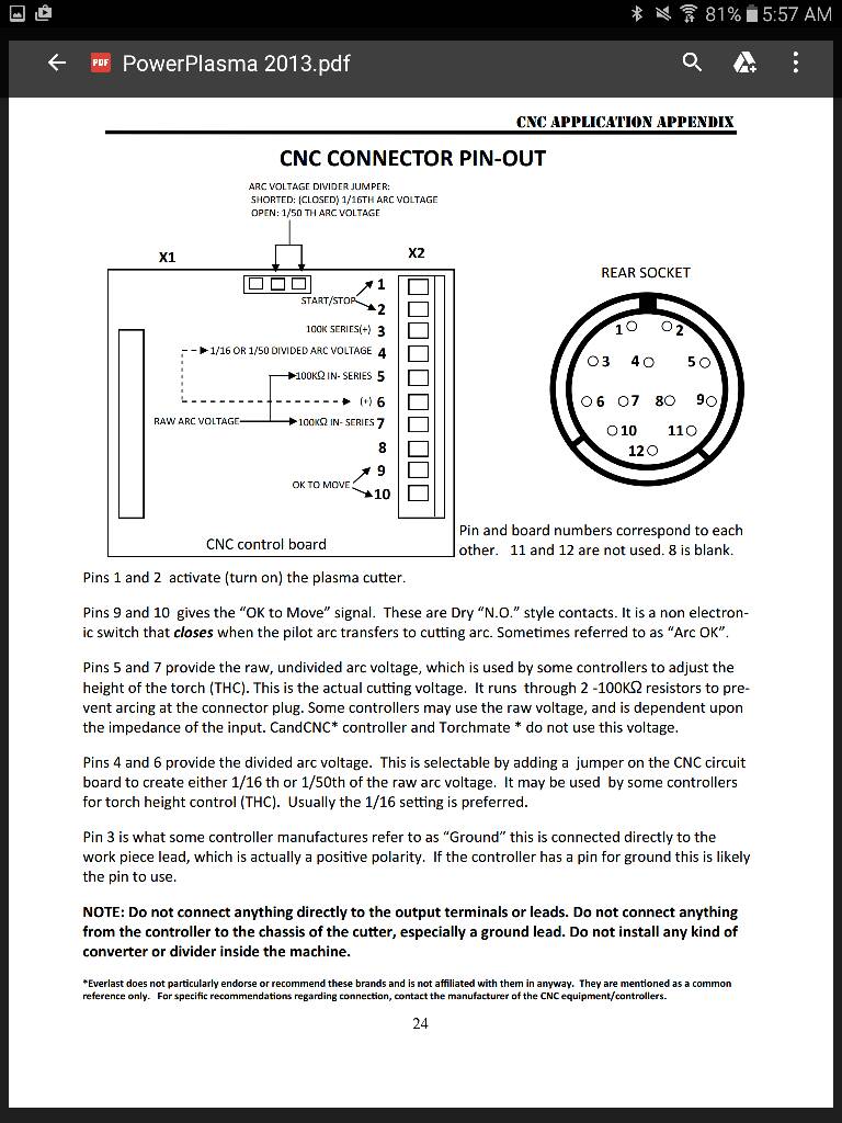
1)*You have the start-stop (Pins 1-2 you short with a relay contact "input" from your controller to start and stop the cutting process)
2)*You have ok-to-move (Pins 9-10 "I am assuming, so test it with an ohm meter" a N.O. output relay contact for the cutter to tell your controller to start running your CNC motors and process).*
The above two are probably all you need for most low cost cutter controllers.
3)*You have the full arc voltage (DC pin 5+ and 7-)
4)*Divided arc voltage (DC 4- and 6+) for higher end machine that require it (1/16 and 1/50 via jump inside the machine).*
There's a jumper inside the machine (on small board in the rear top of the machine that has CNC in big letters and goes to the CNC connector on the back) to set the divided arc voltage. You can have 1/16 of arc voltage (jumper on) or 1/50 of arc voltage (jumper off). It will show this lower percentage of the full arc DC voltage on pins 4- and 6+. Not sure what pin 3 does just yet.*
Other notes
If you have an electronics background and require another divisor, you can "probably" do it with an external voltage divider on arc voltage pins 5+ and 7- or the divided down pins 4- and 6+, with two 1/4 watt resistors. 4 or 7 would be your ground (-), middle of the divider would be the new (+) divided arc voltage.
Before wiring divided arc voltage or anything to your CNC controller, I would take a DVM and check them "if you for some reason chose not to contact your CNC controller vendor".*
If you made your own controller, we hope this helps. We will update this information if we find or hear anything different.
Mike R.
Email:*[email protected]
Inverter Welders, Plasma Cutters, MIG, TIG Welders - Everlast
Inverter Welders, Plasma Cutters, MIG, TIG Welders - Everlast
877-755-9353 x203
M-F 12 - 7PM PST
FYI: PP50, PP80, IMIG-200, IMIG-250P, 210EXT and 255EXT.
-
03-01-2016, 12:10 PM #12
Registered
- Join Date
- Apr 2006
- Posts
- 1016
Re: plasma newbie 101 questions
More info on everlast units
Pins 9 and 10 “OK to Move” are a N.O. contacts, sometimes referred to as “Dry contacts” this is a non electronic switch that closes when the pilot arc transfers to cutting arc. Sometimes referred to as “Arc OK”. Sometimes the controller uses this sometimes not.
Pins 5 and 7 are the undivided arc voltage, used by some controllersto adjust the height of the torch. This is the actual cutting voltage it is run through 2 -100K resistors to prevent arcing at the connector plug. Some controllers can use this as is, Depending on the impedance of the input. CandCNC controller and Torchmate cannot use this as is,most others can.
Pins 4 and 6 are the divided arc voltage this is adjustable by a jumper on the board to either 1/16 or 1/50 the arc voltage, and also used by some controllers for torch height control. CandCNC can use this in 1/16 mode. The 1/50 voltage is hard to detect due to the low voltage and interference from the Hfstart. IE: 200 volts arc voltage would be 4 volts, if the torch voltage dropped 5 volts to 195 the divided voltage would be 3.9. so usually the 1/16 setting is preferred, the default setting is /50.*
Pin 3 is what some controller manufactures refer to as “Ground” this is connected directly to the work piece lead, which is actually a positive voltage. If the controller has a pin for ground this is probably the pin to use.
Tips, don’t connect anything directly to the output terminals or leads. Don’t connect anything from the controller to the chassis of the cutter, especially a ground lead. Don’t install any kind of converter or divider inside the machine. This usualy causes a fire.
Hope this helps, and feel free to call me if you have any questions. If I’m on the phone please leave a message and I’ll call you back. I don’t ordinarily return calls from caller ID with no message, as I don’t want to interrupt someone at work.*
Good Luck.
Last edited by Ray; 05-05-2012 at*06:38 PM.
____
Ray
Everlast Sales and Support Team.
[email protected]
Everlast Alaska
Sent from my SM-T810 using Tapatalk
-
03-01-2016, 01:09 PM #13
Registered
- Join Date
- Apr 2006
- Posts
- 1016
Re: plasma newbie 101 questions
What is a Pilot arc?
There are two types of plasma start up, internal and external ignition. External ignition is when you touch the torch head to the metal and a HV of HF current sparks to ignite (not a good choice for CNC). The internal method know as pilot arc has all the ignition in the torch head, there are two ways of making the spark internal, blowback which is a short to begin with and a spark jumps the gap as the piston opens to create a spark gap, and HF or HV , where the current jumps across a known measured gap internally to ignite the process. This internal or pilot arc start method woud be suitable for CNC.
The life of a consumable is mostly dependant on the operator.
Here is a wikapedia thing which may help also:
The HF Contact type uses a high-frequency, high-voltage spark to ionise the air through the torch head and initiate an arc. These require the torch to be in contact with the job material when starting, and so are not suitable for applications involving computer numerical controled (CNC) cutting.
The Pilot Arc type uses a two cycle approach to producing plasma, avoiding the need for initial contact. First, a high-voltage, low current circuit is used to initialize a very small high-intensity spark within the torch body, thereby generating a small pocket of plasma gas. This is referred to as the pilot arc. The pilot arc has a return electrical path built into the torch head. The pilot arc will maintain itself until it is brought into proximity of the workpiece where it ignites the main plasma cutting arc. Plasma arcs are extremely hot and are in the range of 25,000 °C (45,000 °F).
-
03-01-2016, 02:14 PM #14
Registered
- Join Date
- Apr 2006
- Posts
- 1016
Re: plasma newbie 101 questions
Pros and Cons? Blowback style , (non high frequency start)
By Jim Colt Hypertherm
Blowback style (non high frequency start) torches will transfer an arc to the plate from a fair distance (my Hypertherm Powermax45 will transfer from 1/4" away from the plate). This long transfer distance allows for best plate piercing capability in a mechanized application...by allowing the torch to stay back at a good pierce height which allows the pierce spatter from hitting the torch nozzle orifice....which cause nozzle wear and poor cut quality. The pilot arc also allows for rapid starts on rusty, scaly, or painted materials. Firing the pilot arc in the air will cause nozzle orifice erosion....and should not be done often. I once vivited a user of Hypertherm hand held torches that was doing some cutting inside large storage tanks....it was dark in there and he was using the torch pilot arc as a flashlight. His complaint...short consumable life......we solved his problem by buying him a flashlight.
Non pilot arc torches work well on clean metals, although having to touch start a torch is extremely tough on the torch nozzle (tip), as the arc starts with the nozzle in contact with the plate...and molten metal has no where to go except right back on the nozzle orifice. Once the orifice is no longer perfectly round...cut speeds slow down and cut edge angularity gets worse. Generally....a non pilot torch will not work on a cnc machine...as it is difficult to get the torch to scratch the surface to get the arc started....and, many cnc machines will be adversely affected by the high frequency required to start the torch. It is less expensive to manufacture a non pilot arc plasma system.....and that is the primary reason they are available.
-
03-01-2016, 02:27 PM #15
Registered
- Join Date
- Apr 2006
- Posts
- 1016
Re: plasma newbie 101 questions
Troubleshooting CNC plasma cutting
The plasma cutting process superheats a high-speed column of ionized gas. The plasma jet’s high temperature melts the material being cut, while its velocity removes the molten metal from the bottom of the plate. If ferrous metals are cut with an air or oxygen plasma torch, the oxygen also creates an exothermic boost that helps to provide an oxidizing effect to improve speed and cut quality.
Cut quality is essential in plasma cutting. The four most common cut quality issues for fabricators are dross, edge angularity, material warpage, and metallurgy of the plasma-cut edge. Your ability to achieve the best results depends on the system, torch, and consumables you are using, as well as the accurate control of such highly critical parameters as pierce height, cut height, amperage, gas type and flow rate, and cut speed.
1 Dross
1 Dross is the resolidified metal that adheres to the top and bottom edge of the material being cut (see*Figure 1). Sometimes referred to as slag or a burr, dross is a fairly common problem that has several causes and cures.
Slow cutting speed.*This is the most common cause of bottom dross. Inexperienced plasma machine operators tend to slow things down when they encounter a cut quality issue, but in fact they should do the opposite. Typically there is a speed on a particular material thickness at which low-speed dross appears; as you accelerate to higher speeds, this dross is eliminated. If you accelerate too much, however, high-speed dross can occur. The speed range between low- and high-speed dross is called the dross-free zone (DFZ). The wider the DFZ, the better the cut quality.
Incorrect cut height.*If the torch is too close to the material, bottom dross will appear; if it is too far away, dross or spatter will form at the top of the cut.
Incorrect system power level. The power level needs to be matched appropriately to the material you are cutting. Using too little power in terms of amperage and nozzle selection will result in a nice edge quality, but no DFZ.
Worn-out consumables.*Consumable wear is normal, but it is exacerbated by incorrect piercing and power levels.
Material and surface conditions.*Certain material and surface conditions make the DFZ very narrow or nonexistent. Shot- or sandblasted surfaces on the bottom of the plate provide a rough texture for the dross to adhere to. If your material has a shotblasted finish on one side, make sure that side is facing up during cutting. Rusty, oily, and painted surfaces should face down during cutting to minimize dross. Some steels with high carbon, silicon, or manganese content also will produce a narrow DFZ.
Slow CNC machine acceleration.*If dross is present only in corners and on fine features of the part being cut, your machine might not be maintaining high enough speeds to stay above the low-speed dross limits.

Close proximity of cuts.*If you have a lot of detailed cut lines very close to each other, the material might overheat, causing dross. If your CAM software can apply cut paths based on thermal buildup, use that feature to allow areas to cool before the next nearby cut starts.
So what’s the bottom line on dross? Follow the specs in the plasma torch manufacturer’s manual for the cutting parameters recommended for various materials and thicknesses. The manufacturers design the torches and consumables and spend months in their labs getting the processes dialed in, so they are most likely to have the best answers.
2 Edge Angularity
Edge angularity is generally measured as a positive or negative angle in relation to 90 degrees from the surface of the plate. Keeping in mind that plasma cutters always have some edge angularity, positive, small edge angles generally are most desirable. Negative angles are labeled as undercut.
Plasma process engineers work hard to design minimal angularity into the torch and consumable designs and to ensure that the angularity is consistent around the perimeter of the part. Cutting slowly generally minimizes edge angularity, so plasma system manufacturers typically recommend optimal cut speeds that are the lowest at which you can cut without causing low-speed dross.
Optimum angularity always is achieved at the lowest power level that is specified in your cut charts for the material thickness. If better angularity is absolutely necessary, slow down even more, but you can expect a wider kerf and more dross if you do.
How can you achieve the best edge angularity?
Match the consumables and power level to the material thickness.*Lower power and speed will produce less edge angularity.
Make sure the consumables are in good condition.*A damaged nozzle or shield orifice is the first thing to look for if your edge angle varies dramatically around the perimeter of a cut. The nozzle orifice shapes the arc, so if there is a nick or crater affecting the roundness of the orifice, expect the arc, and consequently the cut, to be affected. The biggest killer of nozzle orifices is incorrect piercing.
Use the correct cut height after the pierce and through the entire cut.*A high-definition plasma cutter needs to stay within 0.005 inch of the recommended cut height; a conventional or air plasma cutter should be within about ± 0.010 in. Make sure the height control is accurate and maintains constant height with no diving.
Consistent and minimal edge angularity can be achieved by using good consumable parts in good condition, employing a good plasma system, and following the manufacturer’s recommended cutting specifications.
3 Material Warpage
Using suggested power and speed levels can help you control material warpage during plasma cutting, to some extent. Higher speeds impart less heat into the material, which generally produces less heat-induced material warpage. Here are some other suggestions:
On very thin materials, use your CAM software to create cut paths that control the heat input by allowing sections to cool before you cut adjacent parts.Use the lowest power level and consumables at the highest possible speed.If you have a water table, minimize dross by keeping water in contact with the material. Keep in mind that on many materials, contact with water can affect edge smoothness and, in some cases, edge hardness (hydrogen embrittlement).Some materials, most commonly cold-rolled, store kinetic stresses in their grain structure. This type of stress often is released regardless of the cutting process.4 Metallurgy of the Cut Edge
All materials cut by plasma will show metallurgical effects on the edges. By choosing the right gas mixes and process power levels, you usually can minimize these effects. Often the edge metallurgy is affected by the localized high temperature of the cutting process, but atmospheric gases around the cut edge also have an effect.
Oxygen plasma produces the best edge metallurgy on most carbon steels. Some systems use an oxygen plasma/oxygen shield gas for cutting holes less than 2.5 inches in diameter. This produces hole edges that are almost unaffected by the cutting process and, in fact, often suitable for thread tapping. Oxygen-cut edges are 100 percent weldable and machinable, and they tend not to crack during forming operations.
Air plasma or nitrogen plasma will cause some edge hardening and nitriding on most steels. The nitriding can make the edges brittle and create porosity in some welding processes. Generally, the nitride layer is 0.006 to 0.010 in. thick and thus easy to remove.
Most abrasion-resistant wear plate will show some slight softening, usually less than 0.010 in. from the edge, with both air and oxygen plasma cutters. Stainless steel less than 0.250 in. thick will cut with a very pure edge using a mix of 5 percent hydrogen/95 percent nitrogen as a plasma gas and nitrogen as a shield gas. Thicker stainless sections will have a pure, weldable edge when cut using a 35 percent hydrogen/65 percent argon mix with a nitrogen shield gas. In addition, if you cut stainless steel under water using nitrogen plasma and nitrogen shield gases, you can eliminate the oxide layer that forms when cutting in ambient air.
Before trying any gas combination that your equipment might not be designed for, however, contact the manufacturer of your plasma cutting equipment. Incorrect gas combinations certainly can damage equipment and cause
-
03-01-2016, 08:30 PM #16
Registered
- Join Date
- Apr 2006
- Posts
- 1016
Re: plasma newbie 101 questions
More info on cut quality and trouble shooting tips

-
03-02-2016, 09:44 AM #17
Registered
- Join Date
- Apr 2006
- Posts
- 1016
Re: plasma newbie 101 questions
some info on typical grounding method for plasma cnc tables and electronics
-
03-04-2016, 07:56 AM #18
Registered
- Join Date
- Apr 2006
- Posts
- 1016
Re: plasma newbie 101 questions
-
03-05-2016, 10:59 AM #19
Registered
- Join Date
- Apr 2006
- Posts
- 1016
Re: plasma newbie 101 questions
Attach is electrical schematic for neuron.cnc thc

Disclaimer use at your own risk... for informational purpose only.
Note this configuration is "custom hardware set" for 16:1 arc input voltage on the voltage diver brd.
ie for most everlast plasma units
The voltage divider pin outs are shown / labeled for only the everlast cnc port only!
**Warning*** Other plasma units may have different pinouts on there cncports....
As seen in above manual for everlast user manual.( PowerPlasma 2013.pdf)
The plasma supply interface brd ( voltage divider) default set to 20:1 as noted on the silk screen on schematic.
Contact neuron.cnc if you require assistance for voltage divider questions
__________________________________________________ _________________________________________
Next schematic shows Bob connections and ess light ver of neuron brd

Disclaimer use at your own risk... for informational purpose only.
Note the above schematic doesn't show the plasma supply interface brd ( voltage divider)
How ever it would be connected the same way as the frist schematic.
Andrew at neuron is always very knowable and helpful with questions.
Neuron CNC
-
03-05-2016, 12:01 PM #20
Registered
- Join Date
- Apr 2006
- Posts
- 1016
Re: plasma newbie 101 questions
Powermax plasma
Voltage divider Schematic for power max units only.. for Neuron thc.

Disclaimer use at your own risk... for informational purpose only.

 Reply With Quote
Similar Threads
-
Newbie Questions
By tgdavies in forum Chinese MachinesReplies: 2Last Post: 08-07-2013, 02:01 PM -
Mechanical Questions From a Newbie CNC Plasma Table Builder
By CNC-Dude in forum Plasma, EDM / Other similar machine Project LogReplies: 1Last Post: 01-15-2011, 05:25 AM -
Some Newbie Plasma CNC Questions
By vacextar in forum Waterjet General TopicsReplies: 1Last Post: 01-12-2011, 03:31 PM -
Newbie with questions on DIY plasma table controls
By mpascino in forum Waterjet General TopicsReplies: 7Last Post: 11-23-2009, 03:48 PM -
Newbie Questions
By Jzbass25 in forum Open Source CNC Machine DesignsReplies: 7Last Post: 04-26-2007, 04:10 AM
