


Bought a G0704 a few months ago... In the process of doing a CNC conversion on it.
The plan.
- hiwin linear rails on Z axis
- 2 inch head & column spacer
- 1hp 3 phase 56c motor
- belt drive
- double nut ball screws
- oil system for ways
- grease system for screws
-power draw-bar (air over hydraulic)
- flood coolant
Electronics.
- Mach 4
- intel NUC
- ESS smoothstepper
- mx3660 driver
- 48v 12.5amp power supply
- nema 23 570oz stepper (x/y)
- nema 34 906oz stepper (z)
- hitachi VFD (modbus)
Fresh off the boat....
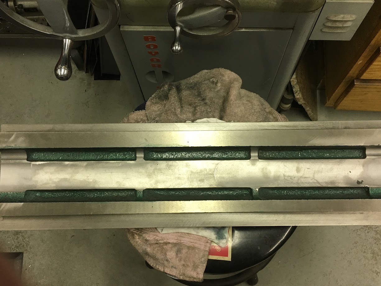
The hiwin linear rails where the first task to be tackled. 15mm CA preload. Milled off the dovetails in the kneemill. Turned out really great.....
Milling the Z axis slide for the linear rail "cars"

Thread: THE GRIZZ
Results 1 to 20 of 726
Hybrid View
-
12-10-2016, 01:48 AM #1
 Member
- Join Date
- Oct 2013
- Posts
- 543
THE GRIZZ
-
12-10-2016, 02:01 AM #2
Member
- Join Date
- Oct 2013
- Posts
- 543
Re: THE GRIZZ
Z axis slide milled and drilled for the linear rail cars.
Now comes the head spacer. Started with a hunk of 2 inch mic-6 aluminum.
After some milling... pay no attention the minor mess up lol (started to bore hole in the wrong place!) we where able to recover nicely in the end!
gettin there...
there we are!!!
-
12-10-2016, 02:17 AM #3
Member
- Join Date
- Oct 2013
- Posts
- 543
Re: THE GRIZZ
Column spacer.... started off with a big chunk of steel. used an equally large face mill to get it to size and then off to the surface grinder it went. The column spacer is keyed to the base of the milling machine and has 2 additional cap screws to hold it in place while putting the main column bolts in.
setting up the base to mill key slot.
-
12-10-2016, 02:20 AM #4
Member
- Join Date
- Oct 2013
- Posts
- 543
Re: THE GRIZZ
key slot cut and two spacer block retaining bolts drilled and tapped
bolted on to the base.
-
12-10-2016, 02:31 AM #5
Member
- Join Date
- Oct 2013
- Posts
- 543
Re: THE GRIZZ
some other random tidbits.
turned off the gear portion of the quill drive "barrel" (more on this when its time to make the belt drive)
set screw holes that lock the quill from moving.
made a wrench for one of the spindle bearings.
some new extended head bolts. turned the heads of the bolts down. ground some flats on some thick washers, and brazed them together.
-
12-10-2016, 02:42 AM #6
Member
- Join Date
- Oct 2013
- Posts
- 543
Re: THE GRIZZ
Today i made some headway on the x & y ball-nut grease setup. it has been a struggle to fit everything nicely under the table and not have it look like a drunken madman attacked it with miles of tubing. one grease zerk on the side of the saddle feeds both x and y ball-nuts. There will be a separate system attached to a "one shot" oilier for the ways....
cleaned up the underside of the table and made some clearence for one of the fittings feeding the ball nuts.
-
12-10-2016, 03:22 AM #7
Member
- Join Date
- Oct 2013
- Posts
- 543
Re: THE GRIZZ
Purchased a 4in "cnc" vise.... i believe it was a shars. Overall i was happy with the quality, the one thing that really bothered me was how horrible the screw fit in the base of the vise. When it was all said and done i i added a thrust bearing to the outside, made a new collar / bearing holder and bushed the shaft part of the screw... also moved the grease zerk to the front of the vise. It was a fun little project. Now i have a semi nice feeling Chinese vise! haha
-
12-10-2016, 03:34 AM #8
Member
- Join Date
- Oct 2013
- Posts
- 543
Re: THE GRIZZ
just recieved my VFD in the mail today. Does anyone know if i will need any specific hardware to interface between the VFD and MACH? thanks!!
-
12-10-2016, 08:27 PM #9
 Member
- Join Date
- May 2008
- Posts
- 1185
Re: THE GRIZZ
Really nice work on the 704.
Generally the Z is fairly good on the 704 with the head being light and the Z slide being nice and long but you made fitting the rails look like a two hour project and they fit quite nice. Super clean.
Did the oil fitting on the X clear the table, Its so tight under there?youtube videos of the G0704 under the name arizonavideo99
-
12-10-2016, 09:04 PM #10
Member
- Join Date
- Oct 2013
- Posts
- 543
Re: THE GRIZZ
Dave,
You're right..space is really limited in the X axis under the table. I had to get really creative with the fitting size and position to get them to fit..even with that, you can see in post #6 that I had to relieve the underside to the table a hair. It would be cool if the rotational position of the X axis nut was skewed one hole over so the oil hole would lay down a bit more which would make for a more compact arrangement.
I built a new Y axis nut retainer that has a oil hole and o-ring arrangement to be able to mount the fitting in a different location. It is also pictured in post #6.
Getting the lubrication plumbing to be functional and yet look clean isn't a 5 minute job..I still have all the plumbing for the ways to figure out.
The ball nuts are tapped for M6 X 1.0...this couldn't be a more difficult thread configuration to find fittings for and the hardness of the ball nut precludes any modification..as least by me!
I will add this. The ball screw assemblies came from Dave at 'arizonavideo' and he bent over backwards to make sure everything was just as ordered. A true gentleman.
Stuart Miller
-
12-11-2016, 05:27 AM #11
Member
- Join Date
- May 2008
- Posts
- 1185
Re: THE GRIZZ
To rotate the X nut would help to leave room for the Zerk but the mounting would have to change requiring to mill and tap the Y slide.
For oil I was thinking a plastic tube of the right size to tap to M6 and then put a wire in it to prevent it from kinking then use a heat gut to make a sharp bend.
What is your plan for the belt drive?youtube videos of the G0704 under the name arizonavideo99
-
12-11-2016, 06:14 AM #12
Member
- Join Date
- Oct 2013
- Posts
- 543
Re: THE GRIZZ
For the belt drive..I ordered a J section, 4 rib poly belt just to see what it looked like in person. It's the right scale for the machine and will handle the HP just fine. I have read the poly sheaves are easy to make so I'm going to give that a go. The spindle sheave will be a tap fit onto the OD of the splined shaft on the spindle and will also fit down into the ID of that large upper bearing. This plan seems like it will stabilize the upper end of that long splined shaft, giving it more rigidity.
The driven pulley OD will be based on the available room for the driver OD pulley, and such that it give me a ratio of around 1.44:1..but also allows me a center distance for a off the shelf belt.
These are my plans..we'll see what reality brings! The timing belt drive was my first choice but my son has read there is more noise associated with it and above all, I'll like this little Chinese bucket of bolts to run smoothly and quietly.
Stuart
-
02-13-2017, 02:48 AM #13
Member
- Join Date
- Oct 2013
- Posts
- 543
Re: THE GRIZZ
No pictures today, but an update nonetheless. I started making the 'top hat' for the power draw bar today and things went sour in a hurry. The top of the spindle on these machines is threaded 20mm X 1.0. My design called for my top hat to screw onto these threads which would also secure the poly belt pulley to the spindle. After hours of fussing it finally became apparent that the factory threads were cut slightly out of line with the spindle axis. How this happened is beyond me! This wouldn't allow the top hat to seat flat on the pulley and also resulted in about .015 of lateral run out.
As Nick (my son) stated..if nothing else is done right on this conversion, the spindle has to be perfect. It must be balanced, true and quiet. The Chinese thread job was not going to let that happen.
So...3/4" X 16 TPI is real close to the existing size, but not much would be left of the threads if I merely threaded over the existing ones. My plan is to tig weld up the threaded portion, then single point it 'dead nuts' in the lathe with the new 3/4" X 16 thread.
I'll take my camera down to the shop and get some pictures of this when I do it.
Stuart
-
02-15-2017, 01:03 AM #14
Member
- Join Date
- Oct 2013
- Posts
- 543
Re: THE GRIZZ
I had success re-treading the end of the spindle!!! It was quite the task setting up the spindle in the lathe and dialing everything in perfect. 3/4 - 16 threads were single pointed after the spindle was setup in the lathe. Now time to proceed with the top hat portion that will thread onto the newly corrected spindle threads. Also picked up some 4140 for the clamping part of the power draw-bar as was as the draw-bar its self!
(newly "minted" threads!!!)
(top hat in progress)
(top hat progressing....)
(soon to be "clampy" part of draw-bar)
(the thing that says draw-bar on it....)
Thanks!!!
-
02-15-2017, 04:18 AM #15
Registered
- Join Date
- Nov 2012
- Posts
- 220
Re: THE GRIZZ
Hey man,
I feel certain the thread on top of your spindle was M20X1 (metric) and not 3/4-16, so it might not have been messed up...
-
02-15-2017, 05:23 AM #16
Member
- Join Date
- Oct 2013
- Posts
- 543
Re: THE GRIZZ
You are absolutely correct...the thread on the spindle WAS 20mm X 1.0...but any more. The factory thread was somehow cut out of parallel (?) with the axis of the spindle and would not allow a threaded piece to sit flat on my poly pulley. I dialed the spindle in on the lathe and cut a new thread...3/4" X 16 and now everything is square, plumb and proper. Originally Posted by gcofieldd

How those factory threads were cut out of whack is beyond me. I machined a disc and single pointed internal 20mmX1.0 threads in it, screwed it onto the spindle...it wobbled like a drunken sailor.
Stuart
-
12-11-2016, 10:00 PM #17
Member
- Join Date
- May 2008
- Posts
- 1185
Re: THE GRIZZ
I ground a tool to cut the J belt groves. I think is was 23deg angle. The stock profile has a flat bottom but this made the cutter wonder when you started to cut so I changed to a point.
I have done a bunch of pulleys.
http://s1294.photobucket.com/user/ar...64043.jpg.htmlyoutube videos of the G0704 under the name arizonavideo99
-
12-11-2016, 10:32 PM #18
Member
- Join Date
- Oct 2013
- Posts
- 543
Re: THE GRIZZ
Dave,
Wow....those look absolutely beautiful, and the tensioning method is very clean. It isn't "Grizz" though, is it...a little larger machine with some elbow room, still very nice. I'll keep the form tool shape in mind when I start to make some pulleys, thanks.
Stuart
-
12-12-2016, 02:28 AM #19
Member
- Join Date
- Oct 2013
- Posts
- 543
Re: THE GRIZZ
Here are some photos showing the X & Y lubrication clearance under the table. The rough cast corner radius of the underside of the table was cleaned up with a ball endmill. One of the criteria for the screw and way lubrication system was that it had to look clean and not like a after thought..... hopefully all the hard work will pay off!
The photos below show how the Y nut mount incorporates a passage for the grease to pass through into the nut. I put a chamfer on the Y nut with a carbide spade drill that a o-ring sits in... to seal between the nut and nut mount.
top view of Y nut mount (showing where lube comes in...)
(hole through Y mount)
Chamfer in Y nut for o-ring to live
O-ring sitting in chamfer
Y nut and mount...
Y nut and mount in final position..
and finally some closer shots of the X & Y fittings and lines (put a Y push to connect fitting in there in order to feed both nuts via one zerk)
-
12-14-2016, 02:25 AM #20
Member
- Join Date
- Oct 2013
- Posts
- 543
 Re: THE GRIZZ
Did some brain storming on the oiling system for the ways of the mill today. I belive we have a game plan now.... involving some manifold, holes and some copper tubing. Made a fitting out of some brass, counterbored 6/32 cap screw to hold it on to the side of the saddle, the copper tube will be soldered to the fitting and a o-ring and short section of tubing willl go into the saddle...
started with a chunk of brass.
machine a little..
and "bobs your uncle".
More to come soon!


 Reply With Quote


Similar Threads
-
enough yapping---grizz x3 //ordered// RECEIVED
By project5k in forum Benchtop MachinesReplies: 95Last Post: 01-09-2008, 11:50 AM
