


Hello all
I have a unipolar Sanyo Denki DC stepper with the following rating
Volt : 5.5v Current: 1.5A
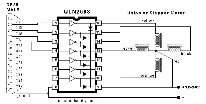
Looking for Stepper drivers i came across ULN2003 chip which allowed me to run the motor with minimum circuitry through the parallel port on my PC( I'm not an electronics person, hence searched for the simplest option out there).
But the problem is the current output from ULN2003 is only 500mA.. and hence the torque from the motor is very low ( i can stop it very easily using my hand)
I searched for current amplification components n circuits but it all sounded a bit Greek to me...
So if somebody can guide me how to go about it..i will really appreciate it.
(if its of any help i came across this chip LMD18200 with current output of 3A...if its possible to drive the motor with any such chip that wud be wonderful)
Thx
Results 1 to 11 of 11
-
02-16-2007, 07:53 AM #1
 Registered
- Join Date
- Jan 2007
- Posts
- 15
Query: Current amplification for driving stepper motor...
-
02-16-2007, 05:36 PM #2
Gold Member

- Join Date
- Jun 2003
- Posts
- 3312
take a look at some of the driver circuits on my website. http://PMinMO.com maybe something there that will help you.
Phil, Still too many interests, too many projects, and not enough time!!!!!!!!
Vist my websites - http://pminmo.com & http://millpcbs.com
-
02-18-2007, 10:00 AM #3
Registered
- Join Date
- Jan 2007
- Posts
- 15
hey thx for ur post....
i did find some useful stuff at ur site...Good work done!!
but still if anyone can guide me how to use mosfets to amplify current from the ULN2003 ...It'll help me make use of Mosfets in the future on my own...
C'mon all u geniuses..pls help me out...
I am attaching the schematic of the circuit im using
-
02-18-2007, 10:12 AM #4
Registered
- Join Date
- Mar 2004
- Posts
- 1147
your design uses the parallel port to control each phase of the stepper. this is bound to be very slow! with 3 axis doing this, you are probably going to have trouble.
if you want to use mosfets, you do not need the buffer chip. a better choice would be to look for a dedicated stepper driver chip to power the mosfets, or darlington transistors, as they may prove more practical.
unless your budget is very small, i would recommend looking at a better drive system. even a discrete driver using logic ICs to do 'full stepping' will be significantly better than your current intentions..
i used what you have on a 2D plotter device, and it sorta worked... You need o add in some more components to make just mosfets work relialably. i believe you will also need 1,2, or more ceramic 'power resistors', a large capacitor.... etc.
the price difference to use a better drive system could be around $5 per axis... totally worth the effort.
-robert
-
02-18-2007, 04:44 PM #5
Gold Member
- Join Date
- Jun 2003
- Posts
- 3312
Invert your logic and use a mosfet:
Phil, Still too many interests, too many projects, and not enough time!!!!!!!!
Vist my websites - http://pminmo.com & http://millpcbs.com
-
02-18-2007, 07:07 PM #6
Registered
- Join Date
- Jan 2007
- Posts
- 15
Hi Originally Posted by vacpress

At the very ouset I'll take the opportunity to thank u for ur response...
Abt th design.. frankly i chose this one just because im a rookie in the field of electronics and at that time all i inetended to do was to check whether my motor was working or not.
I have no problems in putting more money if i makes my system more reliable.
U mentioned "Stepper Driver Chips", but when i search with that keyword i generally gets results like the ULN2803, ULN2003 and similar....
I did find a few driver circuits at http://pminmo.com/ but as i said I'm a rookie and these circuits were a bit complex...
Anyway, Im open to suggestions regarding what chips to use and to couple them with Mosfets or other devices...
(Also if im not going to use the Parallel port what r my options...Microconntrollers i guess..)
Please put in ur advice...by the way what do u think abt the
LMD18200 as a stepper driver chip or the UCN 5804...
Looking forward to some more gr8 responses.
Thx again
-
02-19-2007, 11:32 PM #7
Gold Member
- Join Date
- Jan 2006
- Posts
- 2985
I think this is a decent route to take.
http://www.aaroncake.net/circuits/stepper.htm
It is very similar to pminmo's discrete board. You should have another look at it. It really isn't difficult at all if you pay attention and follow the instructions.
http://pminmo.com/discrete/discrete.htm
Good Luck
Matt
-
02-20-2007, 03:38 PM #8
Registered
- Join Date
- Jan 2007
- Posts
- 15
hey thx for the links....
I was looking for other chips myself ( and simple looking schematics) and came across this one...

i can see this is an easy to build circuit but then again...how ami supposed to pulse the step pin again n again to make the motor run...
any comments ??
-
02-20-2007, 10:50 PM #9
Gold Member
- Join Date
- Jan 2006
- Posts
- 2985
well I would assume you could use the parallel port to provide the step pulses, just as you had planned at the start of the thread. If you want a standalone system then look at the step pulse generator thread also in this forum.
Matt
-
02-24-2007, 05:13 AM #10
Registered
- Join Date
- Jan 2007
- Posts
- 15
Hi again...
I looked for the chip 5804 and it seems these r not easily available in this part of the world (india)...
So, in my desperation to get things moving i bought a few more ULN2003s since i had a faint recollection abt somebody telling me to connect these in parallel to get the required current.... I know this isnt the best option but if this doesnt work out for me..
I'll try to put together the discrete board mentioned by Keebler...
but yes i had this question in my mind...if im using an adaptor with a current limit of 500mA to power the circuit is it possible to get 1.5A current even after connecting 4 ULNs in parallel...??
(i have posted the schematic in an earlier post)
-
02-24-2007, 05:09 PM #11
Gold Member
- Join Date
- Aug 2006
- Posts
- 2758
Originally Posted by junior85
You won't get more current than the maximum your power supply is able to deliver without dropping the power supply voltage and probably destroying it.
You want to get 3 times more current than the one your PS is designed for, get another power supply.

 Reply With Quote
Similar Threads
-
Stepper motor: voltage vs. current ratings
By cnczane in forum DIY CNC Router Table MachinesReplies: 3Last Post: 09-08-2008, 06:14 PM -
Driving one axis with two stepper motors?
By stevesplanes in forum Linear and Rotary MotionReplies: 15Last Post: 05-09-2007, 09:03 PM -
Back driving a stepper
By cncuser1 in forum Stepper Motors / DrivesReplies: 5Last Post: 06-16-2006, 06:18 AM -
driving motors at what current?
By 900steve in forum CNC Machine Related ElectronicsReplies: 8Last Post: 10-26-2005, 03:53 PM -
Stepper motor current
By alanhunt in forum CNC Machine Related ElectronicsReplies: 3Last Post: 12-18-2003, 04:58 PM
