


Hi All
I'd like to build a metalworking CNC router for materials such as: hard and mild steels, high-quality steels, stainless steels, and others of the sort. The easiest route for me is to build the machine out of bosch rexroth aluminum profiles, but I'm worried about flexing and vibrations.
My question is: before I throw the effort to research and calculate the base, gantry etc..., is it at all possible to have a dissent metalworking CNC router built out of aluminum profiles?
the work volume is 500x400x250mm, while the machine dimensions would be in order of 1500x1500x1500mm (large spacings between bearings to mitigate the moments created by the cutting action). I'll work steel plates no thicker than 15mm. I'll use end mills of 8mm max. I'll use 6.5kW spindle.
4mm and 6mm end mills would be the typical tools, the 8mm and 10mm end mills would be for facing operations only, not deeper than 0.5-1mm.
If I use beefy 80x80mm rexroth profiles and 80x160mm in more critical areas; If I maximize the distance between the linear bearings to 1.5 or even 2 times the z axis travel or more, and put intermediate bearings, or even additional rails/bearings per side would that mitigate the fact that I use aluminum profiles.
I plan to build a really beefy base, gantry and plunger, with many cross beams and reinforcing beams where possible. My budget is quite large...
Also I don't pursue fast and efficient process. Having the machine work for 6-8 hours on a piece is fine with me. (I mean the machine would not endure the thick chip load, professional machines usually do).
I'm going to put two pre-loaded nuts per screw to get rid of back-lash, also tightened linear bearings, and pre-loaded cone-ball bearings for the screws.
I also consider the possibility of building the machine out of reinforced foam-concrete. I heard it has great vibration dampening properties. But that is considerably more difficult option for me.
Thanks a lot, in advance.
Results 1 to 20 of 47
-
09-16-2017, 12:35 PM #1
 Member
- Join Date
- Feb 2017
- Posts
- 32
Is it at all possible to build a metalworking CNC router out of aluminum profiles.
-
09-16-2017, 08:24 PM #2
Member
- Join Date
- Apr 2004
- Posts
- 5734
Re: Is it at all possible to build a metalworking CNC router out of aluminum profiles
No, that's not going to work too well. Routers in general are intended for materials up to aluminum in hardness. They are different from milling machines, which are designed to cut steel. Milling machines need to be a lot more massive; aluminum extrusions are too light. Particularly for materials like stainless steel, you can't just take lighter cuts to compensate for a flimsier machine; they need a fairly heavy cut to avoid work-hardening.
I'm not familiar with the foam-concrete material you mention, but I have heard of successful steel-cutting machines built with monolithic epoxy-granite castings. But the most cost-effective way to get a machine that will do what you want is usually to find an older cast-iron mill, preferably one that was previously used as a CNC machine, with ball screws, motor mounts, and an operational spindle. Often these can be bought cheaply with a dead or obsolete controller, so that all you need to do is haul it away and retrofit the motion-control system with something that works.
-
09-16-2017, 08:42 PM #3
Member
- Join Date
- Feb 2017
- Posts
- 32
Re: Is it at all possible to build a metalworking CNC router out of aluminum profiles
So that's why I've never seen a metalworking CNC router at all... Even a factory manufactured one. So I'm guessing that even if a router is build out of heavy steel or cast iron it would still not work properly. Am I right?
-
09-17-2017, 02:39 AM #4
Member
- Join Date
- May 2011
- Posts
- 790
Re: Is it at all possible to build a metalworking CNC router out of aluminum profiles
I wouldn't say that necessarily. Originally Posted by Ivan-Ivanov

Many of the VMC's that cut steel really well, like Mori for example, essentially those are "routers". Just at a different level. The gantry moves on many of those machines.
Sure, you could build one out of aluminum. Big solid aluminum blocks or castings, you could have a dandy machine to cut steel with. Of course, steel is 3x stiffer than aluminum, so you would need more aluminum by volume than steel to get the same stiffness. Bigger box sections, etc. Whether you can accomplish this using the largest T slot sections or not, I don't know, but my guess is that they aren't a good choice. Thick aluminum plate, or solid aluminum extrusions, and all thought out and designed meticulously well before hand, yes, it can be done. There's no reason why not. If you could get your hands on a FEA program, that could be a big help so long as you use the input parameters correctly.
I won't go as far as to say it's impossible though. But in all the T slot aluminum builds I've looked at, I've never seen anyone pull it off. It would have to use much bigger sections than are typically used.
For the spindle 6.5 kw should be more than enough power, but you would need power available at the lower RPMs that you would cut steel at. The bits you want to use are small in diameter, so perhaps the spindle would be OK, I can't tell you that off hand.
How big are the parts you want to cut? The best idea is to use a plasma cutting machine to cut large sheet in 2D and buy a bridgeport mill and retrofit it to machine smaller parts in 3D.
What you are talking about will cost much more money than a typical router, and will need to be very stiff, and easy to mess up in the design process. But not impossible.
500mm is just shy of 20 inches. So if you want a cutting area length of 30 inches max lets say on your longest axis, you are not describing a CNC router, you are describing a DIY VMC machine. If you can find a good used machine that will accommodate the travels you want, you may be better off, this project will be alot of work.
Hmmm, you never said T Slot. You just said profiles. That could be anything. OK, yes it is possible but you need to know what you're doing and spend alot of time on the design first. And it won't be cheap.
-
09-17-2017, 04:02 AM #5
Gold Member
- Join Date
- May 2005
- Posts
- 3920
Re: Is it at all possible to build a metalworking CNC router out of aluminum profiles
awerby covered most of the issues with an Aluminum extrusion machine, it won't work for anything that I would call machining. You might be able to do engraving but honestly I don't recommend Aluminum extrusions if other techniques are possible even for machines targeting wood working and aluminum. Originally Posted by Ivan-Ivanov
I wonder if you have much experience machining Stainless Steels as trying to do that on a router would lead to heart ache. As pointed out many grades of stainless work harden and are frankly a real ***** to machine even on a milling machine. If this is a goal, along with machining hard steels, tool steels, you will want a fairly complete milling machine setup, that includes a flood coolant solution, 360 degree guarding and a spindle with a low speed capability (compared to a router spindle).
Now to your specific question here, there are mills that are very similar to routers, often referred to as gantry mills or planer mills. Often these sorts of mills are massive, there are videos on line of gantry mils, milling the castings for a milling machine ( I believe there is one of a Haas factory). However there is nothing that says they have to be massive You could build such a mill out of steel for example, to cover the working dimensions you suggested in your first post. You would be doing this with very large steel tubing and ideally access to a good machine shop. You could even do cast iron but that would require even more outside help.
So what you would need is to design a very rigid structure, find a suitable spindle and come up with the controls. The spindle and controls would be relatively easy, a rigid mechanical design a lot harder but a gantry design is advantageous when it comes to rigidity. Consider this, the common Bridgeport mill is considered to be a very light duty mill in industry yet it is a very heavy machine compared to any router discussed in this forum. Even then some would say that a Bridgeport isn't rigid enough. If you want something to read with respect to machine design using steel try looking for: Principles of Rapid Machine Design, a paper written by a guy named Bamberg. It gets a little deep but some concepts come out after a bit of reading. One point is that steel alone probably isn't good enough as it can have issues with resonance thus the need to control that with various infill methods.
In the end building a milling machine suitable for steel often ends up more expensive than the common approach. That approach into buy the cast-iron form China and retro fit the iron as a CNC machine. Tool suppliers like Grizzly, Little Machine Shop and a whole bunch of others import Chines milling machines in various sizes that people uses as donor machine to make a CNC mill from. The results are highly variable with a low depending upon the builders skills, his access to a machine shop and the money invested. As others have suggested sometimes you are better off looking of a commercial mill that has a crapped out controller that can be had for scrap metal prices. The good thing here is that your working dimensions are not that bad so it can be handled by a fairly small mill. One thing that is certain is that Chinese iron is often cheaper than trying to buy raw materials in the USA.
So in a nut shell, yes you can build a milling machine that looks something like a router that will be capable of milling steels. The problem is that undertaking is likely to be far more involved than you realize. At the minimal you would need access to heavy walled steel tubing and the equipment to machine it, weld it, heat treat it & etc. It is a lot of work that if you have to pay for by the hour gets to be very expensive. Also I assume that you are looking for readable precision which means you have to put a lot of effort into machining, setup and assembly.
-
09-17-2017, 04:11 AM #6
Gold Member
- Join Date
- May 2005
- Posts
- 3920
Re: Is it at all possible to build a metalworking CNC router out of aluminum profiles
One could go the Gingery route and cast everything himself. I'm not sure if the original poster is familiar with Gingery's books but the concepts could be extended for a machine large enough to do what the original poster wants. I however wouldn't suggest going that route unless one has a really cheap source of aluminum and some help as the casting sowed have to be huge. Originally Posted by NIC 77
As for commercial T-slot extrusion there is no way I'd suggest using them for what the poster wants to do. But back to casting, considering that the castings would be huge, thus requiring team work; it would make more sense to have the castings done in iron at a local iron foundry.
"It won't be cheap" is the operative phrase here. Nothing is impossible but a well designed machine that can reasonably handle the materials he wants to handle won't be cheap to do.I won't go as far as to say it's impossible though. But in all the T slot aluminum builds I've looked at, I've never seen anyone pull it off. It would have to use much bigger sections than are typically used.
For the spindle 6.5 kw should be more than enough power, but you would need power available at the lower RPMs that you would cut steel at. The bits you want to use are small in diameter, so perhaps the spindle would be OK, I can't tell you that off hand.
How big are the parts you want to cut? The best idea is to use a plasma cutting machine to cut large sheet in 2D and buy a bridgeport mill and retrofit it to machine smaller parts in 3D.
What you are talking about will cost much more money than a typical router, and will need to be very stiff, and easy to mess up in the design process. But not impossible.
500mm is just shy of 20 inches. So if you want a cutting area length of 30 inches max lets say on your longest axis, you are not describing a CNC router, you are describing a DIY VMC machine. If you can find a good used machine that will accommodate the travels you want, you may be better off, this project will be alot of work.
Hmmm, you never said T Slot. You just said profiles. That could be anything. OK, yes it is possible but you need to know what you're doing and spend alot of time on the design first. And it won't be cheap.
-
09-17-2017, 09:18 AM #7
Member
- Join Date
- Sep 2006
- Posts
- 6463
Re: Is it at all possible to build a metalworking CNC router out of aluminum profiles
Nope............for what you want a CNC router is really not the way to go.
You could build it as a moving table type as that allows you to have a massive well braced structure to resist the cutter forces......but I would suggest that option is in steel tube with a thick wall section.......welding is the way to go in that respect.
Building with a moving table of 500 X 400 means you have the 500 dimension across the X axis to reduce the overall length of the machine.
Moving table types are usually twice the Y axis table travel length to get the full spindle table coverage of 400mm.....but by clever spacing of the Y axis bearing blocks along the rails at 300 mm overall you can get the overall length down to 600mm.
Overall width does become wider at 500mm for the table plus side clearance between the upright supports of 20mm per side and uprights of at least 100mm thick in a box section etc. to give you a width of approx. 750mm +.....height just falls in with the design once you lay it out.
Attached is a pic of 2 commercial machines on those lines for appreciation of what direction you need to look at as a DIY concept.......the layout would follow the lines but in whatever material and method you choose to build with.
BTW.....I would go for a spindle and separate belt driven motor to get the all important low rpm torque that you will want to have for milling steel as opposed to the high speed lighter wood carving router designs......you can also have a change over water cooled spindle option to do high speed carving work.
Ian.
-
09-17-2017, 10:43 PM #8
Member
- Join Date
- Feb 2017
- Posts
- 32
Re: Is it at all possible to build a metalworking CNC router out of aluminum profiles
Hello again.
Thank you all for your replies. As you already noticed by the language I use that I have no experience in building CNC routers or machining. (I didn't even know those aluminum profiles are called T-Slots (facepalm) XD) I'm a programmer by trade. At this point I think I'm still in the low knowledge, low experience, high enthusiasm phase.
I've build one CNC router so far, but without a proper design process. I just chose the T-slots I "felt" would be right. Then guides and linear bearings, screws, nuts and the rest of the elements forming the linear motion system, picked them all by intuition. I made a design in SolidWorks, and assembled the thing (after work and on the weekends, took me about 1 year). Of course it didn't work properly at first, but after reworking some fo the parts, now it cuts well 10mm aluminum plates with precision of 0.05mm... Former 0.5mm (facepalm). I fixed that by putting new screws with anti-back lash nuts and two pre-loaded cone-ball bearings in the bearing housing of every screw (I use the fixed-supported type for the screw bearings). I even fitted it with a flood cooling system... It's pretty slow however, it takes hours to cut a piece of about 200x200mm with several wholes in it. If there are pockets involoved, the time it takes jumps even more.
Yes I knew that from the start. However I wanted to build it myself because I love the process and wanted gain experience. Also, probably propelled by my ignorance I thought it would be manageable for me, but after reading all the posts here, the used/chinese cast iron mill route looks much more appealing to me. Originally Posted by awerby
I actually meant T-Slots, I just didn't they are called that XD. Originally Posted by NIC 77
About the stainless seel. OK that was an exaggeration. As I listed the materials, it kind of felt right at the time to complete the list by mentioning the stainless at the end, but it somewhat diverted the conversation. My mistake.
The hardest material I actually plan to cut is: "seel 45" here is description if you aren't familiar with this notation: 45 / 45 High quality structural carbon steel
(in case the link can't be opened)Grade : 45 ( 45 ) Substitute: 40Х, 50, 50Г2 Classification : High quality structural carbon steel
About the spindle. Some of you mentioned that using a spindle with a belt reductor is the best way to go, which is something I absolutely agree with. However I think I'm not too bad of with the one I got. Let me explain my reasoning: As far as I know those asynchronous AC spindles have a maximum power point in about 3/4 of their maximum RPM. As the RPM decreases so does the power output capacity, and it does so in a very linear and predictable fashion. So if I got 6.5kW at about 12000rpm then I calculated that I would have 1000W at 2000rpm (not sure if that's enough though). Plus I'd mostly use small end mills of 4-6mm. Also the spindle is 125mm in diameter. I don't know the diameter of the actual rotor but I guess it's larger that what a usual high rpm spindle has. That spindle was recommended to me specifically for metalworking.
awerby mentioned "epoxy-granite castings". I did some research on the topic and got what seems to me an interesting idea. I hope it doesn't sound too ridiculous. Since the T-slot extrudes I'm planing to use have a large hollow area in the middle, what if I fill that with epoxy-granite. Further more: by using standoffs I could bold MDF plates around the aluminum frame of every element of the machine and form a casting mold. So after the casting is done I'll end up with a monolithic epoxy-granite aluminum reinforced base, gantry, carriage and plunger; Or static gantry, table, carriage and plunger if I go the moving table route as handlewanker suggested. The original aluminum frame would act as reinforcement inside the epoxy-granite mold.
So that's the best I could come up with at this point, if you guys think it's not going to work, or it's too difficult to pull of, then I'll be going the used/chinese cast iron mill route. I really want to build it myself and am willing to spend extra money, effort and time but in the end if the machine is no good, than I better find something already built instead.
Thanks, great book. If I decide to proceed designing my own machine and not buy one and retrofit it. I would not proceed before finish reading it. Originally Posted by wizard
Finally I'd like to show you all what I could pull off so far, so you can better judge my skills (or lack there of XD):
The aluminum plates you can (probably) see are all machined by the router itself.
Those are 60x60mm profiles, you might be able to see the large hollow area in the middle of every profile. In the 80x80mm that area is even larger. I think filling it with epoxy-granite would stiffen the profile a lot.
Thanks a lot again for all your responses.
-
09-17-2017, 11:53 PM #9
Member
- Join Date
- Feb 2017
- Posts
- 32
Re: Is it at all possible to build a metalworking CNC router out of aluminum profiles
Duplicate should be deleted...
-
09-18-2017, 01:21 AM #10
Member
- Join Date
- May 2011
- Posts
- 790
Re: Is it at all possible to build a metalworking CNC router out of aluminum profiles
Looks pretty good to me, what you've built so far. Originally Posted by Ivan-Ivanov
If you have the space for it, a bridgeport or something like that. But you'd better have a garage, you'd have to take out a wall to get it in a basement. Also, I don't think it will have the travels you want, correct me if I'm wrong, i don't own one. Originally Posted by Ivan-Ivanov
Here's the problem. Not all spindles max out power at 12000 RPM. The HSD ones do (mostly), but many of the popular Chinese ones, I think not. You'd need a torque vs speed graph for the motor to know for sure. A typical bridgeport mill only has 1.5 or 2 or 4 HP depending on the model and trusting Wikipedia. From reading other people's comments, I think the 2HP is most popular. Originally Posted by Ivan-Ivanov
Download CNC Speed and Feed Calculator - HSMAdvisor
Have you tried this? Assume that the power maxes at max rpm to be conservative then use hsmadvisor to help you see what feeds and speeds you could use in different materials. It will tell you the power required, and you are only looking at small bits with shallow cuts.
I'm not the guy to ask about milling different types of steel. I drill holes in steel that's about it.
I agree that a fixed gantry is a better choice for a DIY CNC to cut steel. However, here are some "router" examples that cut steel very well. And by router, I mean moving gantry, and apparently "router" has become the term everyone is using to describe a machine where the gantry moves. Originally Posted by handlewanker
Attachment 373534
Attachment 373536
Ivan,
Does your current machine have the travels you want? Let's fix up what you have to make it stiffer, that will improve the aluminum cutting performance, and perhaps let you do some shallow steel cuts. Avoid building a new machine all together. I actually think you may be able to pull it off and get some OK results in steel here without building a new machine.
Here are a few ideas
1. Add aluminum plate, perhaps 3/8" or 1/2" to the back and sides of your machine, bolted to the existing T-Slot.
2. Add internal and / or external ribs to this aluminum plate. Obviously for internal ribs for the plate that attaches to the back of your machine, the center will need a cut out to allow the ballnut to pass without hitting the ribs.
3. I don't think the Z axis is stiff enough. Perhaps replace the Z axis with a square steel tube, or use larger extrusions (twice as wide) and put those vertical rails on both sides of the Z axis, using the extra cross beam in front as an addition place to mount bearings, vertically and horizontally across the extra tube you have in front. Also make the corner gussets much bigger, use a full length aluminum plate on the back, and add at least a partial plate in front, adding gussets wherever you can.
4. I am guessing those round rails aren't very suitable for cutting steel. Perhaps start by replacing the two rails supporting your gantry with square type good quality rails. Then you'd have more parts available to do the modifications in #3. Of course, square rails for everything would be better, but this way you have 4 of the less expensive rails on each of the other two axis to start with.
5. Fill the voids of your extrusions to help dampen vibrations, whether that's epoxy granite or something else.
6. How much Z travel do you need? Do you typically cut larger things, or mostly plate? Can you raise the bed up? Perhaps a spacer that can be removed to give you a higher table that is closer to the gantry?
I'm just trying to throw out suggestions here. I like your machine, but if you're talking about steel, you could make it stiffer. I actually think you could make it work well enough to do some limited steel work, but I don't really know for certain. Also, I've never tried those round rails. They might be what's holding you back the most, I don't know.
Have you tried it already? You've got a machine sitting there, why not try it and see what it's like then stiffen it up a bit? Just research your feeds and speeds and try a very shallow DOC on mild steel then go from there.
-
09-18-2017, 01:41 AM #11
Member
- Join Date
- May 2011
- Posts
- 790
Re: Is it at all possible to build a metalworking CNC router out of aluminum profiles
Here's a video of a diy CNC "router" cutting steel. Not my video. The owner of it posted a build thread on usinages, a link to it is in the comments of one of his videos. He built this machine out of steel plate welded together. You could probably do something similar using much thicker aluminum plate with larger box sections.
Also, if you look at his other videos you can see his Z axis is very similar to a square steel tube. Find a link to his build thread and you will see what spindle he's using, with the help of google translate, because it is in french.
-
09-18-2017, 01:50 AM #12
Member
- Join Date
- May 2011
- Posts
- 790
Re: Is it at all possible to build a metalworking CNC router out of aluminum profiles
Also linux_fan, who posted a thread about his build on here:
If you read the comments for the video, he is also milling steel with it.
"Hello, thank you.
EG is under table, steel frame is filled with EG, and bridge is also filled with EG. Machine handles steel, I even made video of milling stainless 304 steel, which I will post in short time.
Mild steel can be machined without any problems , but I didnt use tool more than 12mm in diameter. For aluminium, I tried 50mm face mill, and it works without any problem.
Additional spindle is BT30. I use it for steel. However this spindle will be removed, actually both of them, because I already ordered ATC BT30 spindle water cooled for up to 12k rpm, and I will use only ATC, so no more 2 spindles.
About aluminium gantry.. It wont handle steel if its not filled with EG. Even when milling aluminium, machine was much more sensitive to parameters. Without EG, it happned that sometimes I hit parameters (mainly tool rpm) which came in resonance with machine structure, and it made ugly high pitch noises.
Aluminium structure, steel structure.. Those are all very very bad materials to build machine bed out out of. Grey cast or EG, or UHCP are way to go.
Sure there were some lessons learned.. Like use ballscrew with high pitch - 10mm or more. It is best if ballscrew rotates slow - less vibration, quiet and smooth operation.
None of commercial made machines use 5mm pitch, like us hobbyst do.This is why I will change both X and Y ballscrews to 10mm pitch, and make higher ratio with pulleys.
Then there is so important Z axis.. Aluminium or steel plate is again very bad solution. Any even half serius machine should have gray cast square struture for Z axis. Or somekind Of EG filled Z stage. Vibration dampening of Z axis is super important."
-
09-18-2017, 05:18 AM #13
Member
- Join Date
- Feb 2017
- Posts
- 32
Re: Is it at all possible to build a metalworking CNC router out of aluminum profiles
Hi NIC 77
Thanks Originally Posted by NIC 77

My workshop is in a garage. It's a small garage, but I think it would fit a standard VMC or bridgeport. Originally Posted by NIC 77
Ha, you got me there. I really looked at HSD power vs speed graphs. I thought all spindles are like that. Now I know better. Originally Posted by NIC 77
Originally Posted by NIC 77
The program looks awesome. Really cleaned out and simple to use. Couldn't find the metric setting though. I'm getting the sense I'll become proficient in converting metric to imperial and vice versa XD. Originally Posted by NIC 77
My current machine has working volume of: 350x300x70 which is bearably acceptable, but I do need a bigger machine, so sooner or later I'll have to build one. The question is when and how much help will my current machine provide. If I manage to make it cut steel, then I'll be able to completely rethink the design of the new one and build it much more cheaply and quickly. Originally Posted by NIC 77
Firstly I'll try cutting mild steel without any more changes and then proceed stiffening it if necessary as you suggest.
Got it. Originally Posted by NIC 77
That's the stiffer version XD. The previous was much flimsier. You can see it in the last picture, which was taken before the last improvement. It used end fixed round leads. I could bend it visibly by hand (facepalm) what was I thinking. But it still worked acceptably. Originally Posted by NIC 77
I accept all your suggestions, but I'm kind of reluctant to modify the Z axis any further since that means throwing away a lot of the effort and money I already put into it. I'm OK with adding stuff, but replacing stuff... that's kind of hard for me to decide. Originally Posted by NIC 77
The X axis screws also need reworking. Can you see that 10mm steel plate holding the nut. It's like a leaf spring. Moves back and forth with 0.06mm by hand. Good thing there are two of them so that travel is somewhat mitigated. That reworking I'm willing to do. Only the screws would have to be replaced and those plates that hold the nuts. The current ball nuts will be put on the new (longer) screws plus two more on each screw for anti-backlash. Anyway I'll first try to cut mild steel with no changes to the machine and if not possible then I'll see what more I can do.
I never got why the square type is so much better. I agree it's better but why so much better. Is it because the aluminum housings of the linear bearings? Is it because the aluminum support of the round lead? That's a really stiff and brittle kind of aluminum. Also the lead is bolted to its base at every 150mm which is much more sparse than the square type rails. Did I answer my own question? XD By the way the bearing housings have a tightening bolt, which pre-loads the bearing reducing the play to zero (I think). And I've tightened those bolts appropriately. Originally Posted by NIC 77
That's what I want to hear! I actually asked a question about that proposition in my last post. I'm glad it actually works. What do you think about bolting some plates to both sides of the profiles and filling the cavities with epoxy-granite. forming solid walls? Originally Posted by NIC 77
It was originally 200mm. I shortened it to 70mm by lifting the bed up as far as it could go. Using standoffs or thick support plates is an OK solution to get the workpiece closer to the gantry. I typically machine aluminum plates up to 10mm. only because that's what 4 and 6mm end mills allow. Originally Posted by NIC 77
I was kind of afraid to try steel again because of nearly breaking it early on while it was still very flimsy. But now it's much stiffer. and I'll use 4mm end mill instead of 6mm there is considerable difference in strength in those little buggers. My Machine would endure much less stress breaking a 4mm end mill. Originally Posted by NIC 77
Thanks for your reply.
-
09-18-2017, 06:12 AM #14
Member
- Join Date
- May 2011
- Posts
- 790
Re: Is it at all possible to build a metalworking CNC router out of aluminum profiles
Yes, I was going to suggest that, but then I was wondering how much work it would be to move your ball screw forward a bit. Looks like you're going to remake those plates. Adding gussets to the new side plates that the ball nuts mount to will make them stiffer. Originally Posted by Ivan-Ivanov
You could do that, bolt a plate on both sides, put some ribs in the middle bolted in, and fill up the entire thing including the T slot with epoxy granite. How much would that weigh? You could do that on the sides as well. It would probably make a huge difference.
I realize you don't want to remake the entire machine. Perhaps think of some ways to make your Z assembly stiffer that doesn't require too much work.
Do you have backlash in your ball nuts? And you are thinking of replacing them? There may be a way to repack them with larger balls. I don't know for sure but I have heard that.
Your side pieces are quite long, perhaps you can make them a few inches shorter and get a bit more travel. Or at least mount the bearings back a bit, I don't know. IMO, the front bearing should be at the cutting bit as a minimum and I think you're past that. I can't see where the rear bearing is but if the ball screw travel will allow, perhaps you could move that forward an inch or two. It doesn't have to be right at the back.
Also, if you remade your Z axis from a square steel tube, you could make it alot narrower, and gain yourself a few inches of travel on that axis too.
I'd recommend taking the vfd off of the gantry. Chinese electronics do not like vibration. I fried something in the spindle control box on my mini mill from vibration. The I rewired it and the control is now mounted on the wall instead of the machine.
I've never used those round rails, I just know the square ones I have are so very solid. They have grooves machined in them for the bearings to ride in, and 4 rows of bearings per block.
I'm just making suggestions. I don't see the need for you to make another machine, I think you can modify this one, and if it still isn't good enough, well it will be better for aluminum, and you can still do a mill conversion. Of course, careful there too, my little Chinese mill from busy bill tools can drill holes in steel just fine, but can't really mill it at all. That's why I said bridgeport.
-
09-18-2017, 12:57 PM #15
Community Moderator
- Join Date
- Mar 2003
- Posts
- 35538
Re: Is it at all possible to build a metalworking CNC router out of aluminum profiles
There are far fewer balls in a round bearing, and only half of them are actually carrying the load. In a profile bearing, all of the balls are carrying the load at all times. And they are usually preloaded, so their is no play in them at all.I never got why the square type is so much better. I agree it's better but why so much better. Is it because the aluminum housings of the linear bearings? Is it because the aluminum support of the round lead? That's a really stiff and brittle kind of aluminum. Also the lead is bolted to its base at every 150mm which is much more sparse than the square type rails. Did I answer my own question? XD By the way the bearing housings have a tightening bolt, which pre-loads the bearing reducing the play to zero (I think). And I've tightened those bolts appropriately.
You'll never see an industrial machine using round shafts and bearings for their main axis, as they are just not rigid enough.
Several members here that have built routers using round shafts and bearings, have found them to be the weakest part of their machines.Gerry
UCCNC 2017 Screenset
http://www.thecncwoodworker.com/2017.html
Mach3 2010 Screenset
http://www.thecncwoodworker.com/2010.html
JointCAM - CNC Dovetails & Box Joints
http://www.g-forcecnc.com/jointcam.html
(Note: The opinions expressed in this post are my own and are not necessarily those of CNCzone and its management)
-
09-18-2017, 06:20 PM #16
Member
- Join Date
- Feb 2017
- Posts
- 32
Re: Is it at all possible to build a metalworking CNC router out of aluminum profiles
Hi NIC 77 I really appreciate your suggestions.
I'll probably test the machine cutting steel late today after work.
I assume you're talking about the X axis screws. I'm not sure I get what you mean by froward. Considering the first picture, do you mean towards the camera or away from it? Or towards the guide? Originally Posted by NIC 77
Considering that all metalworking machines use heavy cast iron castings I don't think the weight would be a problem. Given that my motors are a bit too powerful anyway. I overestimated a bit in that regard. I had to cap the output current of the drivers to avoid breaking something in case of hard stop which did occur few times. Originally Posted by NIC 77
So it's settled, there will be epoxy-granite heavily involved.
The easiest thing I can do is bolt a 20mm thick aluminum plate in the area of Z axis where you can now see the Z screw and nut, and motor assembly. The plate would cover all that and would be bolted to the side t-slots. Originally Posted by NIC 77
Yes on all ball assemblies (nuts and screws). It's about 0.1mm totally in acceptable. Repacking with larger balls is the best solution but I don't think it's feasible for me. I prefer to just put one more nut on the screw and pre-load the two of them against each other. Originally Posted by NIC 77
Good point I'll consider that, since I'm going to change the screws anyway. Originally Posted by NIC 77
That really good to know. but that makes me think, there are no noticeable vibrations in that part at all. Even the motor doesn't vibrate. I'm not kidding. You can see those washers and bolts on the gantry. They sit there while the machine is working. Actually there are usually much more of them. Not one has ever fallen from vibrations. They don't even move. I'll make a video one of those days. Originally Posted by NIC 77
I'm sold, I'm a fan of the square rails now Originally Posted by NIC 77
Maybe I'll refit the X axis.
Thanks for helping me improve my machine.
-
09-18-2017, 06:37 PM #17
Member
- Join Date
- Feb 2017
- Posts
- 32
Re: Is it at all possible to build a metalworking CNC router out of aluminum profiles
I agree with everything you say. but that part. That would be impossible. While half of the balls or rolls are loaded the other half are sitting or moving in the opposite direction in a back channel. That's how the balls complete a cycle it wouldn't work otherwise. But yes much more balls are in contact and bare the load. I'm sold I'm not using round bearings/guide any more. Originally Posted by ger21
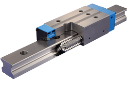
Here you can see what I'm talking about. I'm sure you knew that and probably meant something else, or I didn't understand what you meant.
Thanks for the explanation
-
09-18-2017, 07:49 PM #18
Community Moderator
- Join Date
- Mar 2003
- Posts
- 35538
Re: Is it at all possible to build a metalworking CNC router out of aluminum profiles
I meant "All the balls that are in contact with the rail."
With a round rail, the ball bearings on the opposite side of where the force is applied aren't really doing anything.
With a profile rail, all of the balls in contact with the rails are sharing the load. And there are a lot more balls in contact.Gerry
UCCNC 2017 Screenset
http://www.thecncwoodworker.com/2017.html
Mach3 2010 Screenset
http://www.thecncwoodworker.com/2010.html
JointCAM - CNC Dovetails & Box Joints
http://www.g-forcecnc.com/jointcam.html
(Note: The opinions expressed in this post are my own and are not necessarily those of CNCzone and its management)
-
09-18-2017, 09:05 PM #19
Member
- Join Date
- Feb 2017
- Posts
- 32
Re: Is it at all possible to build a metalworking CNC router out of aluminum profiles
Oh I'm sorry I didn't understand what you were saying. Originally Posted by ger21
Thanks again for your explanation it really helped me see the difference.
-
09-18-2017, 09:44 PM #20
Member
- Join Date
- Feb 2017
- Posts
- 32
Re: Is it at all possible to build a metalworking CNC router out of aluminum profiles
Hi NIC
There is something odd:
Look at those low power and torque requirements that can't be right?!

 Reply With Quote
Similar Threads
-
Aluminum router build - Could use some input
By Tumblebeer in forum DIY CNC Router Table MachinesReplies: 6Last Post: 06-26-2014, 01:52 PM -
New Machine Build - Router for aluminum
By pupetxls in forum DIY CNC Router Table MachinesReplies: 9Last Post: 05-28-2014, 03:14 PM -
need to build a cnc router / mill for aluminum
By axkiker in forum DIY CNC Router Table MachinesReplies: 18Last Post: 07-30-2013, 07:36 AM -
24 X 72 X 5 Aluminum Router Build - Need Advice
By BigSmith in forum DIY CNC Router Table MachinesReplies: 10Last Post: 02-01-2011, 06:02 AM -
New Build - Aluminum Router Table - 2' x 4'
By wwendorf in forum DIY CNC Router Table MachinesReplies: 15Last Post: 05-05-2010, 09:41 PM
