


Hi,
excuse me "thread jacking", I just wanted to thank "handlewanker" for posting the "hand planer device", I'm amazed that I've never come across one before! It is so obvious! Mind racing, how about adding a grinder?
Thanks again, Matthew
Thread: A benchtop cnc lathe build
Results 261 to 280 of 296
-
07-25-2008, 10:40 AM #261
 Registered
- Join Date
- May 2004
- Posts
- 100
hand planer
-
07-25-2008, 01:55 PM #262
Registered
- Join Date
- Mar 2006
- Posts
- 357
Ian, Thanks for all the tips on my new project. Hopefully I can do a little more work to it this weekend and post some progress pics. I'll have to make a lot of compromises from a true horizontal boring machine but it should be a cool little machine when finished. I pretty much only work at the smallish hobby level of parts size( model engines etc) . So it should be very capable for my needs.
One question for you, Do you see any need for me to add a tailstock? I plan on adding a overarm support so I won't need to use the tailstock for horizontal milling support like in the pic of that little old bore mill.
I'm thinking of just having a slide with a outboard bearing for line boring duty which will be much simpler to make.
Thanks so much for the planer info! I'll give that a project a go once I finish my current project. I think I can handle that project. I have a old mini lathe bed. I might make a small planer for thatbed to first get the hang of how it all works before going for broke on my SB.
Steve
-
07-25-2008, 09:18 PM #263
Member
- Join Date
- Sep 2006
- Posts
- 6463
Hi Steve, the tailstock is just to support the line bar, nothing else, and only needs to be adjustable across the bed to ensure inline accuracy, same as a lathe tailstock, but could be fixed.
It does need to be positioned along the bed so that the line bar support distance can be as short as possible to prevent whip.
If the overarm is attached to the headstock and protruding like a round bar in a bush, then this would add deflection loads to the headstock if the end is unsupported.
The overarm needs to be able to rise with the headstock to whatever centre height is required, but alternatively, if the overarm is attached to the top of the column and in a fixed position with the overarm carrying a bracket that is vertically adjustable, this would probably be a compromise, from the rigidity point of view.
Much simpler to just add a simple tailstock mount on the bed siimilar to the existing slide section already on the bed, and make a round column and adjustable bar support, similar in design to the table support on a bench drill, and if you have one going spare you could probably utilise that by dispensing with the base and attach it to the bed slide.
You probably wouldn't have to make much modification to the the drill table support, just add a square tube housing with a bushed bore in place of the drill table.
When the line bar is in place it would automatically line up the bush in the horizontal plane, and the vertical plane can be set head end and tail end with a dial indicator and height gauge etc.
Hi mattinker, there have been a couple of bed rejuvenators made, the first one described in the Model Engineer circa '80s used a die grinder type of thingy, that was inclined to the angle of the Vee and ground the slideway on its end like an end mill.
This gave me the incentive to design and make the planer type, which is far more versatile, enabling all wear surfaces top and bottom to be cut as required.
Both types use the unworn sections of the bed to guide the device.
The current trend in lathe bed design is flame hardened beds, and I think when they show wear it will be a different story, but not impossible.
The method descreibed is for the DIY person who doesn't have the money to get the bed ground commercially, or who just likes doing it themselves anyway.
A Myford type of lathe with a square way bed could be rejuvenated simply with a small square, a straight edge, micrometers and a good scraper, plus a bit of elbow grease, piece of cake.
One thing must be remembered, what you take off of the bed top must also be taken off of the apron top due to the bed taking up a lower position once recut, and so dropping the centres of the leadscrew, feed shaft and rack mechanism, but that's easily done with an angle grinder, file and scraper.
Ian.
-
07-25-2008, 10:06 PM #264
Registered
- Join Date
- May 2004
- Posts
- 100
Thread squatter, again!
Hi,
I promise not to be too long!
I have a 1944 Colchester, not flame hardened. It has very little wear, so I don't think I'm going to need your system, just good to have in mind!
Thanks, Matthew
-
07-30-2008, 04:08 AM #265
Member
- Join Date
- Sep 2005
- Posts
- 1195
Gilman
Hi Steve,
I can not go to http://www.skfpt.com/hrd-way-features.html. Maybe this site been erased. Another stupid question: Why people do not make cnc lathe the way you did, its cheaper compare if people using convensional bedways that has alot of friction. With the way you did, people need a smaller motor. I will also make cnc lathe the way you did, since I already have that HIWIN, i have big one. But I need some design for headstock. Thanks. Aristo.
-
07-31-2008, 03:09 PM #266
Member
- Join Date
- Sep 2005
- Posts
- 1195
Hi Steve,
I can open that website, I do not know why. It could be a lot of peoplego there. Good site. Thnaks. Aristo.
-
07-31-2008, 11:18 PM #267
Registered
- Join Date
- Mar 2006
- Posts
- 357
Aristo,
thanks, The little lathe was a lot of fun to build, a great learning experience as well.
It works, got built pretty quickly and not a thing, nothing, has gone wrong with it.
Hopefully I'll be as lucky with my current project based on the Gilman slide.
Not sure what's up with the skf link. I have no problem accessing it from my end.
Steve
-
08-01-2008, 01:37 AM #268
Member
- Join Date
- Sep 2005
- Posts
- 1195
Steve,
Thanks, I can open that site already, easy. Aristo.
-
01-07-2009, 08:50 AM #269
Registered
- Join Date
- Dec 2004
- Posts
- 229
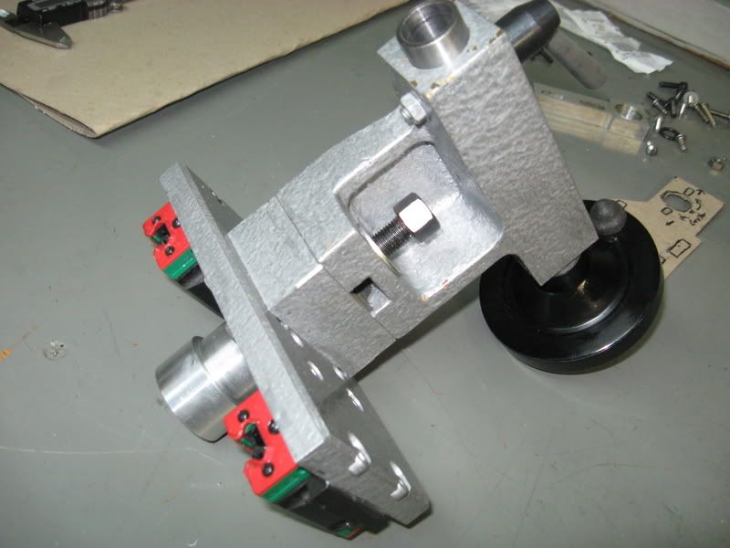
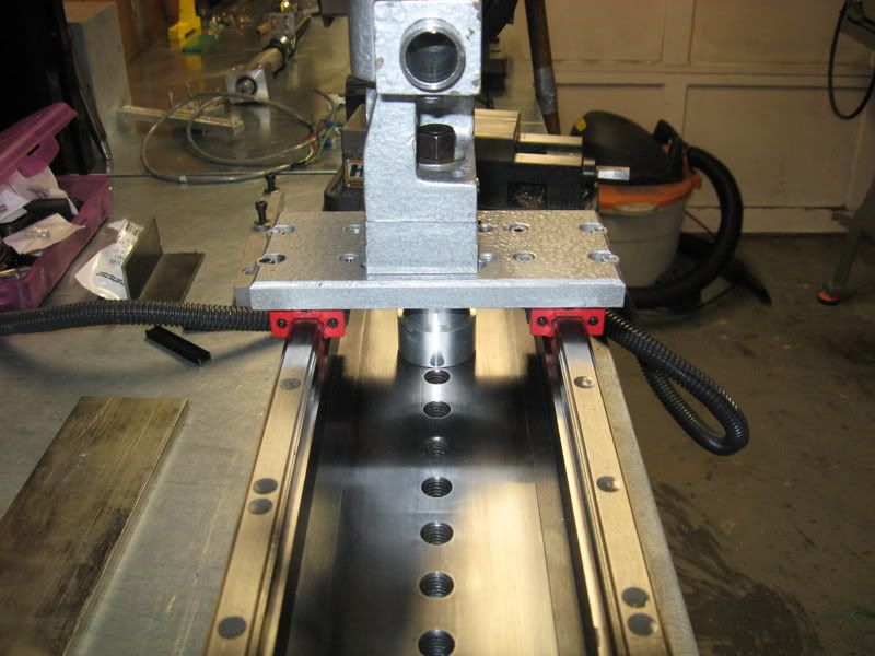
Steve,
Could you provide a picture of how you are clamping your tailstock to the bed? I am not completely picturing how you ended up doing it.
Did you buy and retrofit the mini lathe tailstock that LMS sells?
And lastly, could you share what steps you took to align the tailstock ram to the lathe spindle?
Thanks,
dfro
-
01-08-2009, 06:36 PM #270
Registered
- Join Date
- Mar 2006
- Posts
- 357
dfro,
The tailstock uses a pillar underneath with a stud to attach to any of the central threaded holes in the bed. Very rigid setup but slow to change positions. I seldom ever use the tailstock.
It was dialed in using an indicator in the spindle to sweep the MT2 taper inside the tailstock ram.
Yes, it is a retrofitted mini lathe tailstock.
Hope this helps.
Steve
-
01-10-2009, 08:54 AM #271
Registered
- Join Date
- Dec 2004
- Posts
- 229
Steve,
Thank you! The pics and your explanation make your design very clear. That looks like a very good solution.
I am retrofitting an old Atlas lathe bed, so I won't be able to do it this way. I am interested in trying your idea of tying the longitudinal z motion of the tailstock to a leadscrew. I would then clamp it in place with a threaded clamping collar.
I am concerned about how much the tailstock leadscrew might flex under the clamping pressure of holding a workpiece with a live center, for example. Do you see any major drawbacks to this method.
Thanks,
Dave
-
01-10-2009, 06:36 PM #272
Gold Member
- Join Date
- Jan 2006
- Posts
- 2985
Dave
Is this the flat way style lathe bed? I have one of those lathes. The design for the way the tailstock clamps to the bed is pretty straight forward. I could take a few pics if you want. I would recommend using a stock tailstock, but I don't think you would have enough room for the carriage once it is CNCed. Maybe you could use an atlas tailstock and just add a spacer so you have enough room underneath for your mechanicals.
Matt
-
01-22-2009, 10:06 PM #273
Registered

- Join Date
- Nov 2003
- Posts
- 104
would A-36 be a good steel to use for a base like this lathe?
-
03-13-2009, 05:08 PM #274
Registered
- Join Date
- May 2008
- Posts
- 2
Info need please,
Hi Steve,
Nice work on your CNC lathe, I have a little question about your spindle motor drive. You tell that you use a Minarik drive, could you tell me the model number of your drive?
I am trying to find a good drive for my spindle motor.
Thank you,
Gaet
-
04-25-2009, 03:10 AM #275
Registered
- Join Date
- Jan 2009
- Posts
- 82
Thread digging a little here but WOW! This lathe is awesome. Nice job:cheers:
-
04-25-2009, 08:25 PM #276
Registered
- Join Date
- Mar 2006
- Posts
- 357
Thanks Joe.
The lathe has now changed hands and belongs to my good friend Rube.
He will be making some improvements to it so it will be even better.
Steve
-
04-26-2009, 06:55 AM #277
Registered
- Join Date
- Jan 2009
- Posts
- 82
Could U tell me what the distance between centers ended up being using the 24" ground plate? Thanks
-
04-26-2009, 04:32 PM #278
Banned
- Join Date
- Apr 2004
- Posts
- 63
Hi Joe...the distance from tip of the jaw chucks to the tip of a live center in the tailstock fully retracted is just over 8 1/2". However, I'm going to flip the riser block under the headstock and gain ~1 1/4" more.
Yep, Steve did an awsome job on this thing and I am proud to be the one that ended up with it (however I could have done without the circumstance that got me here). There is not much I can improve on it, but I'll eventually start a new thread when I get some progress made on rebuilding it. Speed demon Steve I am NOT!!! Right now, I am cading it all up and working out some ideas. Oh yeah...and spending money on it...LOL:banana:
-
04-26-2009, 04:55 PM #279
Registered
- Join Date
- Jan 2009
- Posts
- 82
Thanks for the info I would like to start one of my own and was lurking ebay for that base plate. Originally Posted by Rube

-
04-27-2009, 05:56 AM #280
Member
- Join Date
- Sep 2006
- Posts
- 6463
WHAT........you got rid of the lathe now it's up and running...I'm astounded.
Perhaps you have something new in the pipeline, a new design based on the old one?
We are hungry for details.
Ian.

 Reply With Quote
Similar Threads
-
80/20 benchtop lathe build
By LeeWay in forum Vertical Mill, Lathe Project LogReplies: 87Last Post: 06-15-2015, 01:35 AM -
DIY benchtop mill build
By mkuivamaki in forum Benchtop MachinesReplies: 36Last Post: 03-19-2014, 08:54 AM -
Looking to build my own benchtop cnc!
By rim basses in forum Benchtop MachinesReplies: 0Last Post: 10-09-2009, 07:20 PM -
Not a Benchtop mill but Dang! You have to see this build.
By praetor in forum Benchtop MachinesReplies: 19Last Post: 05-19-2009, 10:58 AM
