


Feel free to comment / criticize in this thread- and know that I just might disagree with you, and that needs to be ok. It's my money being spent here, so that gives me creative power but if you want to add to it, feel free!
Ok, so things keep progressing with my other build which many of you are following, and my interest is is starting to turn more and more to metal milling. The concept of high speed machining is making it hard to turn my mind off when I go to bed, and now with some better tooling I am starting to look to new designs and functions.
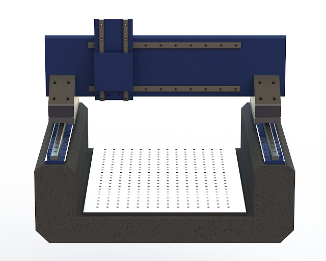
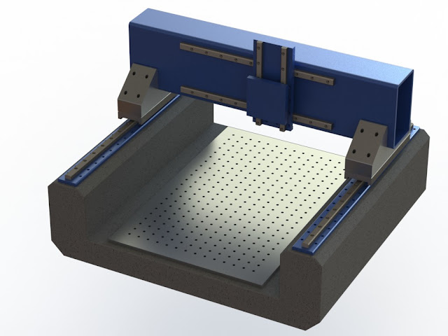
Enter my new little mill design. Don't get too critical yet- I made this from scratch in 45 minutes so bear with me. It still needs a lot of work, and ballscrews would probably help considerably with the operation of the machine.
Some simple observation so far:
It's made of concrete. There is some steel inside to make everything line up and such, but yes, the base will be molded out of some sort of composite. Have not given exactly what will go into it so far, so perhaps an epoxy, or perhaps something else but it will be HEAVY. Interesting fact: Solidworks does not seem to have concrete or epoxy in its material list, so right now I just have "lead" marked for the base material. Mass properties excerpt:
Lead of course is heavier then rock, but I still thought that fact was kind of fun. I'm not doing any FEM analysis yet, but my guess it it's pretty stationary.Code:Mass = 2864.36 pounds Volume = 11408.08 cubic inches Surface area = 11679.35 square inches Center of mass: ( inches ) X = 0.04 Y = 5.58 Z = 18.53
Another note: Here on the drawing it is using 25mm rails. I have a 45mm rail in an 84" configuration, that if cut in half would work quite nicely for the X. I know that the 25mm guides are strong as hell, and the 45's gotta be absolutely crazy strong. I plan on pulling some specs and see how load bearings / flex compares and go from there. Could be interesting.
Third, there is not much structural aluminum on this build. For machining reasons, the triangle risers the gantry sits on are currently aluminum, but that might change. It's a flippin 4x6x14" block, so my guess is it probably does not concern me too much as far as weakness goes.
Also, the carriage I have here is still little. I have not had a chance to update it, I stole it from another model I made last week.
Stay tuned, there is much more to come. It will stay in the digital world for a while while I finish out my other build, but this one will come one day.
Results 1 to 14 of 14
-
12-05-2011, 11:14 PM #1
 Registered
- Join Date
- Apr 2010
- Posts
- 363
Crane's NEXT next CNC... Little man syndrome
-
12-06-2011, 01:34 AM #2
Registered
- Join Date
- Apr 2010
- Posts
- 363
-
12-06-2011, 04:22 AM #3
Registered

- Join Date
- Feb 2009
- Posts
- 1290
Very cool, I'm also looking at a small machine. I have some THK linear slides I want to use. I will watch this one.
Thank You.
-
12-06-2011, 05:03 AM #4
Registered
- Join Date
- Apr 2010
- Posts
- 363
It might be a while before I actually get around to building this one, as I really need to finish my big CNC first. This one will be in the planning stage for a while, so for now it's just a Solidworks model. I will continue to play with it and refine. I am looking forward to running some FEM on it to see where it stands.
-
12-06-2011, 05:18 AM #5
Registered

- Join Date
- Feb 2010
- Posts
- 331
i really like the initial design. i have begun panning my next machine as well, and it will be focused on metal.
the one suggestion i have right now is to check out the epoxy/granite machine/section. that is what i plan on using for my next machine.
-
12-06-2011, 05:26 PM #6
Registered
- Join Date
- Sep 2011
- Posts
- 0
Estimating concrete at 2400 kg/m^3, thats going to be like 500 lbs!

-
12-06-2011, 06:08 PM #7
Registered
- Join Date
- Mar 2004
- Posts
- 1306
Cool design. I have been collecting parts for the same sort of machine, and have decided to bodge up a test frame in MDF. I'll play with this to get a feel for it, and then cast a mineral epoxy frame for it.
Have you thought about making it a fixed gantry, with a moving table? Seems to me to be a simpler build, as you can run one central ball screw for Y, rather than two slaved Y ball screws.

I am using one of the small cast iron t slot tables they sell for the chinese 10x20 lathes.
Once you stack up the spindle, it's mount, the adapter plate to mount to Z, the Z rail, the adaptor plate (or two) to interface Z to X, you end up with a much less symetrical machine. I am not finished modelling mine yet (no gantry sides, no spindle interface, no X rails or screws etc) , but this will give you an idea...Regards,
Mark
-
12-07-2011, 07:10 AM #8
Registered
- Join Date
- Apr 2010
- Posts
- 363
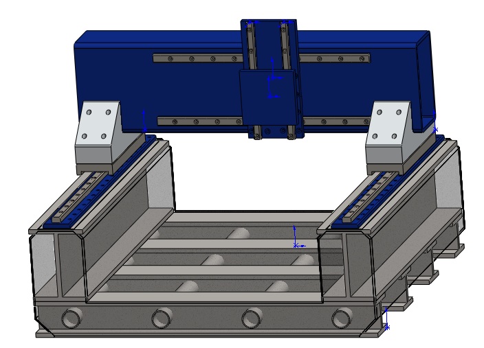
This has been a work in progress, and not everything is in the digital model of course, but I did make some progress. Here is the idea for the inner frame:

Things to consider-
1. Welding the tubes between the I beams seems to me a good setup. It's not clear in the model, but the intention is to put holes in the I-beams, and then have the tubes solid all the way. I think I have the spec'd at 2" 3/8 wall, but that is easily changed. This is just a proof of concept at this point. Some advantages to this: Torsion box, even without the composite fill. Also welding the seams where the tubes and I beams meet seems to appear to be a little more immune to warpage when welding. Could be wrong about that, but that what it looks like to me.
Rumor is I beams off the rack tend to be fairly straight, at least more so then rectangular tube.
Also seems that the mold would be fairly easy to make- or just might double as the exterior panels. I have always wanted to develop my sheet metal skills.
Looks like my left rail already vibrated loose. Better secure it better! :lol:

Would be nice to leave these exposed to attach a base

Here's the kicker. We have guys in town with machines big enough to flatten this. If I brought in a base (composite or not) they can easily level the tops as shown in red below. This would set me up for some pretty good accuracy. It could even be taken a step further and key ways for the X rails could be set- lay them in, and they are straight.

After all, the whole idea of this project is DFM.
-
12-07-2011, 03:48 PM #9
Registered
- Join Date
- Mar 2004
- Posts
- 1306
Sorry, I somehow misunderstood that this would a small machine. I just went back and reread the machine dimensions.
If you make that up as a weldment, do you have someone with a furnace to normalise it?Regards,
Mark
-
12-07-2011, 04:03 PM #10
Gold Member
- Join Date
- Jul 2007
- Posts
- 1602
Have you read the Epoxy Granite thread? There is a lot of good information there: http://www.cnczone.com/forums/epoxy_..._concrete.html
While concrete has been used, it is not without its problems, corrosiveness, shrinking etc...
If you go the E/G route, I don't think you will need that much structural metal. Anchored strips to secure your rails should suffice. In the E/G thread they mention a build thread on a German CNC site. The fellow there went on to produce this frame: http://www.cnczone.com/forums/epoxy_...crete-378.html
This is a good read: http://www.mech.utah.edu/~bamberg/re...e%20Design.pdf. He used a concrete fill for damping but isolated it from the frame and used a concrete that would expand slightly.
E/G is about the same density as Aluminum so you can get an idea of the weight by selecting aluminum as a material.
bob
-
12-08-2011, 01:06 AM #11
Member
- Join Date
- Apr 2004
- Posts
- 5737
What makes it go?
You don't seem to have made any provision for mounting the ballscrews - were you going to use slaved dual X-axis screws, or rack and pinion? Does the Y-axis drive mechanism hide in that gantry somewhere and engage through a slot, or is it surface-mounted?
Andrew Werby
ComputerSculpture.com — Home Page for Discount Hardware & Software
-
12-08-2011, 04:47 AM #12
Registered
- Join Date
- Apr 2010
- Posts
- 363
The drawing is far from complete- and no, ballscrews have not been put into the mix yet, although I have a good idea of how they will work.
There is some good info in the epoxy/granite thread. I will have to read into it some more. It's finals week so things have been kinda busy. Really cuts into my machine design time!
Alex
-
12-12-2011, 07:13 PM #13
Registered
- Join Date
- May 2010
- Posts
- 307
I like the design so far! Keep us updated... sometimes for me the most fun I have here are watching other's ideas adapt and change as they try to figure out just how they're going to manufacture their machines.
-
03-21-2023, 06:58 PM #14
Member
- Join Date
- Dec 2021
- Posts
- 54
Re: Crane's NEXT next CNC... Little man syndrome
As It is old post but it gave me an idea as i am looking to build fixed column moving table cnc.
Hope to start soon like this way after sourcing parts

 Reply With Quote
Similar Threads
-
Crane's 25x25 Solsylva Build w/ Pictures
By crane550 in forum DIY CNC Router Table MachinesReplies: 220Last Post: 07-25-2017, 09:30 AM -
Crane's Next CNC
By crane550 in forum DIY CNC Router Table MachinesReplies: 192Last Post: 10-18-2016, 04:29 AM
