


Tom,
Happy Labor Day Everyone!
I have also attached a few photos of my progress, I will clean up the wiring once all functions are confirmed. I have also uploaded the revised wiring schematic to include the added OPTO7 circuit.
Great. What did you change?
I had the polarity of the micro relay board incorrect, The way we have it wired per the schematic, I was under the impression that Kanalog would supply a 24VDC signal, however the signal that Kanalog supplied to the micro relay board is -24VDC. We (Jim and I) did add another input (OPTO 7+) from the CR1 relay (pin 24) and a -24VDC to the other side of the input (OPTO 7-). When the E-Stop button is depressed it will deenergize the power to the servo contactors, thus shutting down the servos. I have confirmed the proper start-up and button operation, everyone is Happy on those circuits, I can go ahead and clean up those wires and place in their permanent home on the panel.
Will I also have to do SetBit(143) on OPTO 7 input to verify?
You need to configure, test, and tune the entire machine first. Return to post 48.
I will go back and view post 48, and start checking the axis, I clicked on the link in the post, these are the steps that it brought me to. Will I copy the KanalogInitialPID.mot to the C Code ->clipboard button on the Config screen, then load the channel?
Initial Setup/Testing for Analog Amplifiers
There is a starting configuration for KFLOP+Kanalog called KanalogInitialPID.mot in the \KMotion\Motors folder. Load it into an axis channel from the KMotion Configuration Screen. The basic first steps are to verify the hardware:
- check the encoder counts correctly as shown on the KMotion Axis Screen Position (a KFLOP Axis must be configured as Encoder Input with the Input Channel0 set to the channel where the encoder is physically connected)
- check that the DACs can command the Amplifier to control motor speed. Test Console commands like DAC0=200 to Output ~ -1V (with the axis disabled - if any axis is enabled and continuously writing to the DAC any Console Command will be overwritten)
- If steps #1 and #2 above work correctly, enable the Servo using the Step Response Screen. Zero, Enable. The motor should then attempt to weakly hold position.
Configuring DAC and Encoder Channels
I think our software/documents some what over use the word channel which can confusion. There are Motor Axis Channels, DAC Output Channels, and Encoder Input Channels which are all different things. This diagram may help:
KFLOP Functional Diagram
Any KFLOP Motor Axis Channel can be configured to make use of any DAC or any Encoder by specifying the Input and Output channels. See:
Input Channels
The KanalogInitialPID.mot configuration file is an example of a Kanalog Axis using DAC #0 and Encoder #0. If simply loaded into multiple Motor Axis Channels it will configure all the Motor Axis to all use DAC 0 and Encoder 0 as their I/O devices.
So for example for the Second Motor:
- select Axis Channel #1
- load the KanalogInitialPID.mot configuration
- Change the Input Channel and Output Channel settings to the Encoder and DAC you want that motor to use (ie. #1 and #1)
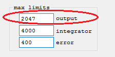
Max Output For DACs
Note the Maximum Output range for the DACs is +/-2047 DAC Counts. Attempting to output larger values will cause a wraparound effect and runaway or following error fault. So set the Max Output to 2047 or less.
Testing Analog Amplifiers
One way to perform a basic test of an Analog Amplifier to see if it is working and likely capable of being driven by a Kanalog DAC Output is to apply a small voltage to the input to see if the motor drives. A 1.5V battery in series with a 1K Ohm resistor is one possible voltage source. The 1K Ohm resistor should limit the current in case a mistake is made. When applied the motor should drive at a controlled 15% (Speed if the drive is in Velocity mode, or torque if in torque mode). Reversing the battery should reverse the motor direction.
Drive Enables - Axis Drift with Servo Disabled - Power up Issues
Unlike digital values, analog values will always have some amount of noise and error on both inputs and outputs. This means that commanding Zero Volts is unlikely to be ever be exactly Zero and some small torque or drift will occur with Zero Volts commanded. The only way to guarantee no motor drive is to disable the Drive.
Kanalog is designed to be precise and linear but not highly accurate (+/- 1% components are used). Absolute accuracy on the servo output is not normally a requirement for good servo control. This is not a problem when the servo is enabled as the servo will command whatever output necessary to hold the desired position. However whenever the servo is disabled the Drive should also be disabled to avoid any motor drive or drift.
The Drive enable signals can be interfaced to KFLOP. Any I/O can be used as the Drive enables are handled in software as a User Program (see the watchenable.c example).
Often the Kanalog Relay Driver Outputs or Opto Isolated Outputs can be used for Drive Enables.
However please note that unfortunately the Kanalog Outputs Power up in an initially undetermined state for several seconds until KFLOP boots up. If this is a problem for your system then another means of keeping the Drives disabled should be used during initial power up. The Kanalog SWE Relay Output Driver is guaranteed to remain disabled until KFLOP fully boots and all Kanalog Outputs are initialized to the off state.
Thread: Dynomotion
Results 61 to 80 of 155
-
09-06-2021, 01:55 PM #61
 Registered
- Join Date
- May 2009
- Posts
- 136
Re: Dynomotion
-
09-06-2021, 06:03 PM #62
Junior Member
- Join Date
- May 2006
- Posts
- 4045
Re: Dynomotion
Happy Labor Day Mark,
Strange it should have still worked just with opposite polarity.Great. What did you change?
I had the polarity of the micro relay board incorrect,
Actually Kanalog Optos are like a switch. Depending on how its is wired when the "switch" activates it can either source +24V or sink to 0V.however the signal that Kanalog supplied to the micro relay board is -24VDC.
First observe Input Bit 143 on the digital IO Screen. Does it come on when EStop is pushed and go off when not pushed?We (Jim and I) did add another input (OPTO 7+) from the CR1 relay (pin 24) and a -24VDC to the other side of the input (OPTO 7-). When the E-Stop button is depressed it will deenergize the power to the servo contactors, thus shutting down the servos. I have confirmed the proper start-up and button operation, everyone is Happy on those circuits, I can go ahead and clean up those wires and place in their permanent home on the panel.
Will I also have to do SetBit(143) on OPTO 7 input to verify?
Inputs can not be set or cleared. They can only be Read. Later in a forever loop you might read this bit and if active do something like disable all the KFLOP Axes which will cause any program to abort.
No, please read more carefully. That is a motor Configuration file not C Code. You might also read this.Will I copy the KanalogInitialPID.mot to the C Code ->clipboard button on the Config screen, then load the channel?TK
http://dynomotion.com
-
09-06-2021, 06:30 PM #63
Community Moderator
- Join Date
- Dec 2013
- Posts
- 5717
Re: Dynomotion
Tom, Originally Posted by TomKerekes

To clarify, there are jumpers on the relay boards for active high or active low inputs. I just had Mark try the jumpers in the opposing position, and it worked. The other issue was that the E-stop permissive relay output was wired incorrectly. I helped Mark get through this yesterday, so the E-stop/enable circuit is now working correctly, as well as the Kanalog outputs being able to energize the drive contactors.
I have to admit that I have not reviewed the Dynomotion documentation, so I can't be of much help beyond this.Jim Dawson
Sandy, Oregon, USA
-
09-06-2021, 08:21 PM #64
Junior Member
- Join Date
- May 2006
- Posts
- 4045
Re: Dynomotion
Hi Jim,
Like I said I would have thought that would have just changed the polarity. Not changed it from not working to working. I also worry the relay board is not being driven correctly but it is hard to say without any input specifications. I believe currently when deactivated the input is left floating which may not guarantee a proper state.To clarify, there are jumpers on the relay boards for active high or active low inputs. I just had Mark try the jumpers in the opposing position, and it worked.
Thanks for your help.TK
http://dynomotion.com
-
09-11-2021, 03:31 PM #65
Registered
- Join Date
- May 2009
- Posts
- 136
Good morning All, Originally Posted by TomKerekes
I’m back at it this morning. I have checked the Opto7 (143) input when the E-stop is depressed. With the E-Stop the state is off (unchecked), when you release the E-Stop the state then changes to on (checked). Is this reversed if what Kanalog wants to see?
Also I tried to send a signal to the X-Axis via the DAC0=100 command. Nothing happens, no movement from the servo. Does the E-Stop input have any relation to the Enable the Servo test?
Please advise.
Thanks, Mark
-
09-11-2021, 04:53 PM #66
Community Moderator
- Join Date
- Dec 2013
- Posts
- 5717
Re: Dynomotion
Were you able to run the servo from the DMM software screen? You need to do that first, then setup Analog Torque or velocity mode to run from the Kanalog analog output.
Jim Dawson
Sandy, Oregon, USA
-
09-11-2021, 04:55 PM #67
Registered
- Join Date
- May 2009
- Posts
- 136
Jim, Originally Posted by Jim Dawson
No. I wasn’t able to run the DMM tests.
-
09-11-2021, 06:57 PM #68
Registered
- Join Date
- May 2009
- Posts
- 136
The X-axis now responds in a CCW direction as you look at the gear, when you command DAC0 = 100 Originally Posted by seapacer2
Now on to the other axis.
Thanks,
Mark
-
09-12-2021, 10:34 PM #69
Registered
- Join Date
- May 2009
- Posts
- 136
Re: Dynomotion
Hello Tom,
It seems that I have made some progress after this weekend. I was able to run all three (3) axis from the KMotion console by a command. However, I do have a few questions. Here are at the steps that I performed up to today
Performed the DMM Servo Test. For this test, I manually connected a USB cable to each servo drive via RS232 connector (JP2) on the DYN4 servo drives, then activated the I/O input to turn each drive on from Kanalog. In the constant speed test, I was able to ramp up the RPM and reverse direction on all servos. After confirming that I could control both directions and the speed from the DMM software, I set all servos in the Analog input and servo modes.
Preceded to the KMotion Servo Test, in this test, I'm going to try to control servo speed and direction through the motion control board from the KMotion Console. I started with the "X" axis utilizing these steps:
- Ran KMotion software from desktop and opened the console screen, configuration screen, I/O screen (to turn on my servo contactors through the OPTO outputs), and the axis screen.
- From the Configuration screen, I selected "Channel 0" for the "X" axis and then "Loaded Channel" with the KanalogintialPID.mot file.
- Powered the the servo drive and contactor by changing the state to on for Bit 147 and 148. (OPTO Out 3,4).
- Enter DAC0 = 100 command and hit "Send" - Servo started turning in a CW rotation and you could monitor it on the Axis screen by watching the encoder value increase.
- Enter DAC0 = 0 command and hit "Send" - Servo stops rotating.
- Enter DAC0 = -100 command and hit "Send" - Servo started turning in a CCW rotation and it could be monitored on the Axis screen by watching the encoder value decrease.
- After confirming the "X" axis for proper operation, I then proceeded to the other Axis. -
- AI then completed the tests for all the axis and confirming the all the same results, it looks like that I'm able to control all servos for the motion control board, please let me know if this is not the case and I'm in correct.
This programming has been a challenge and I'm learning on the fly.
However, I have a few questions.
1.) On the Axis screen, can you disable the drive? I was able to operate the servo rotation through the console even though the drive was not enabled, (Screen Shot).
2.) During the KMotion Servo test, I opened the Configuration Screen and loaded the channel 0,1,2 (X,Y,Z) utilizing the KanalogintialPID.mot file. (Step 2 in the above test), I was able to command any axis during the test, it didn't seem to matter what channel I had loaded on the Configuration screen.. Should I have been only able to command the channel that I had loaded in the Configuration Screen?. (Screen Shot)
-
09-13-2021, 01:17 AM #70
Junior Member
- Join Date
- May 2006
- Posts
- 4045
Re: Dynomotion
Hi Mark,
No, those enable the KFLOP Axis. When the KFLOP Axis is enabled then it will command the DAC to move the motor to attempt to get the encoder to match its commanded destination (Servo). When the Axis is enabled any DAC commands on the console will have no effect because the Axis has control of the DAC,1.) On the Axis screen, can you disable the drive? I was able to operate the servo rotation through the console even though the drive was not enabled, (Screen Shot).
The Configuration for a KFLOP Axis will determine what and how it drives the motor when it is enabled.2.) During the KMotion Servo test, I opened the Configuration Screen and loaded the channel 0,1,2 (X,Y,Z) utilizing the KanalogintialPID.mot file. (Step 2 in the above test), I was able to command any axis during the test, it didn't seem to matter what channel I had loaded on the Configuration screen.. Should I have been only able to command the channel that I had loaded in the Configuration Screen?. (Screen Shot)
You might think of a KFLOP Axis as a cruise control in a car and the DAC the gas pedal of the car. It doesn't matter how the cruise control is configured if it is off. You can still push on the gas and drive. And when the cruise control is enabled it doesn't really work to be using the gas pedal.
HTHTK
http://dynomotion.com
-
09-13-2021, 01:31 AM #71
Registered
- Join Date
- May 2009
- Posts
- 136
Re: Dynomotion
Tom,
So I guess we are making progress? The next step after reading some other posts are the servo plot testing, is this correct?
You had mentioned in post 51 that the OPTO outputs could be turned on automatically through a program, I'm currently turning them on through the I/O digital screen to activate the contactors and servo drives. What file and what type of script will I have to do to accomplish this? Or should I continue to wait and do further testing?
Thanks,,
Mark
-
09-13-2021, 01:43 AM #72
Junior Member
- Join Date
- May 2006
- Posts
- 4045
Re: Dynomotion
Hi Mark,
Yes!So I guess we are making progress?
YesThe next step after reading some other posts are the servo plot testing, is this correct?
btw you've been referring to things as "programming" which really are not. More just commanding IO. After everything is figured out and you have the final configuration and tuning these can be exported to a C Program. It's a bit demeaning to call a C Program a "script" as it is much faster and more powerful.You had mentioned in post 51 that the OPTO outputs could be turned on automatically through a program, I'm currently turning them on through the I/O digital screen to activate the contactors and servo drives. What file and what type of script will I have to do to accomplish this? Or should I continue to wait and do further testing? This C Program can also enable anything that needs to be enabled. You might read this.
TK
This C Program can also enable anything that needs to be enabled. You might read this.
TK
http://dynomotion.com
-
10-05-2021, 02:04 AM #73
Registered
- Join Date
- May 2009
- Posts
- 136
 Re: Dynomotion
Hello Tom,
I made some more progress this weekend, started wiring the limit switches
.
Screen shot of the "Z" axle limit switches wired and NOT activated.
Screen shot with the "Z+" and "Z-" switches activated, separately, one (1) at at time and both at the same time. . I will finish the "X" and "Y" axis switches this weekend if this is correct?
Since I only have one (1) day a week to work on my machine, I'm working on getting it in the garage at the house. This will give me more resources and time to work on programming, I also working on a mobile base this weekend. Once I get all the limit switches wired correctly, I will start on servo turning.
The limit switches are utilizing Opto In 3.4 and 5 and utilizing Bits 139,140 and 141. I will be sure to add this into my table that I created. .
Still need to finish some welding, painting and installing the caster and leveling pads.
-
11-09-2021, 01:45 PM #74
Registered
- Join Date
- May 2009
- Posts
- 136
Re: Dynomotion
Good Morning,
I have been really busy the last couple of weeks trying to get my machine moved. I fabricated a mobile base that the machine bolts too and still have to mount the leveling feet. The machine now is sitting in my garage, this will make programming a bit easier now that I have access to it all the time. I will be installing a small sub panel that is mounted next to the main breaker panel in the garage. I have that being delivered at the first of next week.
-
12-06-2021, 06:37 PM #75
Registered
- Join Date
- May 2009
- Posts
- 136
Re: Dynomotion
Good Afternoon All,
Machine is in my home garage and it has been wired to a stand alone subpanel for 230V, the machine was powered up this weekend and all components are powered up, just like at my shop. The next step in the programming process is servo turning, can you conform this Tom?
Thanks,
Mark
-
12-06-2021, 06:45 PM #76
Junior Member
- Join Date
- May 2006
- Posts
- 4045
Re: Dynomotion
Hi Mark,
I believe it is ready for testing/tuning the axes. Please work on one axis at a time.TK
http://dynomotion.com
-
12-09-2021, 12:20 AM #77
Registered
- Join Date
- May 2009
- Posts
- 136
Good afternoon,
I have fired up my machine, getting ready to test and tune the the servos. Does And have looked in the KFLOP manual, can anyone get me, this is the portion that I am at a lose. Can anyone direct me to a step by step thread on how to go about this process?
Thanks, Mark
QUOTE=TomKerekes;2484498]Hi Ma
I believe it is ready for testing/tuning the axes. Please work on one axis at a time.[/QUOTE]
-
12-09-2021, 01:13 AM #78
Junior Member
- Join Date
- May 2006
- Posts
- 4045
-
12-12-2021, 07:03 PM #79
Registered
- Join Date
- May 2009
- Posts
- 136
Re: Dynomotion
Good Morning,
It is nice to be able to work on my machine in my own garage, where I have access to the internet to refer back to the forum for reference. That is one thing I was struggling with at my shop, I would load everything on a flash drive, just my luck and in experience I would get down there and not have enough of what I needed.
The programming portion still is challenging for me and I still have a lot to learn. The last two (2) days have been been reading over and over a couple of links that are attached to the WIKI site, the one that I thought was the most detailed was started by PeterTheWolf on a Tree325 Retrofit. I have back tracked a little to get a better understanding and rechecked a few things, and these are the testes I just completed.
- Encoder Position - I opened the axis screen in Kmotion and enabled each axix one at a time (0,1,2) I then turned the servo shaft CW and watched the encoder position move in a positive direction, I then turned the servo shaft CCW and the encoder position moved in a negative direction. All three (3) encoders, I believe are operating as intended. I rotated the shafts by hand for this test.
Tom, please correct me if I'm wrong.
- The second test I rerun was to validate that I could control each servo from the console. Here are the steps I performed for this test.
- #1 -- Run KMotion.exe and open the Console Screen, Configuration Screen and select "Channel 0" for the X-axis, and then "Load Channel" with (KanalogInitialPID.mot).
- #2 -- Also open the "Axis" screen to monitor the X-axis "Position" #0.
- #3 -- Power the System up, making sure 1CON relay in engaged for power to the Amplifier.
- #4 -- Enter a DAC0 = (some value ... say 100) command to verify that KFLOP can control the X-axis Servo Motor.
- #5 -- Hit the "Send" button on the Console Screen ... which should give me the following results.
- #6 -- This should give me a result of moving the X-axis servo motor about 5% of the full speed in a positive X-axis direction motion.
- #7 -- Then I should enter a DAC0 = -100 command to verify that KFLOP can control the X-axis Servo Motor in the opposite direction, which should be the negative X-axis direction at about 5% of full speed.
- #8 -- If I then enter a DAC0 = 0 command, then the X-axis servo motor should Stop and hold position.
- #9 -- If the results are as stated above, then apply this same test to the Y and Z axis.
All servos rotated in the CW direction when a position number command was sent to each axis and a CCW direction when a negative number was sent as a command. The servo rotation stopped when a 0 value command was sent.
Correct me if I'm wrong, but I believe we are also good on this test.
It was actually nice to a reaction happen when you give a command, Again Tom, please let me know if I have performed any of these tests incorrectly.
Thanks,
Mark
-
12-12-2021, 08:39 PM #80
Junior Member
- Join Date
- May 2006
- Posts
- 4045
Re: Dynomotion
Hi Mark,
I think that is all exactly correct and very clearly stated. The only minor point I would make is regard to #8 commanding 0 to the DAC should not really "hold position". This commands the Amplifier to zero velocity. This has an effect like applying drag. There should be resistance to movement much as a sled would have. Often it not possible to command exactly zero velocity so its not unexpected to have some slow drift. You might read this on axis drift. The system won't actively try to hold position until the Axis is enabled and the encoder feedback is used to to command motor velocities to move to a desired position - which would be your next step.TK
http://dynomotion.com

 Reply With Quote
Similar Threads
-
Dynomotion Wiki
By m_c in forum Dynomotion/Kflop/KanalogReplies: 5Last Post: 10-01-2015, 06:39 AM -
Dynomotion
By johnpmilleriii in forum Dynomotion/Kflop/KanalogReplies: 1Last Post: 09-14-2015, 06:45 PM -
DynoMotion .Net
By bradodarb in forum Dynomotion/Kflop/KanalogReplies: 37Last Post: 07-10-2015, 07:25 AM -
DynoMotion Smile
By michaelthomas in forum Dynomotion/Kflop/KanalogReplies: 0Last Post: 05-31-2012, 04:09 PM -
Dynomotion
By carlcnc in forum Controller CardsReplies: 0Last Post: 03-06-2009, 06:16 PM
