


The one i'm planing to build, you can see from the design that i posted at the beggingOriginally Posted by peteeng

Results 21 to 40 of 160
-
03-08-2023, 10:46 AM #21
 Member
- Join Date
- Feb 2023
- Posts
- 66
Re: Gantry 3-axis milling machine Design preparation phase
-
03-08-2023, 01:18 PM #22
Member
- Join Date
- Feb 2023
- Posts
- 66
Re: Gantry 3-axis milling machine Design preparation phase
Hi, here is the Gantry design that is i'm planning to use It's 160mm height x 1000mm length made of 10mm steel plates
-
03-08-2023, 01:34 PM #23
Member
- Join Date
- Feb 2023
- Posts
- 66
Re: Gantry 3-axis milling machine Design preparation phase
Here is the current design so far

-
03-08-2023, 10:18 PM #24
Member
- Join Date
- Jul 2018
- Posts
- 6337
Re: Gantry 3-axis milling machine Design preparation phase
Hi Mogi - A good machine has to be accurate at every point in its envelope. Each part needs to contribute to this accuracy so needs to be consistent. You have a high rail design which is a good basis for a machine, but you have the rails on three columns (2 spaces). If the gantry is halfway between the columns and does a plunge for instance this will be a springy spot and above the columns will be stiff. You need more columns or use webs or plates to support the rails. Never have rails mounted on "air". This also leads to vibration by evenly separating the columns you have created a natural amplifier for a second order vibration. Use an odd number of spaces or plates/webs under the rails. I also think having the screw above the rail will give you some pain. I suggest you do not think about drives until you have settled the basic structure. The structure is more important than the drives. If you intend welding the base and columns, I'd counsel against that as well. Peter
-
03-09-2023, 04:30 AM #25
Member
- Join Date
- Feb 2023
- Posts
- 66
Re: Gantry 3-axis milling machine Design preparation phase
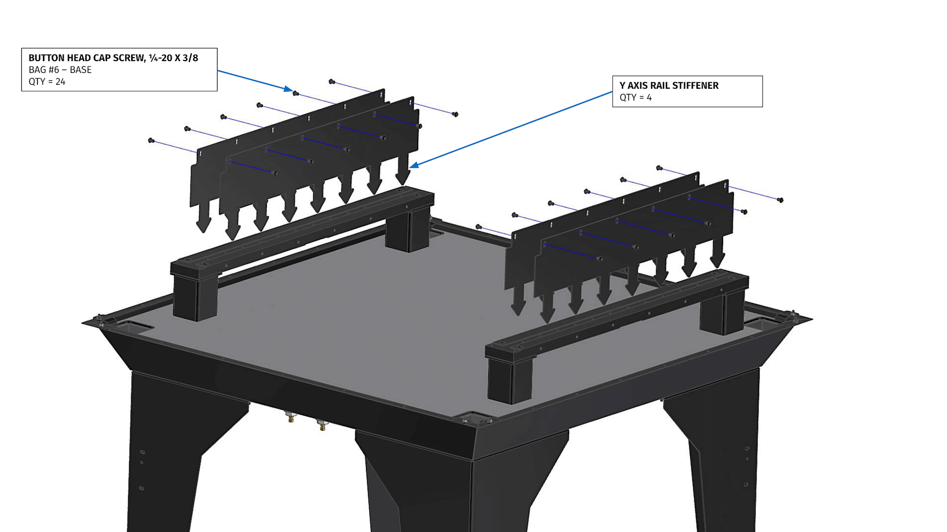
Hi Peter, Thank you for this information, but isn't it true that there will be always some part below the rails that is in the air it be directly or the machine table, after all i can't support the rails all the way to the ground, also this rails is 30mm thick i can have it 40mm even + 20mm linear way guide above it, it's not enough for the stiffness ? about distribute the spacing unevenly it's a good idea i will take it, also there will be Rail stiffeners on both side and they will be held in place at the bottom by concrete like this image Originally Posted by peteeng
By the way I'm copying a existing machine design called "MR-1 CNC Gantry Mill" just fixing it to suite the way i can manufacture it, and at the end i will do many simulation to make sure the parts have the minimum deflection required to get the accuracy i want. Originally Posted by peteeng
-
03-09-2023, 08:43 AM #26
Member
- Join Date
- Jul 2018
- Posts
- 6337
Re: Gantry 3-axis milling machine Design preparation phase
Hi Mogi - If you look at commercial mills their rails are always mounted on substantial webs. Anything unsupported can vibrate. Thickness is relative to how stiff you want the machine to be. 100mm thick ot more maybe needed to achieve the rigidity, only you can figure that out. You say you will be doing some simulations what static stiffness are you aiming at in Newtons/micrometer (N/um) ? If you use concrete use engineering grout class C non shrink. Normal portland concrete will shrink and crack... Peter
Langmuirs machine has good points and bad, all machines are full of compromises. you just have to make a lot of good decisions...and minimise poor ones. if your going to pour concrete then why not cast a gantry? Cast the side walls? Cast machine are stiff and damp.
-
03-09-2023, 04:08 PM #27
Member
- Join Date
- Feb 2023
- Posts
- 66
Re: Gantry 3-axis milling machine Design preparation phase
Hi Peter, i'm looking for 20n/um and more as much as i can ge, also please correct me if i'm mistaken, that mean if i apply 70kgf the parts should deflect not more than 0.0254, Because i'm planing to build good frame and in the future i can upgrade the motor from stepper to servo, the linear guide rails and balls crews to a better quality one to get a better result from my machine, because i'm sure the frame i'm planning to build, the previous parts will be the weak point since linear guide rails are not preloaded and so on Originally Posted by peteeng
Yes that is a great idea, I'm doing it like Langmuirs to add cheap weight to the machine, and to hold the Y rails supports in place. Originally Posted by peteeng
Casting will cost allot to me, i'm trying to build it as rigid as possible, with a fair amount of cost that i can handle...Mogi Originally Posted by peteeng
-
03-09-2023, 09:40 PM #28
Member
- Join Date
- Feb 2023
- Posts
- 66
Re: Gantry 3-axis milling machine Design preparation phase
Hi Peter, here is a simulation i tried with stiffeners and without, not sure i did it right or not Originally Posted by peteeng


If the result are how it should be, that mean this support rail hanging like that, have stiffness of about 380n/um to 800n/um depends on which design i go with, also i guess the design with stiffener will help stop the vibration more than just adding more stiffness.
-
03-09-2023, 09:42 PM #29
Member
- Join Date
- Jul 2018
- Posts
- 6337
Re: Gantry 3-axis milling machine Design preparation phase
Hi Mogi - By casting I mean casting in concrete which is cheap. From experience and other Makers its unlikely you will upgrade the machine mechanically in future. You may use the machine to build another machine and that is common and sensible. Every time you make a machine they get much better. Modifying a machine is rarely a leap forward. If you want 20N/um then you have to aim at 40 or 50N/um in the model as the models you make are perfect and do not include various things like friction at connections. 40N/um models are very big! but you will find this out when you get there. I disagree with the stance a machine has to be heavy. In Langmuirs case I'm a little baffled to why they did this. Steel is cheap weight too and adds stiffness. Steel is 200GPa and concrete is 30GPa modulus. The strain will preferential travel down the stiffest path and in the MR-1 case may bypass the base and stay in the frame (so why have the concrete?) ... Since the machine is freighted I see that it is an approach that you can add the concrete anywhere.
Think about casting in concrete and the high wall/rail design is ideal in class C grout. Since modelling is free make a simple steel frame model and a simple concrete model and see which wins. SIKA have a few suitable grouts (class C) and its E=40GPa This also allows you to cast a gantry with a step to take care of the different stack heights between the ballscrew nut and the track car, things that you will have to figure out... MDF moulds are cheap and easy to make. Peter
Most cast high wall designs make the base and the walls one piece but they can be separate pieces which are bolted together or glued (epoxy) together to keep part weight down so they can be handled easier. Your steel machine will be very heavy anyway. Concrete is 2300kg/m3 so is similar to aluminium in "weight" per volume...
Your vertical stiffeners are bonded the rail member. In reality they will be bolted? This will be inefficient say 50-75% of what you have modelled... If you can model a bolted connection that would be better.
Hi Mogi - The 20N/um is at the tool for the whole machine. Individual parts will be much stiffer. Once you get your machine modelled you can also apply a displacement at the tool and the FE will calculate the load required to move it that far. So I apply 0.001mm and see what Newtons I get. Or apply 1mm and scale... you also need to restrain the bed not the machine frame so model a small vice say so the loadpath is form tool to vice...
Also I have not yet tried self levelling concrete to finish the tops or the base. But what I see and read self levelling should be good enough, then a steel or aluminium plate can be epoxied to the top for the mechanical bits. cheers
-
03-09-2023, 10:48 PM #30
Member
- Join Date
- Jul 2018
- Posts
- 6337
Re: Gantry 3-axis milling machine Design preparation phase
Hi Mogi - a concrete casting like this attached. I have always been hesitant due to getting the "top" flat and being able to cast the bottom or sides with a honeycomb as I thought I had to cast up[side down. But by casting upright you can place the voids in the cast to get the honeycomb then at the end use self levelling to get the tops level & flat... I have cast several small things in grout and it has been easy and the results are really good. You can take your time with the moulds and make sure they are exactly as you want them then cast in your own time... I think its a great process. Peter
https://youtu.be/4lE81uPfA64
I've just made some carbon fibre panels and had them tested and they got E=40GPa. I get some concrete grout from a local supplier and get 40GPa out of the bag just add water. No vacuum or plastic consumables expensive tapes and sealing issues just pour it into the mould. I'd go grout... Heres a grout with 56Gpa modulus...sika 3350
I can tell you're a designer and by using grout you can get the geometry and thicknesses where you want plus a bit of flair and it will be sexy. Using steel will be limiting and frustrating using std sections and nuts and bolts have limits too... Keep at it...
-
03-10-2023, 12:21 AM #31
Member
- Join Date
- Jul 2018
- Posts
- 6337
Re: Gantry 3-axis milling machine Design preparation phase
Hi Mogi - Another thought. Mills throw material everywhere! Its worthwhile leaving some space at the top of the walls to create an enclosure land. The enclosure can be metal or plywood etc but if you don't think about it now you won't have real estate to use. My next router/mill will have very high walls that become the enclosure. Dust and swarf are big issues once you get into it. Plus if it has a "roof" you can feed control cables from the roof vs along the sides then across and all over the shop to get to Z...Peter
-
03-10-2023, 10:11 AM #32
Member
- Join Date
- Feb 2023
- Posts
- 66
Re: Gantry 3-axis milling machine Design preparation phase
Hi Peter, Thank you for you awesome advices for sure it will change the way I look into things, I have about 1 year to plan for the machine, then I will build it, too busy with other stuff + I got new born that is why is the delay, so I'm spending the time collecting data and designing Originally Posted by peteeng
Bout the grout, in my country the cheapest 25kg pack I can find cost about 18$ to 25$ and each of this package can cover 12.5 liter of volume
I calculated my machine bed it will be 160cm x 120cm x 10cm so only with 10cm grout as bed it will be 0.2 cubic meter which mean 200 liter so I will need 16 pack of this grout so about 300$ at minimum
In my country scrap steel 1kg cost 0.8$ and new Steel cost 1.6$ So I'm not sure which is the logical design to go with
Same volume with concret can cost at max 30$
About the sides Maybe I can support them with steel pipe that is filled with this grout pr even without, I have to check on Solidworks to play with the design to reach the goal I'm looking for.
-
03-10-2023, 10:50 AM #33
Member
- Join Date
- Feb 2023
- Posts
- 66
Re: Gantry 3-axis milling machine Design preparation phase
Hi Peter, I'm planing to have a enclosure, will design it with the machine so it can fit good with it, maybe not gonna build it in the beginning, but I will have place for connecting it and so on, also flood coolant pipes and drainage. Originally Posted by peteeng
-
03-12-2023, 07:15 AM #34
Member
- Join Date
- Jul 2018
- Posts
- 6337
Re: Gantry 3-axis milling machine Design preparation phase
Hi Mogi - I feel its a trap to make cost decisions too early. You have to make the "best" decision. Sure steel is cheap but you will encounter lots of issues designing with it. You can halve the volume of things by using in-fills/honeycombing voiding. Even add styrofoam bubbles to the mix to halve the density.. Even add air to the mix to make lightweight concrete. But its up to you... Keep researching. Peter
-
03-12-2023, 09:01 PM #35
Member
- Join Date
- Feb 2023
- Posts
- 66
Re: Gantry 3-axis milling machine Design preparation phase
Hi peter, Yes you are right i should think about performance / price, not just price, i will keep researching Thank you. Originally Posted by peteeng
-
03-12-2023, 09:31 PM #36
Member
- Join Date
- Jul 2018
- Posts
- 6337
Re: Gantry 3-axis milling machine Design preparation phase
Hi Mogi - I have made MDF & plywood machine bases that will machine plastics, timber and aluminium easily. You describe the machine as a Mill and mention Steel. These two words really impact what you are trying to do. Steel requires extreme stiffness and damping, Plus it also requires a low speed high torque spindle. The spindle is going to be a large rabbit hole for you and its worth researching this aspect before much longer as it can change how the Z axis is going to work. Your going to need space for pulleys and large motors, probably an AC servo. If you use a high speed spindle like on a router for steel you will need one with very good bearings plus you will have to adopt a light cut very high speed machining technique. There are people doing this, but its early days in this area of work. Or you remove "Mill and steel" from the spec and life becomes very much easier. But aiming at a Mill is not a bad thing, just its a very tough call for your first machine... Look up my Milli thread, years of research and still no result. Peter
-
03-13-2023, 12:09 AM #37
Member
- Join Date
- Nov 2013
- Posts
- 4372
Re: Gantry 3-axis milling machine Design preparation phase
Hi,
I second that, as soon as you start to cut steel then that is a totally different machine to anything you have discussed thus far.
Take a look at any of the many drill-mills out there, like this one as an example. Its good enough....just....to do steel. If you want to cut steel
you'll need to do at least as well if not better...and this thing is made of cast iron and has ground dovetails....not an easy task to match let
alone exceed.
https://rongfu.com/mill-drill-machin...-machine-rf45/
Craig
-
03-13-2023, 11:22 AM #38
Member
- Join Date
- Jul 2018
- Posts
- 6337
Re: Gantry 3-axis milling machine Design preparation phase
Hi Mogi - I'm starting to think about Milli again and have done some generative work in Fusion360. Does Solidworks have generative functions? Peter
-
03-13-2023, 01:38 PM #39
Member
- Join Date
- Feb 2023
- Posts
- 66
Hi Peter, is this what you mean ? Originally Posted by peteeng
https://m.youtube.com/watch?v=XcXENyRUcQA
-
03-13-2023, 04:48 PM #40
Member
- Join Date
- Jan 2023
- Posts
- 436
Re: Gantry 3-axis milling machine Design preparation phase
you can cut steel with a router, but its gonna be at a level of a dental mill, that is tiny tools, very high speeds, 20k+ rpm. Stiffness is key to any performance. If you want to cut steel with a langmuirs copy, I have very bad feelings about that. If you want to cut steel faster you need a different frame for that. If you want absolute best performance at a budget, you need a double column raising gantry.
What's your budget and what kind of accuracy do you want? Do you want to produce parts for fun? or occasionally as a jobshop? There's plenty of options. We can guide you but we need more data.
Yes, Pete, solidworks has generative design and topology optimizition. But it deals very poorly with meshes, I mean, it barely even works with them. Think things like lag, stutters and crashes if the mesh has any decent amount of polygons. Meshes are a nightmare to work with in sw.

 Reply With Quote